ELTR 120 (Semiconductors 1), section 1 Recommended schedule ...

ELTR 125 (Semiconductors 2), section 3
Recommended schedule
Day 1Topics: Basic oscillator theory and relaxation oscillator circuitsQuestions: 1 through 10Lab Exercise: BJT multivibrator circuit, astable (question 51)
Day 2Topics: Phase-shift and resonant oscillator circuitsQuestions: 11 through 20Lab Exercise: Wien bridge oscillator, BJT (question 52)
Day 3Topics: HarmonicsQuestions: 21 through 30Lab Exercise: Colpitts oscillator, BJT (question 53)
Day 4Topics: Fundamentals of radio, amplitude modulation, and frequency modulation (optional)Questions: 31 through 50Lab Exercise: Troubleshooting practice (oscillator/amplifier circuit – question 55)Just for fun (not required): AM radio transmitter (question 54)
Day 5Exam 3: includes Oscillator Circuit performance assessmentTroubleshooting Assessment due: oscillator/amplifier circuit (question 55)Question 56: Troubleshooting logQuestion 57: Sample troubleshooting assessment grading criteria
Troubleshooting practice problemsQuestions: 58 through 67
General concept practice and challenge problemsQuestions: 68 through the end of the worksheet
1

ELTR 125 (Semiconductors 2), section 3
Skill standards addressed by this course section
EIA Raising the Standard; Electronics Technician Skills for Today and Tomorrow, June 1994
C Technical Skills – AC circuitsC.02 Demonstrate an understanding of the properties of an AC signal.C.03 Demonstrate an understanding of the principles of operation and characteristics of sinusoidal and non-
sinusoidal wave forms.
E Technical Skills – Analog CircuitsE.20 Understand principles and operations of sinusoidal and non-sinusoidal oscillator circuits.E.21 Troubleshoot and repair sinusoidal and non-sinusoidal oscillator circuits.E.27 Understand principles and operations of signal modulation systems (AM, FM, stereo). Partially met –
basic AM and FM only.
B Basic and Practical Skills – Communicating on the JobB.01 Use effective written and other communication skills. Met by group discussion and completion of labwork.B.03 Employ appropriate skills for gathering and retaining information. Met by research and preparation
prior to group discussion.B.04 Interpret written, graphic, and oral instructions. Met by completion of labwork.B.06 Use language appropriate to the situation. Met by group discussion and in explaining completed labwork.B.07 Participate in meetings in a positive and constructive manner. Met by group discussion.B.08 Use job-related terminology. Met by group discussion and in explaining completed labwork.B.10 Document work projects, procedures, tests, and equipment failures. Met by project construction and/or
troubleshooting assessments.C Basic and Practical Skills – Solving Problems and Critical Thinking
C.01 Identify the problem. Met by research and preparation prior to group discussion.C.03 Identify available solutions and their impact including evaluating credibility of information, and locating
information. Met by research and preparation prior to group discussion.C.07 Organize personal workloads. Met by daily labwork, preparatory research, and project management.C.08 Participate in brainstorming sessions to generate new ideas and solve problems. Met by group discussion.
D Basic and Practical Skills – ReadingD.01 Read and apply various sources of technical information (e.g. manufacturer literature, codes, and
regulations). Met by research and preparation prior to group discussion.E Basic and Practical Skills – Proficiency in Mathematics
E.01 Determine if a solution is reasonable.E.02 Demonstrate ability to use a simple electronic calculator.E.05 Solve problems and [sic] make applications involving integers, fractions, decimals, percentages, and
ratios using order of operations.E.06 Translate written and/or verbal statements into mathematical expressions.E.09 Read scale on measurement device(s) and make interpolations where appropriate. Met by oscilloscope
usage.E.12 Interpret and use tables, charts, maps, and/or graphs.E.13 Identify patterns, note trends, and/or draw conclusions from tables, charts, maps, and/or graphs.E.15 Simplify and solve algebraic expressions and formulas.E.16 Select and use formulas appropriately.E.17 Understand and use scientific notation.
2

ELTR 125 (Semiconductors 2), section 3
Common areas of confusion for students
Difficult concept: Calculating phase shift of RC network.The only real difficulty here is the lapse in time between when most students study RC circuit analysis
and the time they study phase-shift oscillator circuits. Calculating the phase shift of a series RC circuit is assimple as drawing its impedance triangle, and then properly identifying which two sides represent the input(total) and output voltages in order to identify which angle you must calculate.
Difficult concept: Fourier analysis.No doubt about it, Fourier analysis is a strange concept to understand. Strange, but incredibly useful!
While it is relatively easy to grasp the principle that we may create a square-shaped wave (or any othersymmetrical waveshape) by mixing together the right combinations of sine waves at different frequencies andamplitudes, it is far from obvious that any periodic waveform may be decomposed into a series of sinusoidalwaves the same way. The practical upshot of this is that is it possible to consider very complex waveshapesas being nothing more than a bunch of sine waves added together. Since sine waves are easy to analyze in thecontext of electric circuits, this means we have a way of simplifying what would otherwise be a dauntinglycomplex problem: analyzing how circuits respond to non-sinusoidal waveforms.
The actual ”nuts and bolts” of Fourier analysis is highly mathematical and well beyond the scope of thiscourse. Right now all I want you to grasp is the concept and significance of equivalence between arbitrarywaveshapes and series of sine waves.
A great way to experience this equivalence is to play with a digital oscilloscope with a built-in spectrumanalyzer. By introducing different wave-shape signals to the input and switching back and forth betweenthe time-domain (scope) and frequency-domain (spectrum) displays, you may begin to see patterns that willenlighten your understanding.
3

Questions
Question 1
Define what an oscillator circuit is, using your own words. Give a few examples of oscillators at workin common devices and systems.
file 01075
Question 2
The circuit shown here is called a relaxation oscillator. It works on the principles of capacitor chargingover time (an RC circuit), and of the hysteresis of a gas-discharge bulb: the fact that the voltage requiredto initiate conduction through the bulb is significantly greater than the voltage below which the bulb ceasesto conduct current.
In this circuit, the neon bulb ionizes at a voltage of 70 volts, and stops conducting when the voltagefalls below 30 volts:
Time
VC
C
R
Graph the capacitor’s voltage over time as this circuit is energized by the DC source. Note on yourgraph at what times the neon bulb is lit:
file 00430
4

Question 3
Replace the fixed-value resistor with a potentiometer to adjust the blinking rate of the neon lamp, inthis relaxation oscillator circuit. Connect the potentiometer in such a way that clockwise rotation of theknob makes the lamp blink faster:
CW
file 00431
5

Question 4
This relaxation oscillator circuit uses a resistor-capacitor combination (R1 - C1) to establish the timedelay between output pulses:
27 Ω
1 kΩ
Output10 µF
47 kΩ
TP1
R1
C1
R2
R3
The voltage measured between TP1 and ground looks like this on the oscilloscope display:
trigger
timebase
s/divDC GND AC
X
GNDDCV/div
vertical
OSCILLOSCOPE
Y
AC
A slightly different version of this circuit adds a JFET to the capacitor’s charge current path:
27 Ω
1 kΩ
Output 10 µF
TP1
C1
R2
R3
R1
10 kΩ
Now, the voltage at TP1 looks like this:
6

trigger
timebase
s/divDC GND AC
X
GNDDCV/div
vertical
OSCILLOSCOPE
Y
AC
What function does the JFET perform in this circuit, based on your analysis of the new TP1 signalwaveform? The straight-line charging voltage pattern shown on the second oscilloscope display indicateswhat the JFET is doing in this circuit.
Hint: you don’t need to know anything about the function of the unijunction transistor (at the circuit’soutput) other than it acts as an on/off switch to periodically discharge the capacitor when the TP1 voltagereaches a certain threshold level.
Challenge question: write a formula predicting the slope of the ramping voltage waveform measured atTP1.
file 01186
Question 5
This circuit shown here is for a timing light: a device that uses a pulsed strobe lamp to ”freeze” themotion of a rotating object.
Flashtube
Q1
Q2 Q3 Q4
R1R2
C1
R3
R4 R5 R6
C2T1
Which component(s) in this circuit form the oscillator section? What type of oscillator is used in thiscircuit? Which component values have a direct influence on the frequency of the flash tube’s output?
file 01078
7

Question 6
Explain the principle of operation in this astable multivibrator circuit:
R1 C1
R2 R3
C2R4
Q1 Q2
Also, identify where you would connect to this circuit to obtain an output signal. What type of signalwould it be (sine wave, square wave, ramp or triangle wave, etc.)?
file 01079
Question 7
This astable multivibrator circuit will oscillate with a 50% duty cycle if the components aresymmetrically sized:
R1 C1
R2 R3
C2R4
Q1 Q2
-V
Component values for50% duty cycle:
R2 = R3
R1 = R4
C1 = C2
Q1 ≡ Q2
Determine which component(s) would have to be re-sized to produce a duty cycle other than 50%.file 02254
Question 8
If you have ever used a public address (”PA”) amplifier, where sounds detected by a microphone areamplified and reproduced by speakers, you know how these systems can create ”screeching” or ”howling”sounds if the microphone is held too close to one of the speakers.
The noise created by a system like this is an example of oscillation: where the amplifier circuitspontaneously outputs an AC voltage, with no external source of AC signal to ”drive” it. Explain whatnecessary condition(s) allow an amplifier to act as an oscillator, using a ”howling” PA system as the example.In other words, what exactly is going on in this scenario, that makes an amplifier generate its own AC outputsignal?
file 01074
8

Question 9
How many degrees of phase shift must the feedback circuit (the box in this schematic) introduce to thesignal in order for this common-emitter amplifier circuit to oscillate?
+V
R1
R2
Feedbacknetwork
C1
RC
RE CE
We know that oscillator circuits require ”regenerative” feedback in order to continuously sustainoscillation. Explain how the correct amount of phase shift is always provided in the feedback circuit toensure that the nature of the feedback is always regenerative, not degenerative. In other words, explain whyit is not possible to incorrectly choose feedback network component values and thus fail to achieve the properamount of phase shift.
file 01080
9

Question 10
How many degrees of phase shift must the feedback circuit (the box in this schematic) introduce to thesignal in order for this two-stage common-emitter amplifier circuit to oscillate?
+V
Feedbacknetwork
Why is this amount of phase shift different from that of a single-transistor oscillator?file 01212
Question 11
Explain what the Barkhausen criterion is for an oscillator circuit. How will the oscillator circuit’sperformance be affected if the Barkhausen criterion falls below 1, or goes much above 1?
file 01211
10

Question 12
One way to achieve the phase shift necessary for regenerative feedback in an oscillator circuit is to usemultiple RC phase-shifting networks:
C2
VoutC1 C3 C4
C5
R1 R2 R3
R4
R5
R6
R7
Q1
VCC
What must the voltage gain be for the common-emitter amplifier if the total voltage attenuation for thethree phase-shifting RC networks is -29.25 dB?
file 02263
11

Question 13
RC phase-shift oscillator circuits may be constructed with different numbers of RC sections. Shownhere are schematic diagrams for three- and four-section RC oscillators:
Vout
VCC
C
R
C
R
C
R
Vout
VCC
C
R
C
R
C
R
C
R
What difference will the number of sections in the oscillator circuit make? Be as specific as you can inyour answer.
file 02264
12

Question 14
Calculate the output voltages of this Wien bridge circuit, if the input voltage is 10 volts RMS at afrequency of 159.155 Hz:
1 µF
1 µF
1 kΩ
1 kΩ
Vin10 VAC
159.155 Hz
1 kΩ
1 kΩ
Vout1
Vout2RMS
file 01213
Question 15
In this Wien bridge circuit (with equal-value components all around), both output voltages will havethe same phase angle only at one frequency:
Vout1
Vout2
R
RR
R
C
CVin
At this same frequency, Vout2 will be exactly one-third the amplitude of Vin. Write an equation in termsof R and C to solve for this frequency.
file 02262
13

Question 16
The circuit shown here is a Wien-bridge oscillator:
+V
0.22 µF
4.7 kΩ
4.7 kΩ
0.22 µF
3.9 kΩ
3.9 kΩ
If one side of the Wien bridge is made from a potentiometer instead of two fixed-value resistors, thisadjustment will affect both the amplitude and the distortion of the oscillator’s output signal:
+V
Amplitude/distortion
adjustment
0.22 µF
4.7 kΩ
4.7 kΩ
0.22 µF
Explain why this adjustment has the effect that it does. What, exactly, does moving the potentiometerdo to the circuit to alter the output signal? Also, calculate the operating frequency of this oscillator circuit,and explain how you would make that frequency adjustable as well.
14

file 01215
Question 17
Identify the type of oscillator circuit shown in this schematic diagram, and explain the purpose of thetank circuit (L1 and C1):
+V
R1
R2
C1
L1
C2
RC
RE CE
Also, write the equation describing the operating frequency of this type of oscillator circuit.file 01082
Question 18
Identify the type of oscillator circuit shown in this schematic diagram, and explain the purpose of thetank circuit (L1, C1, and C2):
+V
R1
R2
C1
L1
C2
C3
RC
RE CE
Also, write the equation describing the operating frequency of this type of oscillator circuit.file 01081
15

Question 19
Describe the purpose and operation of a crystal in an oscillator circuit. What physical principle doesthe crystal exploit, and what other components could be substituted in place of a crystal in an oscillatorcircuit?
file 01077
Question 20
Identify the type of oscillator circuit shown in this schematic diagram, and explain the purpose of thecrystal:
+V
R1
R2
C1 C2
C3
XtalRC
RE CE
Challenge question: this type of oscillator circuit is usually limited to lower power outputs than eitherHartley or Colpitts designs. Explain why.
file 01083
Question 21
What is a harmonic frequency? If an oscillator circuit outputs a fundamental frequency of 12 kHz,calculate the frequencies of the following harmonics:
• 1st harmonic =• 2nd harmonic =• 3rd harmonic =• 4th harmonic =• 5th harmonic =• 6th harmonic =
file 02255
16

Question 22
An interesting thing happens if we take the odd-numbered harmonics of a given frequency and add themtogether at certain diminishing ratios of the fundamental’s amplitude. For instance, consider the followingharmonic series:
(1 volt at 100 Hz) + (1/3 volt at 300 Hz) + (1/5 volt at 500 Hz) + (1/7 volt at 700 Hz) + . . .1st harmoni 1st + 3rd1st + 3rd + 5th 1st + 3rd + 5th + 7th
Here is what the composite wave would look like if we added all odd-numbered harmonics up to the13th together, following the same pattern of diminishing amplitudes:1st + 3rd + 5th + 7th + 9th + 11th + 13th
If we take this progression even further, you can see that the sum of these harmonics begins to appearmore like a square wave:
17

All odd-numbered harmoni s up to the 35th
This mathematical equivalence between a square wave and the weighted sum of all odd-numberedharmonics is very useful in analyzing AC circuits where square-wave signals are present. From the perspectiveof AC circuit analysis based on sinusoidal waveforms, how would you describe the way an AC circuit ”views”a square wave?
file 01597
Question 23
In the early 1800’s, French mathematician Jean Fourier discovered an important principle of waves thatallows us to more easily analyze non-sinusoidal signals in AC circuits. Describe the principle of the Fourierseries, in your own words.
file 00650
Question 24
Identify the type of electronic instrument that displays the relative amplitudes of a range of signalfrequencies on a graph, with amplitude on the vertical axis and frequency on the horizontal.
file 00649
18

Question 25
Suppose an amplifier circuit is connected to a sine-wave signal generator, and a spectrum analyzer usedto measure both the input and the output signals of the amplifier:
0 dB
-20 dB
-40 dB
-60 dB
-80 dB
-100 dB
-120 dB
1 2 3 4 5 6 7 8 9 10
0 dB
-20 dB
-40 dB
-60 dB
-80 dB
-100 dB
-120 dB
1 2 3 4 5 6 7 8 9 10
Amplifier
Input Output
Power
1 kHz
Interpret the two graphical displays and explain why the output signal has more ”peaks” than the input.What is this difference telling us about the amplifier’s performance?
file 03307
Question 26
What causes harmonics to form in the output of a transistor amplifier circuit, if the input waveform isperfectly sinusoidal (free from harmonics)? Be as specific as you can in your answer.
file 03746
Question 27
What causes harmonics to form in the output of a transistor oscillator circuit such as a Colpitts or aHartley, which is designed to produce a sinusoidal signal? Be as specific as you can in your answer.
file 03747
Question 28
A clever way to produce sine waves is to pass the output of a square-wave oscillator through a low-passfilter circuit:
Square-waveoscillator LP filter
Explain how this principle works, based on your knowledge of Fourier’s theorem.file 03754
19

Question 29
What causes harmonics to form in AC electric power systems?file 00653
Question 30
Explain how the following power-line harmonic analyzer circuit works:
AC input(60 Hz fundamental)
V
L1 C1
L2 C2
L3 C3
L4 C4
L5 C5
R1
R2
R3
R4
R5
1 kΩ
1 kΩ
1 kΩ
1 kΩ
1 kΩ
1st
2nd3rd
4th
5th
Harmonic # L# value C# value1st 20 to 22 H 0.33 µF2nd 11 to 12 H 0.15 µF3rd 5 to 6 H 0.15 µF4th 1.5 to 2.5 H 0.22 µF5th 1 to 1.5 H 0.27 µF
file 03694
20

Question 31
What does the acronym RF stand form, in reference to radio-related electronics?file 03459
Question 32
We know at this point that any circuit comprised of inductance (L) and capacitance (C) is capableof resonating: attaining large values of AC voltage and current if ”excited” at the proper frequency. Theso-called tank circuit is the simplest example of this:
C L
Tank circuit
The less resistance (R) such a circuit has, the better its ability to resonate.
We also know that any piece of wire contains both inductance and capacitance, distributed along itslength. These properties are not necessarily intentional – they exist whether we would want them to or not:
Wire
Given that the electrical resistance of a continuous piece of metal wire is usually quite low, describewhat these natural properties of inductance and capacitance mean with regard to that wire’s function as anelectrical element.
file 03461
21
Question 33
Shown here is a simple quarter-wave antenna, comprised of a single wire projecting vertically from oneterminal of an RF voltage source, the other terminal connected to earth ground:
Wire
RF source
Re-draw this illustration, showing the equivalent inductance and capacitance exhibited by this antenna.Show these properties using actual inductor and capacitor symbols.
file 03460
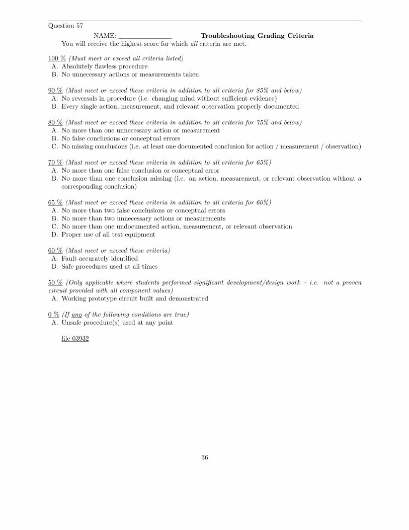
Question 34
Shown here is a simple dipole antenna, comprised of two equal-length wires projecting from the terminalsof an RF voltage source:
Wire Wire
RF source
Re-draw this illustration, showing the equivalent inductance and capacitance exhibited by this antenna.Show these properties using actual inductor and capacitor symbols.
file 03458
Question 35
A Scottish physicist named James Clerk Maxwell made an astonishing theoretical prediction in thenineteenth century, which he expressed with these two equations:
∮
E · dl = −dΦB
dt
∮
B · dl = µ0I + µ0ǫ0dΦE
dt
The first equation states that an electric field (E) will be produced in open space by a changing magneticflux
(
dΦB
dt
)
. The second equation states than a magnetic field (B) will be produced in open space either by
an electric current (I) or by a changing electric flux(
dΦE
dt
)
. Given this complementary relationship, Maxwellreasoned, it was possible for a changing electric field to create a changing magnetic field which would thencreate another changing electric field, and so on. This cause-and-effect cycle could continue, ad infinitum,with fast-changing electric and magnetic fields radiating off into open space without needing wires to carryor guide them. In other words, the complementary fields would be self-sustaining as they traveled.
Explain the significance of Maxwell’s prediction, especially as it relates to electronics.file 03462
22

Question 36
In 1887, a German physicist named Heinrich Hertz successfully demonstrated the existence ofelectromagnetic waves. Examine the following schematic of the apparatus he used to do this, and explainwhat significance Hertz’s discovery has to do with your study of electronics:
Spark gap
Metal plate
Metal plate
Smallspark gap
Wire loopA few meters’
distance
file 02278
Question 37
Given James Clerk Maxwell’s prediction of electromagnetic waves arising from the self-sustenance ofchanging electric and magnetic fields in open space, what sort of a device or collection of devices do you thinkwe would need to create electromagnetic waves oscillating at a frequency within the range attainable by anelectric circuit? In other words, what kind of component(s) would we attach to a source of high-frequencyAC to radiate these waves?
file 03463
Question 38
Although radio transmitter antennae ideally possesses only inductance and capacitance (no resistance),in practice they are found to be very dissipative. In other words, they tend to act as large resistors to thetransmitters they are connected to. Explain why this is. In what form is the dissipated energy manifest(heat, light, or something else)?
file 02280
Question 39
A crystal goblet may be shattered if exposed to high-intensity sound. Less volume is required to shatterthe goblet if the sound is at such a frequency that it resonates with the goblet’s natural frequency. That is,there will be maximum transfer of energy to the goblet if the sound waves are transmitted at precisely thegoblet’s resonant frequency.
How does this phenomenon relate to the reception of radio waves, since we know that a radio antennaeffectively acts as a resonant LC (inductance/capacitance) network?
file 02282
23

Question 40
Radio waves are comprised of oscillating electric and magnetic fields, which radiate away from sourcesof high-frequency AC at (nearly) the speed of light. An important measure of a radio wave is its wavelength,defined as the distance the wave travels in one complete cycle.
Suppose a radio transmitter operates at a fixed frequency of 950 kHz. Calculate the approximatewavelength (λ) of the radio waves emanating from the transmitter tower, in the metric distance unit ofmeters. Also, write the equation you used to solve for λ.
file 01819
Question 41
A very important concept in electronics is modulation. Explain what ”modulation” means, and give oneor two examples of it.
file 02266
Question 42
A primitive form of communication long ago was the use of smoke signals: interrupting the rising streamof smoke from a fire by waving a blanket over it so that specific sequences of smoke ”puffs” could be seensome distance away. Explain how this is an example of modulation, albeit in a non-electronic form.
file 02265
24

Question 43
One of the simplest electronic methods of modulation is amplitude modulation, or AM. Explain how ahigh-frequency carrier signal would be modulated by a lower-frequency signal such as in the case of the twosignals shown here in the time domain:Carrier signal
Time
Modulating signal
TimeModulated signal
Timefile 02273
25

Question 44
A circuit often used to amplitude-modulate a carrier signal is a multiplier:
Modulating signal
Carrier signal x
y
x ⋅ y
Multiplier
Explain how the instantaneous multiplication of two sine waves results in amplitude modulation. Ifpossible, graph this on a graphing calculator or other computer plotting device.
file 02284
26

Question 45
A common modulation technique employed in radio broadcasting is frequency modulation, or FM.Explain how a high-frequency carrier signal would be modulated by a lower-frequency signal such as inthe case of the two signals shown here in the time domain:Carrier signal
Time
Modulating signal
TimeModulated signal
Timefile 02274
27

Question 46
At the heart of an FM transmitter is a circuit called a voltage-controlled oscillator, or VCO. Explainwhat the purpose of a VCO is, and how this directly relates to frequency modulation.
file 02276
Question 47
This is a schematic for a very simple VCO:
RFC
+V
RF output
Frequency-modulated
RFC
+V
Audiofrequency
input
The oscillator is of the ”Colpitts” design. The key to understanding this circuit’s operation is knowinghow the varactor diode responds to different amounts of DC bias voltage. Explain how this circuit works,especially how the diode exerts control over the oscillation frequency. Why does the output frequency varyas the control voltage varies? Does the output frequency increase or decrease as the control voltage inputreceives a more positive voltage?
Note: ”RFC” is an acronym standing for Radio-Frequency Choke, an iron-core inductor whose purposeit is to block radio frequency current from passing through.
file 02283
28

Question 48
This is a schematic for a simple VCO:
+V
Vout
+VVcontrol
The oscillator is of the RC ”phase shift” design. Explain how this circuit works. Why does the outputfrequency vary as the control voltage varies? Does the output frequency increase or decrease as the controlvoltage input receives a more positive voltage?
Hint: the JFETs in this circuit are not functioning as amplifiers!file 01187
Question 49
FM tends to be a far more noise-resistant means of signal modulation than AM. For instance, the”crackling” form of radio interference caused by natural lightning or the ”buzzing” noise produced by high-voltage power lines are both easy to hear on an AM radio, but absent on an FM radio. Explain why.
file 02275
Question 50
When transmitting audio information (such as music and speech) in the form of radio waves, why bothermodulating a high-frequency carrier signal? Why not just connect a powerful audio amplifier straight to anantenna and broadcast the audio frequencies directly?
file 02277
29

Question 51
Given conditions
Version:
Schematic
ParametersPredicted Measured
R1
R2
Q1 Q2
C1 C2
R1 = R2 = C1 =
C2 =
R3R4
R4 = R3 =
Duty Cycle(at Q1 collector)
Potentiometer turnedfully clockwise
VCC
VCC =
Fault analysis
Suppose component fails open
shorted
other
What will happen in the circuit?
Competency: BJT multivibrator circuit, astable
file 01939
30

Question 52
Given conditions
Version:
Schematic
Parameters
Predicted Measured
C2
R4 =
Vout
C1
C3
C4
R4
R5
R6
R7
R5 =
R6 = R7 =
fout
Competency: Wien bridge oscillator, BJT
Q1 Q2
R1R3
C1 = C2 = C3 = C4 =
R3 =
R2
R1 = R2 =
VCC
VCC =
Rpot
Rpot =
Fault analysis
Suppose component fails open
shorted
other
What will happen in the circuit?
file 01975
31

Question 53
Given conditions
Version:
Schematic
Parameters
Predicted Measured
Vout
Q1
fout
Competency: Colpitts oscillator, BJT
R1
R2C3
L1
C1
C2
C1 = C2 = C3 =L1 =
R1 = R2 =
VCC
VCC =
Fault analysis
Suppose component fails open
shorted
other
What will happen in the circuit?
file 01952
32

Question 54
Given conditions
Version:
Schematic
Parameters
Predicted Measured
+V
+V =
Q1
fout
R1
R2C3
L1
C1
C2
C1 = C2 = L1 =
R1 = R2 =
R3 C4
Vsignal
Competency: AM radio transmitter
R3 =
Q2
Vsignal =
fsignal =
Antenna
Oscilloscope display of modulation
Audio signal can beheard on AM radio
C5
R4
C3 = C4 = C5 =
R4 =
file 01953
33
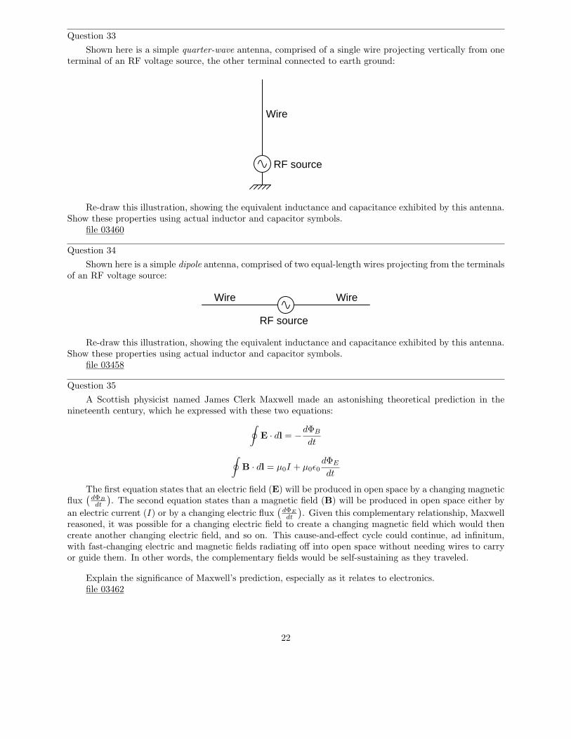
Question 55
Given conditions
Version:
Schematic
Parameters Predicted Measured
R1
R2
Q1 Q2
C1 C2
R1 =
R2 =C1 =
C2 =
R3R4
R4 =
R3 =
-V
-V =
R5 R6
C3 C4
-V
R7
-V
-V
Vout
C5
C6 R8
R9
R5 =
R6 =
R7 =
R8 =
R9 =C3 =
C4 =
C5 =
C6 =
C7
C7 =
Q3Q4
Competency: Oscillator/waveshaper/amplifier circuit
waveshape waveshape
VC(Q2)
Predicted Measuredwaveshape waveshape
Vout
VB(Q2)
VC3
VC4
VR7
Rpot
Rpot =
file 02507
34

Question 56
Conclusions(i.e. What this tells me . . . )
Troubleshooting log
(i.e. What I did and/or noticed . . . )Actions / Measurements / Observations
file 03933
35
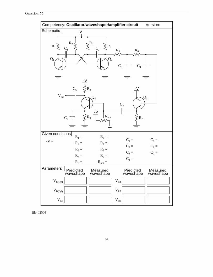
Question 57
NAME: Troubleshooting Grading CriteriaYou will receive the highest score for which all criteria are met.
100 % (Must meet or exceed all criteria listed)A. Absolutely flawless procedureB. No unnecessary actions or measurements taken
90 % (Must meet or exceed these criteria in addition to all criteria for 85% and below)A. No reversals in procedure (i.e. changing mind without sufficient evidence)B. Every single action, measurement, and relevant observation properly documented
80 % (Must meet or exceed these criteria in addition to all criteria for 75% and below)A. No more than one unnecessary action or measurementB. No false conclusions or conceptual errorsC. No missing conclusions (i.e. at least one documented conclusion for action / measurement / observation)
70 % (Must meet or exceed these criteria in addition to all criteria for 65%)A. No more than one false conclusion or conceptual errorB. No more than one conclusion missing (i.e. an action, measurement, or relevant observation without a
corresponding conclusion)
65 % (Must meet or exceed these criteria in addition to all criteria for 60%)A. No more than two false conclusions or conceptual errorsB. No more than two unnecessary actions or measurementsC. No more than one undocumented action, measurement, or relevant observationD. Proper use of all test equipment
60 % (Must meet or exceed these criteria)A. Fault accurately identifiedB. Safe procedures used at all times
50 % (Only applicable where students performed significant development/design work – i.e. not a provencircuit provided with all component values)A. Working prototype circuit built and demonstrated
0 % (If any of the following conditions are true)A. Unsafe procedure(s) used at any point
file 03932
36

Question 58
Predict how the operation of this relaxation oscillator circuit will be affected as a result of the followingfaults. Consider each fault independently (i.e. one at a time, no multiple faults):
C
R
• Capacitor C1 fails open:
• Capacitor C1 fails shorted:
• Resistor R1 fails open:
• Solder bridge (short) past resistor R1:
For each of these conditions, explain why the resulting effects will occur.file 03749
37

Question 59
Predict how the operation of this strobe light circuit will be affected as a result of the following faults.Consider each fault independently (i.e. one at a time, no multiple faults):
Flashtube
Q1
Q2 Q3 Q4
R1R2
C1
R3
R4 R5 R6
C2T1
• Capacitor C1 fails open:
• Capacitor C1 fails shorted:
• Resistor R2 fails open:
• Solder bridge (short) past resistor R2:
• Resistor R4 fails open:
• Transistor Q4 fails open (collector-to-emitter):
• Capacitor C2 fails open:
• Capacitor C2 fails shorted:
For each of these conditions, explain why the resulting effects will occur.file 03750
38

Question 60
Predict how the operation of this sawtooth-wave oscillator circuit will be affected as a result of thefollowing faults. Consider each fault independently (i.e. one at a time, no multiple faults):
OutputC1
R2
R3
R1
Q1
Q2
+V
• Capacitor C1 fails shorted:
• Resistor R1 fails open:
• JFET fails shorted (drain-to-source):
• Resistor R3 fails open:
For each of these conditions, explain why the resulting effects will occur.file 03756
39

Question 61
Predict how the operation of this astable multivibrator circuit will be affected as a result of the followingfaults. Specifically, identify the final states of the transistors (on or off) resulting from each fault. Considereach fault independently (i.e. one at a time, no multiple faults):
R1 C1
R2 R3
C2R4
Q1 Q2
• Capacitor C1 fails open:
• Capacitor C2 fails open:
• Resistor R1 fails open:
• Resistor R2 fails open:
• Resistor R3 fails open:
• Resistor R4 fails open:
For each of these conditions, explain why the resulting effects will occur.file 03751
40

Question 62
Predict how the operation of this astable multivibrator circuit will be affected as a result of the followingfaults. Specifically, identify the signals found at test points TP1, TP2, TP3, and Vout resulting from eachfault. Consider each fault independently (i.e. one at a time, no multiple faults):
R1
R2
Q1 Q2
C1 C2
R3 R4
R5 R6
C3 C4
R7
-V
Vout
C5
C6 R8
R9C7
Q3Q4
Rpot
+12 V
+12 V
TP1
TP2
TP3
+12 V
• Resistor R4 fails open:
• Resistor R5 fails open:
• Resistor R7 fails open:
• Resistor R9 fails open:
• Capacitor C7 fails shorted:
• Capacitor C4 fails shorted:
• Capacitor C5 fails open:
• Transistor Q3 fails open (collector-to-emitter):
For each of these conditions, explain why the resulting effects will occur.file 03753
41

Question 63
Identify some realistic component failures that would definitely prevent this oscillator circuit fromoscillating:
C2
VoutC1 C3 C4
C5
R1 R2 R3
R4
R5
R6
R7
Q1
-VCC
For each of the faults you propose, explain why the oscillations will cease.file 03755
Question 64
Suppose some of the turns of wire (but not all) in the primary winding of the transformer were to failshorted in this Armstrong oscillator circuit:
+V
R1
R2
C2RC
RE CE
C1
C3
T1
pri. sec.
How would this effective decreasing of the primary winding turns affect the operation of this circuit?What if it were the secondary winding of the transformer to suffer this fault instead of the primary?
file 03757
42

Question 65
Predict how the output frequency of this voltage-controlled oscillator (VCO) circuit will be affected asa result of the following faults. Consider each fault independently (i.e. one at a time, no multiple faults):
+V
+V
Frequencyadjust
R1
R2
C1
R3 C2
Q1D1
C3
C4
L1
L2
L3
C5Variablefrequency
output
• Capacitor C1 fails open:
• Inductor L1 fails open:
• Resistor R1 fails open:
• Resistor R2 fails open:
• Inductor L2 fails partially shorted:
For each of these conditions, explain why the resulting effects will occur. Note: the voltage-dependentcapacitance of a varactor diode is given by the following equation:
Cj =Co
√2V + 1
Where,CJ = Junction capacitanceCo = Junction capacitance with no applied voltageV = Applied reverse junction voltage
file 03758
43

Question 66
A technician is given a transistor testing circuit to repair. This simple circuit is an audio-frequencyoscillator, and has the following schematic diagram:
E C
B
socketTransistor
On/off
After repairing a broken solder joint, the technician notices that the DPDT switch has lost its label.The purpose of this switch is to allow polarity to be reversed so as to test both PNP and NPN transistortypes. However, the label showing which direction is for NPN and which direction is for PNP has fallen off.And, to make matters worse, the schematic diagram does not indicate which position is which.
Determine what the proper DPDT switch label should be for this transistor tester, and explain how youknow it is correct. Note: you do not even have to understand how the oscillator circuit works to be able todetermine the proper switch label. All you need to know is the proper voltage polarities for NPN and PNPtransistor types.
file 01528
44

Question 67
This electric fence-charging circuit, which is designed to produce short, high-voltage pulses on its output,has failed. Now, it produces no output voltage at all:
On/Off
To fencewire
Earth ground
Indicatorlamp
A technician does some troubleshooting and determines that the transistor is defective. She replacesthe transistor, and the circuit begins to work again, its rhythmic output pulses indicated by the neon lamp.
But after producing only a few pulses, the circuit stops working. Puzzled, the technician troubleshootsit again and finds that the transistor has failed (again). Both the original and the replacement transistorwere of the correct part number for this circuit, so the failure is not due to an incorrect component beingused. Something is causing the transistor to fail prematurely. What do you suppose it is?
file 01189
Question 68
Write an equation that solves for the impedance of this series circuit. The equation need not solve forthe phase angle between voltage and current, but merely provide a scalar figure for impedance (in ohms):
Ztotal = ???
R
X
file 01844
45

Question 69
Draw a phasor diagram showing the trigonometric relationship between resistance, reactance, andimpedance in this series circuit:
5 V RMS350 Hz
2.2 kΩ
R
C
0.22 µF
Show mathematically how the resistance and reactance combine in series to produce a total impedance(scalar quantities, all). Then, show how to analyze this same circuit using complex numbers: regarding eachof the component as having its own impedance, demonstrating mathematically how these impedances addup to comprise the total impedance (in both polar and rectangular forms).
file 01828
Question 70
Solve for all voltages and currents in this series RC circuit, and also calculate the phase angle of thetotal impedance:
48 V peak30 Hz
3k3
220n
file 01849
46

Question 71
A student is asked to calculate the phase shift for the following circuit’s output voltage, relative to thephase of the source voltage:
C
R
Vsource
Vout
He recognizes this as a series circuit, and therefore realizes that a right triangle would be appropriatefor representing component impedances and component voltage drops (because both impedance and voltageare quantities that add in series, and the triangle represents phasor addition):
R , VR
XC , VCZ
total , Vtotal
θ
Φ
The problem now is, which angle does the student solve for in order to find the phase shift of Vout? Thetriangle contains two angles besides the 90o angle, Θ and Φ. Which one represents the output phase shift,and more importantly, why?
file 03748
Question 72
Calculate the output voltage of this phase-shifting circuit, expressing it in polar form (magnitude andphase angle relative to the source voltage):
0.47 µF
Vout
Vin
10 VAC250 Hz
1.5 kΩ
file 02620
47

Question 73
Calculate the output voltage of this phase-shifting circuit, expressing it in polar form (magnitude andphase angle relative to the source voltage):
Vout
Vin
1.2 kHz
2.2 kΩ
0.033 µF
5.4 VAC
file 02621
Question 74
In this circuit, a series resistor-capacitor network creates a phase-shifted voltage for the ”gate” terminalof a power-control device known as a TRIAC. All portions of the circuit except for the RC network are”shaded” for de-emphasis:
ACsource
Lamp330 kΩ
0.068 µFTRIAC
DIAC
Calculate how many degrees of phase shift the capacitor’s voltage is, compared to the total voltageacross the series RC network, assuming a frequency of 60 Hz, and a 50% potentiometer setting.
file 00637
Question 75
Determine the input frequency necessary to give the output voltage a phase shift of 70o:
VoutVin
f = ???
0.022 µF
3.3 kΩ
file 02623
48

Question 76
Determine the input frequency necessary to give the output voltage a phase shift of 40o:
VoutVin
0.01 µF
2.9 kΩf = ???
file 02622
Question 77
Determine the input frequency necessary to give the output voltage a phase shift of -38o:
VoutVin
f = ???
8.1 kΩ
33 nF
file 02626
Question 78
Determine the input frequency necessary to give the output voltage a phase shift of -25o:
VoutVin
f = ??? 0.047 µF
1.7 kΩ
file 02625
Question 79
Spring- and weight-driven clock mechanisms always use a pendulum as an integral part of their workings.What function does a pendulum serve in a clock? What would a mechanical clock mechanism do if thependulum were removed?
Describe what the electrical equivalent of a mechanical pendulum is, and what purpose it might servein an oscillator circuit.
file 01076
49

Question 80
Two technicians are arguing over the function of a component in this oscillator circuit. Capacitor C1
has failed, and they are debating over the proper value of its replacement.
Antenna
Code key
C1
C2
C3
L1
X1
R1
Q1
One technician argues that the value of capacitor C1 helps set the oscillation frequency of the circuit,and that the value of the replacement capacitor therefore must be precisely matched to the value of theoriginal. The other technician thinks its value is not critical at all, arguing that all it does is help to providea stable DC power supply voltage. What do you think?
Also, describe the purpose of this circuit: what is it?file 01486
Question 81
How many degrees of phase shift must the feedback circuit (the square box in this schematic) introduceto the signal in order for this inverting amplifier circuit to oscillate?
Feedbacknetwork
Power source
Invertingamplifier
file 02669
50

Question 82
How many degrees of phase shift must the feedback circuit (the square box in this schematic) introduceto the signal in order for this noninverting amplifier circuit to oscillate?
Feedbacknetwork
Power source
amplifierNoninverting
file 02670
Question 83
Identify the type of oscillator circuit shown in this schematic diagram, and explain the purpose of thetank circuit (L1 and C1):
+V
R1
R2
C1
L1C2
RC
RE CE
L2 L3
Also, write the equation describing the operating frequency of this type of oscillator circuit.file 02632
51

Question 84
Identify the type of oscillator circuit shown in this schematic diagram:
+V
R1
R2
C1
L1
C2
C3
RC
RE CE
C4
Also, write the equation describing the operating frequency of this type of oscillator circuit.file 02634
Question 85
Identify the type of oscillator circuit shown in this schematic diagram, and draw the transformer phasingdots in the right places to ensure regenerative feedback:
+V
R1
R2
C2RC
RE CE
C1
C3 L1 L2
Also, write the equation describing the operating frequency of this type of oscillator circuit.file 02633
52

Question 86
Modify the schematic diagram for a Hartley oscillator to include a crystal. What advantage(s) does acrystal-controlled Hartley oscillator exhibit over a regular Hartley oscillator?
file 01084
Question 87
How does the quality factor (Q) of a typical quartz crystal compare to that of a regular LC tank circuit,and what does this indicate about the frequency stability of crystal-controlled oscillators?
file 02635
Question 88
Under certain conditions (especially with certain types of loads) it is possible for a simple one-transistorvoltage amplifier circuit to oscillate:
-V
+V
Load
Vinput
Rinput Lstray
RC
RE
Explain how this is possible. What parasitic effects could possibly turn an amplifier into an oscillator?file 01085
53

Question 89
Calculate the operating frequency of this oscillator circuit:
1 µF
1 µF
1 kΩ
1 kΩ
1 kΩ
1 kΩ
+V
Explain why the operating frequency will not be the same if the transistor receives its feedback signalfrom the other side of the bridge, like this:
1 µF
1 µF
1 kΩ
1 kΩ
1 kΩ
1 kΩ
+V
file 01214
54

Question 90
This circuit generates quasi-sine waves at its output. It does so by first generating square waves,integrating those square waves (twice) with respect to time, then amplifying the double-integrated signal:
R1
R2
Q1 Q2
C1 C2
R3R4
-V
R5 R6
C3 C4
-V
R7
-V
-V
Vout
C5
C6 R8
R9C7
Q3Q4
Rpot
Identify the sections of this circuit performing the following functions:
• Square wave oscillator:• First integrator stage:• Second integrator stage:• Buffer stage (current amplification):• Final gain stage (voltage amplification):
file 03752
Question 91
What is a harmonic frequency? If a particular electronic system (such as an AC power system) has afundamental frequency of 60 Hz, calculate the frequencies of the following harmonics:
• 1st harmonic =• 2nd harmonic =• 3rd harmonic =• 4th harmonic =• 5th harmonic =• 6th harmonic =
file 01890
55

Question 92
An octave is a type of harmonic frequency. Suppose an electronic circuit operates at a fundamentalfrequency of 1 kHz. Calculate the frequencies of the following octaves:
• 1 octave greater than the fundamental =• 2 octaves greater than the fundamental =• 3 octaves greater than the fundamental =• 4 octaves greater than the fundamental =• 5 octaves greater than the fundamental =• 6 octaves greater than the fundamental =
file 01891
Question 93
The Fourier series for a square wave is as follows:
vsquare =4
πVm
(
sin ωt +1
3sin 3ωt +
1
5sin 5ωt +
1
7sin 7ωt + · · · +
1
nsin nωt
)
Where,Vm = Peak amplitude of square waveω = Angular velocity of square wave (equal to 2πf , where f is the fundamental frequency)n = An odd integer
Electrically, we might represent a square-wave voltage source as a circle with a square-wave symbolinside, like this:
vsquare
Knowing the Fourier series of this voltage, however, allows us to represent the same voltage source as a setof series-connected voltage sources, each with its own (sinusoidal) frequency. Draw the equivalent schematicfor a 10 volt (peak), 200 Hz square-wave source in this manner showing only the first four harmonics, labelingeach sinusoidal voltage source with its own RMS voltage value and frequency:
Hint: ω = 2πf
file 02260
56

Question 94
Suppose a non-sinusoidal voltage source is represented by the following Fourier series:
v(t) = 23.2 + 30 sin(377t) + 15.5 sin(1131t + 90) + 2.7 sin(1508t − 40)
Electrically, we might represent this non-sinusoidal voltage source as a circle, like this:
v(t)
Knowing the Fourier series of this voltage, however, allows us to represent the same voltage sourceas a set of series-connected voltage sources, each with its own (sinusoidal) frequency. Draw the equivalentschematic in this manner, labeling each voltage source with its RMS voltage value, frequency (in Hz), andphase angle:
Hint: ω = 2πf
file 02259
Question 95
Calculate the power dissipated by a 25 Ω resistor, when powered by a square-wave with a symmetricalamplitude of 100 volts and a frequency of 2 kHz:
25 Ω
+100 V
-100 V
file 00651
57

Question 96
Calculate the power dissipated by a 25 Ω resistor, when powered by a square-wave with a symmetricalamplitude of 100 volts and a frequency of 2 kHz, through a 0.22 µF capacitor:
25 Ω
+100 V
-100 V
0.22 µF
No, I’m not asking you to calculate an infinite number of terms in the Fourier series – that would becruel and unusual. Just calculate the power dissipated in the resistor by the 1st, 3rd, 5th, and 7th harmonicsonly.
file 00652
Question 97
Ideally, a sinusoidal oscillator will output a signal consisting of a single (fundamental) frequency, withno harmonics. Realistically, though, sine-wave oscillators always exhibit some degree of distortion, and aretherefore never completely harmonic-free.
Describe what the display of a spectrum analyzer would look like when connected to the output ofa perfect sinusoidal oscillator. Then, describe what the same instrument’s display would look like if theoscillator exhibited substantial distortion.
file 02258
58
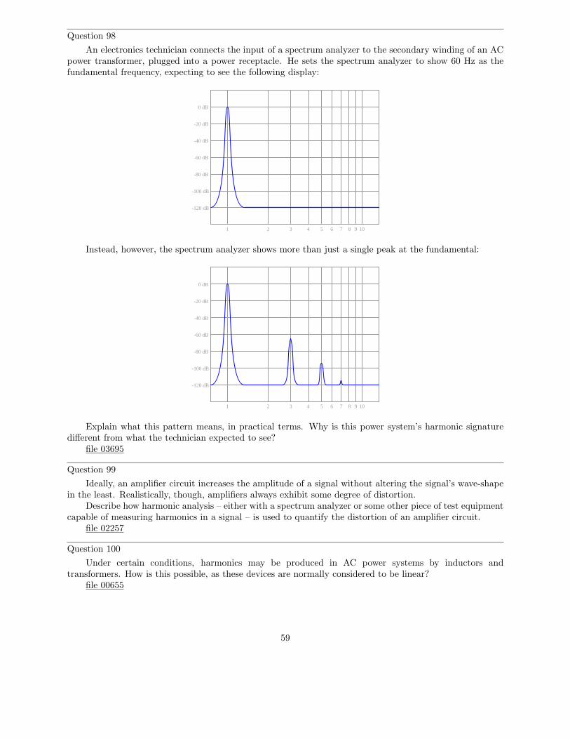
Question 98
An electronics technician connects the input of a spectrum analyzer to the secondary winding of an ACpower transformer, plugged into a power receptacle. He sets the spectrum analyzer to show 60 Hz as thefundamental frequency, expecting to see the following display:
0 dB
-20 dB
-40 dB
-60 dB
-80 dB
-100 dB
-120 dB
1 2 3 4 5 6 7 8 9 10
Instead, however, the spectrum analyzer shows more than just a single peak at the fundamental:
0 dB
-20 dB
-40 dB
-60 dB
-80 dB
-100 dB
-120 dB
1 2 3 4 5 6 7 8 9 10
Explain what this pattern means, in practical terms. Why is this power system’s harmonic signaturedifferent from what the technician expected to see?
file 03695
Question 99
Ideally, an amplifier circuit increases the amplitude of a signal without altering the signal’s wave-shapein the least. Realistically, though, amplifiers always exhibit some degree of distortion.
Describe how harmonic analysis – either with a spectrum analyzer or some other piece of test equipmentcapable of measuring harmonics in a signal – is used to quantify the distortion of an amplifier circuit.
file 02257
Question 100
Under certain conditions, harmonics may be produced in AC power systems by inductors andtransformers. How is this possible, as these devices are normally considered to be linear?
file 00655
59

Question 101
Identify some ways in which harmonics may be mitigated in AC power systems, since they tend to causetrouble for a variety of electrical components.
file 02261
Question 102∫
f(x) dx Calculus alert!
If both these circuits are energized by an AC sine-wave source providing a perfectly undistorted signal,the resulting output waveforms will differ in phase and possibly in amplitude, but not in shape:
Vout(diff) Vout(int)
Differentiator Integrator
If, however, the excitation voltage is slightly distorted, one of the outputs will be more sinusoidal thanthe other. Explain whether it is the differentiator or the integrator that produces the signal most resemblinga pure sine wave, and why.
Hint: I recommend building this circuit and powering it with a triangle wave, to simulate a mildlydistorted sine wave.
file 01600
60

Question 103
Note the effect of adding the second harmonic of a waveform to the fundamental, and compare thateffect with adding the third harmonic of a waveform to the fundamental:1st + 2nd Sum
1st + 3rd SumNow compare the sums of a fundamental with its fourth harmonic, versus with its fifth harmonic:1st + 4th Sum
1st + 5th SumAnd again for the 1st + 6th, versus the 1st + 7th harmonics:
61

1st + 6th Sum1st + 7th Sum
Examine these sets of harmonic sums, and indicate the trend you see with regard to harmonic numberand symmetry of the final (Sum) waveforms. Specifically, how does the addition of an even harmonic compareto the addition of an odd harmonic, in terms of final waveshape?
file 01892
Question 104
When technicians and engineers consider harmonics in AC power systems, they usually only considerodd-numbered harmonic frequencies. Explain why this is.
file 01893
62
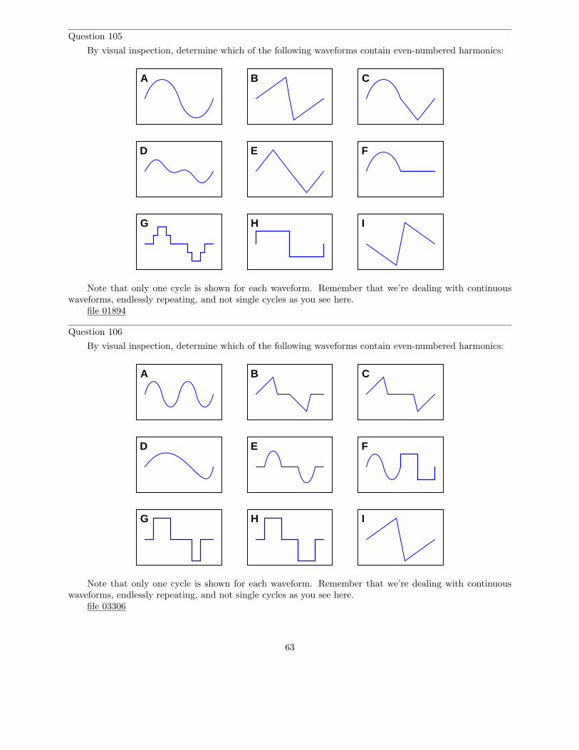
Question 105
By visual inspection, determine which of the following waveforms contain even-numbered harmonics:
A
E
B C
D F
G H I
Note that only one cycle is shown for each waveform. Remember that we’re dealing with continuouswaveforms, endlessly repeating, and not single cycles as you see here.
file 01894
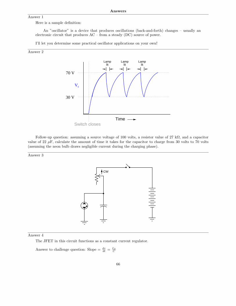
Question 106
By visual inspection, determine which of the following waveforms contain even-numbered harmonics:
A
E
B C
D F
G H I
Note that only one cycle is shown for each waveform. Remember that we’re dealing with continuouswaveforms, endlessly repeating, and not single cycles as you see here.
file 03306
63

Question 107
A crude measurement circuit for harmonic content of a signal uses a notch filter tuned to the fundamentalfrequency of the signal being measured. Examine the following circuit and then explain how you think itwould work:
VVoltmeter(calibrated
in dB)
Cal
Test
Cal
Test
Notchfilter
Testsignalsource
file 03455
Question 108
A radio antenna possesses both parasitic capacitance and distributed inductance, distributed along itsentire length:
Earth (ground)
C C
L
Long-wire antenna
Ideally, an antenna only exhibits these electrical properties, with no resistance. What does this suggestabout the electrical behavior of an antenna, especially compared to the behavior of other LC circuits youare familiar with?
file 02279
Question 109
When performing tests on a radio transmitter, it is often necessary to do so without actually broadcastinga signal through an antenna. In such scenarios, an equivalent resistor is connected to the output of thetransmitter instead of an actual antenna. If chosen properly, the resistor ”looks” the same as an antennafrom the perspective of the transmitter.
Explain how this is possible, since real antennae are built to have as little resistance as possible. Howcan a resistor adequately substitute for an antenna, which is nothing like a resistor in either construction orpurpose?
file 03457
64

Question 110
Calculate the theoretical length for a ”half-wave” antenna, assuming a transmitter ”carrier” frequencyof 105.3 MHz:
λ/2
RF transmitter
Also, calculate the practical antenna length considering the ”end effect,” which makes the antenna’selectrical length slightly different from its physical length (assume a K factor of 0.95).
file 02281
Question 111
Radio communication functions on the general principle of high-frequency AC power being modulatedby low-frequency data. Two common forms of modulation are Amplitude Modulation (AM) and FrequencyModulation (FM). In both cases, the modulation of a high frequency waveform by a lower-frequency waveformproduces something called sidebands.
Describe what ”sidebands” are, to the best of your ability.file 00654
65
Answers
Answer 1
Here is a sample definition:
An ”oscillator” is a device that produces oscillations (back-and-forth) changes – usually anelectronic circuit that produces AC – from a steady (DC) source of power.
I’ll let you determine some practical oscillator applications on your own!
Answer 2
Time
Vc
Switch closes
30 V
70 V
Lamplit
Lamplit
Lamplit
Follow-up question: assuming a source voltage of 100 volts, a resistor value of 27 kΩ, and a capacitorvalue of 22 µF, calculate the amount of time it takes for the capacitor to charge from 30 volts to 70 volts(assuming the neon bulb draws negligible current during the charging phase).
Answer 3
CW
Answer 4
The JFET in this circuit functions as a constant current regulator.
Answer to challenge question: Slope = dvdt
= ID
C
66

Answer 5
The heart of the oscillator circuit is unijunction transistor Q1. Together with some other components(I’ll let you figure out which!), this transistor forms a relaxation oscillator circuit. R1, R2, and C1 havedirect influence over the oscillation frequency.
Challenge question: what purpose does resistor R2 serve? It would seem at first glance that it servesno useful purpose, as potentiometer R1 is capable of providing any desired amount of resistance for the RCtime constant circuit on its own – R2’s resistance is simply added to it. However, there is an important,practical reason for including R2 in the circuit. Explain what that reason is.
Answer 6
A square-wave output signal may be obtained at the collector of either transistor. I’ll let you researchthis circuit’s principle of operation.
Answer 7
I won’t answer this question directly, but I will give a large hint: C1 and R2 determine the pulse widthof one-half of the square wave, while C2 and R3 control the pulse width of the other half:
C1 and R2
C2 and R3
Challenge question: re-draw the schematic diagram to show how a potentiometer could be used to makethe duty cycle adjustable over a wide range.
Answer 8
The amplifier receives positive feedback from the output (speaker) to the input (microphone).
Answer 9
The feedback network in this circuit must provide 180 degrees of phase shift, in order to sustainoscillations.
So long as the feedback network contains the correct types of components (resistors, capacitors, and/orinductors) in a working configuration, the components’ values will not alter the amount of phase shift, onlythe frequency of the oscillation.
Answer 10
The feedback network in this circuit must provide 0 degrees of phase shift, in order to sustain oscillations.
Answer 11
I’ll let you determine exactly what the ”Barkhausen” criterion is. If its value is less than 1, the oscillator’soutput will diminish in amplitude over time. If its value is greater than 1, the oscillator’s output will not besinusoidal!
67

Answer 12
The amplifier’s voltage gain must be (at least) +29.25 dB.
Answer 13
The amount of phase shift per RC section will be different in each circuit, as well as the operatingfrequency (given the same R and C component values).
Answer 14
Vout1 = 5.00 VAC RMS 6 0o
Vout2 = 3.33 VAC RMS 6 0o
Answer 15
It’s your luck day! Here, I show one method of solution:
R − j1
ωC= 2
(
11R
+ jωC
)
R − j1
ωC=
21R
+ jωC
(
R − j1
ωC
) (
1
R+ jωC
)
= 2
R
R+ jωRC − j
1
ωRC− j2 ωC
ωC= 2
1 + jωRC − j1
ωRC+ 1 = 2
jωRC − j1
ωRC= 0
jωRC = j1
ωRC
ωRC =1
ωRC
ω2 =1
R2C2
ω =1
RC
2πf =1
RC
f =1
2πRC
68

Answer 16
The potentiometer adjusts the Barkhausen criterion of the oscillator. I’ll let you figure out how to makethe frequency adjustable.
f = 153.9 Hz
Follow-up question: identify the paths of positive and negative feedback from the Wien bridge to thefirst amplifier stage.
Answer 17
This is a Hartley oscillator circuit, and the tank circuit establishes its frequency of operation.
f =1
2π√
L1C1
Follow-up question: calculate the operating frequency of this oscillator circuit if L1 = 330 mH and C1
= 0.15 µF.
Answer 18
This is a Colpitts oscillator circuit, and the tank circuit establishes its frequency of operation.
f =1
2π√
L1C1C2
C1+C2
Follow-up question: calculate the operating frequency of this oscillator circuit if L1 = 270 mH, C1 =0.047 µF, and C2 = 0.047 µF.
Answer 19
A ”crystal” is a chip of piezoelectric material that acts as an electromechanical tank circuit.
Answer 20
This is a Pierce oscillator circuit, and the crystal plays the same role that a tank circuit would in aHartley or Colpitts oscillator.
Answer 21
• 1st harmonic = 12 kHz• 2nd harmonic = 24 kHz• 3rd harmonic = 36 kHz• 4th harmonic = 48 kHz• 5th harmonic = 60 kHz• 6th harmonic = 72 kHz
Answer 22
Though it may seem strange to speak of it in such terms, an AC circuit ”views” a square wave as aninfinite series of sinusoidal harmonics.
Follow-up question: explain how this equivalence between a square wave and a particular series of sinewaves is a practical example of the Superposition Theorem at work.
69

Answer 23
“Any periodic waveform, no matter how complex, is equivalent to a series of sinusoidalwaveforms added together at different amplitudes and different frequencies, plus a DC component.”
Follow-up question: what does this equation represent?
f(t) = A0 + (A1 sin ωt) + (B1 cos ωt) + (A2 sin 2ωt) + (B2 cos 2ωt) + . . .
Answer 24
A spectrum analyzer.
Challenge questions: two similar instruments are the wave analyzer and the Fourier analyzer. Explainhow both these instruments are similar in function to a spectrum analyzer, and also how both differ.
Answer 25
The input signal is clean: a single peak at the 1 kHz mark. The amplifier’s output, on the other hand,is a bit distorted (i.e. no longer a perfect sine-wave shape as the input is).
Answer 26
Any feature (or fault) of the circuit causing imperfect signal reproduction will necessarily createharmonics, for it will turn a perfectly sinusoidal input signal into a distorted (non-perfect-sinusoidal) signal.
Answer 27
Any feature (or fault) of the amplifier portion of the oscillator circuit causing imperfect signalreproduction will necessarily create harmonics, for it will turn a perfectly sinusoidal input signal (fromthe LC network) into a distorted (non-perfect-sinusoidal) output signal.
Challenge question: Colpitts oscillators tend to produce ”purer” sine-wave outputs than Hartleyoscillators, all other factors being equal. Explain why.
Answer 28
The LP filter blocks all harmonics of the square wave except the fundamental (1st harmonic), resultingin a sinusoidal output.
Answer 29
Nonlinear loads.
Answer 30
Each series LC section is a resonant band-pass filter, tuned to successive harmonics of a 60 Hz sinewave. The selector switch enables a single voltmeter to measure the RMS amplitude of each harmonic.
Follow-up question: calculate the exact inductance values necessary for precise tuning of the five LCfilters, for the first five harmonics of a 60 Hz waveform.
Challenge question: the voltmeter in this circuit would not have to be a true-RMS meter. It couldsimply be an average-responding (RMS-calibrated) voltmeter and it would work the same. Explain why.
Answer 31
”RF” means Radio Frequency, implying a frequency of alternating current (AC) much greater than thatencountered in AC power or audio circuitry.
70
Answer 32
The fact that an piece of wire contains both inductance and capacitance means that it has the abilityto resonate just like any tank circuit!
Follow-up question: qualitatively estimate the frequency you suppose a length of wire would resonateat. Do you think fr would be a very low value (tens of hertz), a very high value (thousands, millions, orbillions of hertz), or somewhere in between? Keep in mind the equation for resonant frequency:
fr =1
2π√
LC
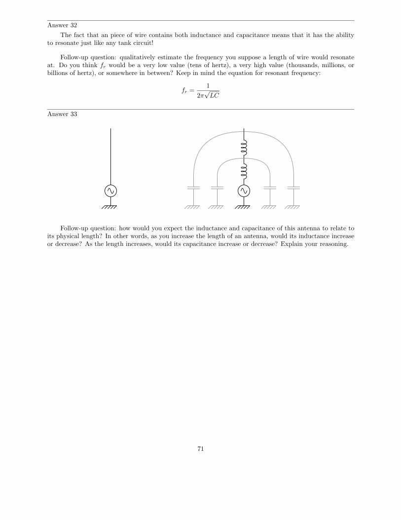
Answer 33
Follow-up question: how would you expect the inductance and capacitance of this antenna to relate toits physical length? In other words, as you increase the length of an antenna, would its inductance increaseor decrease? As the length increases, would its capacitance increase or decrease? Explain your reasoning.
71

Answer 34
Follow-up question: how would you expect the inductance and capacitance of this antenna to relate toits physical length? In other words, as you increase the length of an antenna, would its inductance increaseor decrease? As the length increases, would its capacitance increase or decrease? Explain your reasoning.
Answer 35
What James Clerk Maxwell predicted was the existence of electromagnetic waves, the lowest-frequencytype we commonly refer to as radio waves.
Follow-up question: name the scientist who first experimentally confirmed Maxwell’s prediction ofelectromagnetic waves.
Answer 36
Hertz’s experiment empirically demonstrated the theoretical discovery of James Clerk Maxwell, whoconcluded years before that ”electromagnetic waves” comprised of electric and magnetic fields oscillatingperpendicular to one another must be capable of radiating through empty space. This is the basis of radiocommunication: generating these electromagnetic waves for the purpose of communicating information overlong distances without wires.
Answer 37
Ideally you will need a device that produces both electric and magnetic fields in space: something thatpossesses both capacitance and inductance in an unshielded form where the electric and magnetic fieldswould be open to space. In other words, you will need an antenna.
Answer 38
Ideally, 100% of the energy input to an antenna leaves in the form of electromagnetic radiation.
Answer 39
A radio antenna will receive electromagnetic energy most efficiently if it is sized (tuned) to the exactfrequency of the desired radio waves.
72

Answer 40
λ ≈ 316 meters
I’ll let you find the equation on your own!
Answer 41
Modulation is the act of impressing information onto an otherwise featureless stream of matter or energy,usually for the sake of communicating that information over a long distance. Radio is a very common exampleof modulation, but I’ll let you research a few more on your own!
Answer 42
Modulation is the impression of information onto an otherwise featureless stream of matter or energy.In this case, the modulation of a smoke stream by blanket motions should be rather evident.
Answer 43 Modulated signal
TimeAnswer 44
I’ll let you figure this one out on your own!
73

Answer 45 Modulated signal
TimeAnswer 46
A VCO generates an AC output signal whose frequency is proportional to an externally-supplied inputvoltage.
Answer 47
As voltage across the varactor diode changes, its capacitance changes.The output frequency increases as the control voltage becomes more positive.
Answer 48
To understand how the JFETs are functioning in this VCO design, closely examine the ”saturation”regions of a JFET’s characteristic curves. Note that these regions appear as nearly straight-line sections.This indicates something about the behavior of a saturated JFET that is exploited in this VCO circuit.
The output frequency decreases as the control voltage becomes more positive.
Answer 49
Radio interference manifests itself as additional peaks on the ”envelope” of a modulated carrier wave.AM reception is based on the extraction of that envelope from the modulated carrier, and so AM receiverswill ”pick up” unwanted noise. FM reception is based on the extraction of information from changes infrequency, which is largely unaffected by noise.
74

Answer 50
There are several reasons you would not want to try to broadcast electromagnetic (radio) waves at audiofrequencies. A few of the most important are listed here:
• The necessary size of the antenna.• Low transmission efficiency from inability to match antenna length to (changing) audio frequency.• Interference from other (similar) radio transmitters.
Be prepared to explain why each of these factors effectively prohibits radio broadcasts at audiofrequencies.
Answer 51
Use circuit simulation software to verify your predicted and measured parameter values.
Answer 52
Use circuit simulation software to verify your predicted and measured parameter values.
Answer 53
Use circuit simulation software to verify your predicted and measured parameter values.
Answer 54
Use circuit simulation software to verify your predicted and measured parameter values.
Answer 55
Use circuit simulation software to verify your predicted and measured parameter values.
Answer 56
I do not provide a grading rubric here, but elsewhere.
Answer 57
Be sure to document all steps taken and conclusions made in your troubleshooting!
Answer 58
• Capacitor C1 fails open: Constant (unblinking) light from the neon bulb.
• Capacitor C1 fails shorted: No light from the bulb at all.
• Resistor R1 fails open: No light from the bulb at all.
• Solder bridge (short) past resistor R1: Very bright, constant (unblinking) light from the bulb, possiblebulb failure resulting from excessive current.
75

Answer 59
• Capacitor C1 fails open: No light from flash tube, possible failure of transformer primary winding and/ortransistor Q4 due to overheating.
• Capacitor C1 fails shorted: No light from flash tube.
• Resistor R2 fails open: No light from flash tube.
• Solder bridge (short) past resistor R2: Faster strobe rate for any given position of potentiometer R1,possibility of adjusting the strobe rate too high where the flash tube just refuses to flash.
• Resistor R4 fails open: No light from flash tube.
• Transistor Q4 fails open (collector-to-emitter): No light from flash tube.
• Capacitor C2 fails open: Possible damage to transistor Q4 from excessive transient voltages.
• Capacitor C2 fails shorted: No light from flash tube, Q4 will almost certainly fail due to overheating.
Answer 60
• Capacitor C1 fails shorted: No oscillation, low DC voltage output.
• Resistor R1 fails open: No oscillation, low DC voltage output.
• JFET fails shorted (drain-to-source): Oscillation waveform looks ”rounded” instead of having a straightleading edge, frequency is higher than normal.
• Resistor R3 fails open: No oscillation, high DC voltage output.
Answer 61
• Capacitor C1 fails open: Q2 immediately on, Q1 on after short time delay.
• Capacitor C2 fails open: Q1 immediately on, Q2 on after short time delay.
• Resistor R1 fails open: Q2 on, Q1 will have base current but no collector current.
• Resistor R2 fails open: Q1 on, Q2 off.
• Resistor R3 fails open: Q2 on, Q1 off.
• Resistor R4 fails open: Q1 on, Q2 will have base current but no collector current.
76

Answer 62
• Resistor R4 fails open: Zero volts DC and AC at all four test points except for TP3 where there will benormal DC bias voltage.
• Resistor R5 fails open: Normal signal at TP1, zero volts AC and DC at all other test points except forTP3 where there will be normal DC bias voltage.
• Resistor R7 fails open: Normal signals at TP1 and at TP2, zero volts AC and DC at all other test pointsexcept for TP3 where there will be normal DC bias voltage.
• Resistor R9 fails open: Normal signals at TP1, at TP2, and at TP3, but zero volts AC and DC at Vout.
• Capacitor C7 fails shorted: Normal AC signals at TP1, at TP2, and at TP3, badly distorted waveformat Vout, only about 0.7 volts DC bias at TP3.
• Capacitor C4 fails shorted: Normal signal at TP1, zero volts AC and DC at all other test points exceptfor TP3 where there will be normal DC bias voltage.
• Capacitor C5 fails open: Normal signals at TP1 and at TP2, zero volts AC and DC at all other testpoints except for TP3 where there will be normal DC bias voltage.
• Transistor Q3 fails open (collector-to-emitter): Normal signals at TP1 and at TP2, zero volts AC andDC at all other test points except for TP3 where there will be normal DC bias voltage.
Answer 63
Note: The fault list shown here is not comprehensive.
• Solder bridge shorting across any of the phase-shift resistors (R1 through R3).• Resistor R4 failing open.• Transistor Q1 failing in any mode.
Follow-up question: how would you rank the listed faults in order of probability? In other words, whichof these faults do you suppose would be more likely than the others, least likely than the others, etc.?
Answer 64
A partially shorted primary winding will result in increased frequency and (possibly) increased distortionin the output signal. A partially shorted secondary winding may result in oscillations ceasing altogether!
Answer 65
• Capacitor C1 fails open: Output frequency increases.
• Inductor L1 fails open: Output frequency decreases.
• Resistor R1 fails open: Output frequency decreases.
• Resistor R2 fails open: Output frequency increases.
• Inductor L2 fails partially shorted: Output frequency increases.
Answer 66
Left is NPN, and right is PNP.
Answer 67
I strongly suspect a bad diode. Explain why a defective diode would cause the transistor to failprematurely, and specifically what type of diode failure (open or shorted) would be necessary to causethe transistor to fail in this manner.
77

Answer 68
Ztotal =√
R2 + X2
Answer 69
R = 2.2 kΩ
XC = 2.067 kΩ
Ztotal = 3.019 kΩ
Scalar calculationsR = 2.2 kΩ XC = 2.067 kΩ
Zseries =√
R2 + XC2
Zseries =√
22002 + 20672 = 3019 Ω
Complex number calculationsZR = 2.2 kΩ 6 0o ZC = 2.067 kΩ 6 − 90o (Polar form)ZR = 2.2 kΩ + j0 Ω ZC = 0 Ω − j2.067 kΩ (Rectangular form)
Zseries = Z1 + Z2 + · · ·Zn (General rule of series impedances)Zseries = ZR + ZC (Specific application to this circuit)
Zseries = 2.2 kΩ 6 0o + 2.067 kΩ 6 − 90o = 3.019 kΩ 6 − 43.2o
Zseries = (2.2 kΩ + j0 Ω) + (0 Ω − j2.067 kΩ) = 2.2 kΩ − j2.067 kΩ
Answer 70
VC = 47.56 volts peakVR = 6.508 volts peakI = 1.972 milliamps peakΘZ = −82.21o
Follow-up question: what would we have to do to get these answers in units RMS instead of units”peak”?
Answer 71
The proper angle in this circuit is Θ, and it will be a positive (leading) quantity.
Answer 72
Vout = 6.7 V 6 -47.9o
Answer 73
Vout = 2.593 V 6 61.3o
Answer 74
EC phase shift = -76.7o
Challenge question: what effect will a change in potentiometer setting have on this phase angle?Specifically, will increasing the resistance make the phase shift approach -90o or approach 0o?
78

Answer 75
f = 798 Hz
Answer 76
f = 6.54 kHz
Answer 77
f = 465 Hz
Answer 78
f = 929 Hz
Answer 79
The pendulum in a mechanical clock serves to regulate the frequency of the clock’s ticking. The electricalequivalent of a pendulum is a tank circuit.
Answer 80
This circuit is a simple ”CW” radio transmitter, used to broadcast information using Morse code.The second technician is closer to the truth than the first, with regard to the capacitor. C1 is not part of
the oscillator’s resonant network, and so does not set the oscillation frequency. However, if the replacementcapacitor’s value is too far from the original’s value, this circuit will not start and stop oscillating as ”crisply”as it did before, when the code key switch is repeatedly actuated.
Answer 81
The feedback network in this circuit must provide 180 degrees of phase shift, in order to sustainoscillations.
Answer 82
The feedback network in this circuit must provide 360 degrees of phase shift, in order to sustainoscillations.
Answer 83
This is a Meissner oscillator circuit, and the tank circuit establishes its frequency of operation.
f =1
2π√
L1C1
79

Answer 84
This is a Clapp oscillator circuit, and the tank circuit establishes its frequency of operation.
f =1
2π
√
L1
(
11
C1+ 1
C2+ 1
C3
)
Follow-up question: you may notice that the Clapp oscillator is just a variation of the Colpittsoscillator design. If C3 is much smaller than either C1 or C2, the frequency stability of the oscillatorcircuit will be relatively unchanged by variations in parasitic capacitance throughout the circuit (especiallytransistor junction ”Miller effect” capacitances). Explain why, and how the following equation provides anapproximation of operating frequency under these conditions:
f ≈1
2π√
L1C3
Answer 85
This is an Armstrong oscillator circuit, and the combination of capacitor C3 and primary transformerwinding inductance L1 establishes its frequency of operation.
f =1
2π√
L1C3
+V
R1
R2
C2RC
RE CE
C1
C3 L1 L2
80

Answer 86
+V
R1
R2
C1
L1
C2Xtal
Crystal-controlledHartley oscillator
RC
RE CE
Follow-up question: does the resonant frequency of the tank circuit have to match the crystal’s resonantfrequency? Why or why not?
Answer 87
Q values of several thousand are commonplace with crystals, while Q values in excess of 10 are consideredgood for LC tank circuits!
Answer 88
Here is a re-drawn representation of the amplifier circuit, with the base-emitter capacitance shown:
-V
+V
Rinput
Lstray
Cload
RC
RE
CBE
Follow-up question: what type of oscillator circuit does this resemble?
Challenge question: what type(s) of load would tend to make this circuit oscillate more readily thanothers?
81

Answer 89
f = 159.155 Hz
If the feedback signal comes from the other side of the bridge, the feedback signal’s phase shift will bedetermined by a different set of components (primarily, the coupling capacitors and bias network resistances)rather than the reactive arms of the bridge.
Answer 90
• Square wave oscillator: R1 through R4, C1 and C2, Q1 and Q2
• First integrator stage: R5 and C3
• Second integrator stage: R6 and C4
• Buffer stage (current amplification): Q3 and R7
• Final gain stage (voltage amplification): R8 and R9, Rpot, Q4, and C7
Answer 91
• 1st harmonic = 60 Hz• 2nd harmonic = 120 Hz• 3rd harmonic = 180 Hz• 4th harmonic = 240 Hz• 5th harmonic = 300 Hz• 6th harmonic = 360 Hz
Answer 92
• 1 octave greater than the fundamental = 2 kHz• 2 octaves greater than the fundamental = 4 kHz• 3 octaves greater than the fundamental = 8 kHz• 4 octaves greater than the fundamental = 16 kHz• 5 octaves greater than the fundamental = 32 kHz• 6 octaves greater than the fundamental = 64 kHz
Answer 93
200 Hz 600 Hz 1 kHz 1.4 kHz9 V RMS 3 V RMS 1.8 V RMS 1.29 V RMS
≈ vsquare
82
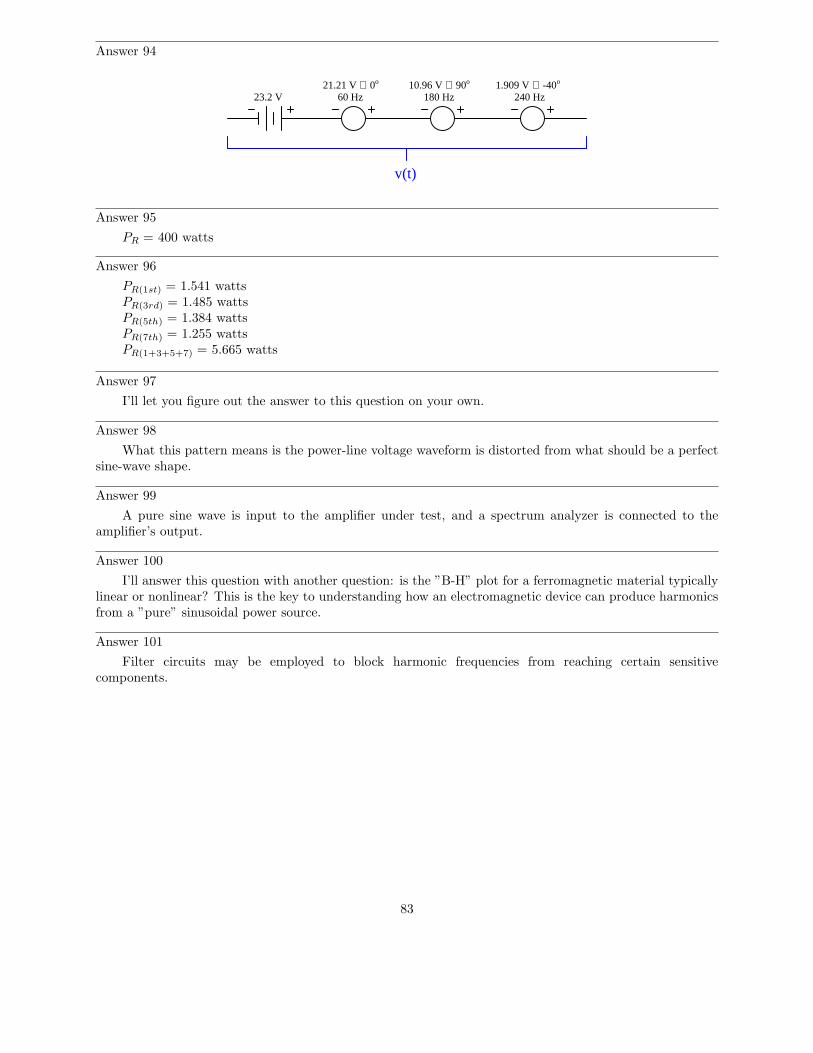
Answer 94
v(t)
23.2 V21.21 V ∠ 0o
60 Hz 180 Hz 240 Hz10.96 V ∠ 90o 1.909 V ∠ -40o
Answer 95
PR = 400 watts
Answer 96
PR(1st) = 1.541 wattsPR(3rd) = 1.485 wattsPR(5th) = 1.384 wattsPR(7th) = 1.255 wattsPR(1+3+5+7) = 5.665 watts
Answer 97
I’ll let you figure out the answer to this question on your own.
Answer 98
What this pattern means is the power-line voltage waveform is distorted from what should be a perfectsine-wave shape.
Answer 99
A pure sine wave is input to the amplifier under test, and a spectrum analyzer is connected to theamplifier’s output.
Answer 100
I’ll answer this question with another question: is the ”B-H” plot for a ferromagnetic material typicallylinear or nonlinear? This is the key to understanding how an electromagnetic device can produce harmonicsfrom a ”pure” sinusoidal power source.
Answer 101
Filter circuits may be employed to block harmonic frequencies from reaching certain sensitivecomponents.
83

Answer 102
The differentiator circuit will output a much more distorted waveshape, because differentiation magnifiesharmonics:
d
dt(sin t) = cos t
d
dt(sin 2t) = 2 cos 2t
d
dt(sin 3t) = 3 cos 3t
d
dt(sin 4t) = 4 cos 4t
· · ·
d
dt(sin nt) = n cos nt
Answer 103
The addition of an even harmonic introduces asymmetry about the horizontal axis. The addition of oddharmonics does not.
Challenge question: explain why this is the case, any way you can.
Answer 104
Nonlinear loads are usually (but not always!) symmetrical in their distortion.
Answer 105
The following waveforms contain even-numbered harmonics: B, C, D, F, and I. The rest only containodd harmonics of the fundamental.
Answer 106
The following waveforms contain even-numbered harmonics: C, D, G, and I. The rest only contain oddharmonics of the fundamental.
Answer 107
If the signal source is pure (no harmonics), the voltmeter will register nothing (negative infinite decibels)when the switch is flipped to the ”test” position.
Answer 108
A radio antenna has a resonant frequency, just like an LC circuit.
Follow-up question: what physical variable(s) determines the resonant frequency of an antenna?
Answer 109
Although an antenna has little actual resistance, it does radiate energy into space, just like a resistordissipates energy in the form of heat. The only significant difference is that an antenna’s radiation is in theform of electromagnetic waves at the same frequency as the transmitter output.
84

Answer 110(
λ2
)
theoretical= 1.425 meters
(
λ2
)
practical= 1.353 meters
Answer 111
”Sidebands” are sinusoidal frequencies just above and just below the carrier frequency, produced as aresult of the modulation process. On a spectrum analyzer, they show up as peaks to either side of the main(carrier) peak. Their quantity, frequencies, and amplitudes are all a function of the data signals modulatingthe carrier.
85
Notes
Notes 1
Oscillators are nearly ubiquitous in a modern society. If your students’ only examples are electronic innature, you may want to mention these mechanical devices:
• Pendulum clock mechanism• Shaker (for sifting granular materials or mixing liquids such as paint)• Whistle• Violin string
Notes 2
What we have here is a very simple strobe light circuit. This circuit may be constructed in the classroomwith minimal safety hazard if the DC voltage source is a hand-crank generator instead of a battery bankor line-powered supply. I’ve demonstrated this in my own classroom before, using a hand-crank ”Megger”(high-range, high-voltage ohmmeter) as the power source.
Notes 3
Ask your students to explain why the potentiometer has the speed-changing effect it does on the circuit’sflash rate. Would there be any other way to change this circuit’s flash rate, without using a potentiometer?
Notes 4
Ask your students how they would know to relate ”constant current” to the peculiar charging action ofthis capacitor. Ask them to explain this mathematically.
Then, ask them to explain exactly how the JFET works to regulate charging current.Note: the schematic diagram for this circuit was derived from one found on page 958 of John
Markus’ Guidebook of Electronic Circuits, first edition. Apparently, the design originated from a Motorolapublication on using unijunction transistors (”Unijunction Transistor Timers and Oscillators,” AN-294,1972).
Notes 5
Ask your students to explain what the other transistors do in this circuit. If time permits, explore theoperation of the entire circuit with your students, asking them to explain the purpose and function of allcomponents in it.
After they identify which components control the frequency of oscillation, ask them to specificallyidentify which direction each of those component values would need to be changed in order to increase (ordecrease) the flash rate.
Notes 6
Ask your students to explain how the frequency of this circuit could be altered. After that, ask themwhat they would have to do to alter the duty cycle of this circuit’s oscillation.
Notes 7
Astable multivibrator circuits are simple and versatile, making them good subjects of study anddiscussion for your students.
Notes 8
Ask your students to define what ”positive feedback” is. In what way is the feedback in this system”positive,” and how does this feedback differ from the ”negative” variety commonly seen within amplifiercircuitry?
86

Notes 9
Ask your students to explain why the feedback network must provide 180 degrees of phase shift to thesignal. Ask them to explain how this requirement relates to the need for regenerative feedback in an oscillatorcircuit.
The question and answer concerning feedback component selection is a large conceptual leap for somestudents. It may baffle some that the phase shift of a reactive circuit will always be the proper amount toensure regenerative feedback, for any arbitrary combination of component values, because they should knowthe phase shift of a reactive circuit depends on the values of its constituent components. However, once theyrealize that the phase shift of a reactive circuit is also dependent on the signal frequency, the resolution tothis paradox is much easier to understand.
Notes 10
Ask your students to explain why the feedback network must provide 180 degrees of phase shift to thesignal. Ask them to explain how this requirement relates to the need for regenerative feedback in an oscillatorcircuit.
The question and answer concerning feedback component selection is a large conceptual leap for somestudents. It may baffle some that the phase shift of a reactive circuit will always be the proper amount toensure regenerative feedback, for any arbitrary combination of component values, because they should knowthe phase shift of a reactive circuit depends on the values of its constituent components. However, once theyrealize that the phase shift of a reactive circuit is also dependent on the signal frequency, the resolution tothis paradox is much easier to understand.
Notes 11
The question of ”What is the Barkhausen criterion” could be answered with a short sentence, memorizedverbatim from a textbook. But what I’m looking for here is real comprehension of the subject. Have yourstudents explain to you the reason why oscillation amplitude depends on this factor.
Notes 12
This question probes students’ comprehension of the Barkhausen criterion: that total loop gain mustbe equal or greater than unity in order for sustained oscillations to occur.
Notes 13
In either case, the point of the RC stages is to phase-shift the feedback signal by 180o. It is an over-simplification, though, to say that each stage in the three-section circuit shifts the signal by 60, and/or thateach stage in the four-section circuit shifts the signal by 45o. The amount of phase-shift in each section willnot be equal (with equal R and C values) due to the loading of each section by the previous section(s).
Notes 14
This question provides an excellent opportunity for your students to review AC circuit analysis, as wellas pave the way for questions regarding Wien bridge oscillator circuits!
87

Notes 15
I chose to show the method of solution here because I find many of my students weak in manipulatingimaginary algebraic terms (anything with a j in it). The answer is not exactly a give-away, as students stillhave to figure out how I arrived at the first equation. This involves both an understanding of the voltagedivider formula as well as the algebraic expression of series impedances and parallel admittances.
It is also possible to solve for the frequency by only considering phase angles and not amplitudes. Sincethe only way Vout2 can have a phase angle of zero degrees in relation to the excitation voltage is for theupper and lower arms of that side of the bridge to have equal impedance phase angles, one might approachthe problem in this fashion:
θ = tan−1
(
Xseries
Rseries
)
θ = tan−1
(
Bparallel
Gparallel
)
Xseries
Rseries
=Bparallel
Gparallel
You might try presenting this solution to your students if imaginary algebra is too much for them atthis point.
Notes 16
One of the advantages of the Wien bridge circuit is its ease of adjustment in this manner. Usinghigh-quality capacitors and resistors in the other side of the bridge, its output frequency will be very stable.
Notes 17
Ask your students to describe the amount of phase shift the tank circuit provides to the feedback signal.Also, ask them to explain how the oscillator circuit’s natural frequency may be altered.
Notes 18
Ask your students to describe the amount of phase shift the tank circuit provides to the feedback signal.Also, ask them to explain how the oscillator circuit’s natural frequency may be altered.
Notes 19
Ask your students to describe the phenomenon of piezoelectricity, and how this principle works insidean oscillator crystal. Also, ask them why crystals are used instead of tank circuits in so many precisionoscillator circuits.
Notes 20
Ask your students to explain how the oscillator circuit’s natural frequency may be altered. How doesthis differ from frequency control in either the Hartley or Colpitts designs?
Notes 21
Ask your students to determine the mathematical relationship between harmonic number, harmonicfrequency, and fundamental frequency. It isn’t difficult to figure out!
88

Notes 22
If you have access to a graphing calculator or a computer with graphing software installed, and aprojector capable of showing the resulting graph(s), you may demonstrate this square-wave synthesis infront of the whole class. It makes an excellent illustration of the concept.
Discuss this with your students: that the relatively simple rules of AC circuit analysis (calculatingreactance by ωL and 1
ωC, calculating impedance by the trigonometric sum of reactance and resistance,
etc.) can be applied to the analysis of a square wave’s effects if we repeat that analysis for every harmoniccomponent of the wave.
This is truly a remarkable principle, that the effects of a complex waveform on a circuit may bedetermined by considering each of that waveform’s harmonics separately, then those effects added together(superimposed) just as the harmonics themselves are superimposed to form the complex wave. Explain toyour students how this superposition principle is not limited to the analysis of square waves, either. Anycomplex waveform whose harmonic constituents are known may be analyzed in this fashion.
Notes 23
So far, all the ”tools” students have learned about reactance, impedance, Ohm’s Law, and such inAC circuits assume sinusoidal waveforms. Being able to equate any non-sinusoidal waveform to a series ofsinusoidal waveforms allows us to apply these ”sinusoidal-only” tools to any waveform, theoretically.
An important caveat of Fourier’s theorem is that the waveform in question must be periodic. That is,it must repeat itself on some fixed period of time. Non-repetitive waveforms do not reduce to a definiteseries of sinusoidal terms. Fortunately for us, a great many waveforms encountered in electronic circuits areperiodic and therefore may be represented by, and analyzed in terms of, definite Fourier series.
It would be good to mention the so-called FFT algorithm in this discussion while you’re on this topic: thedigital algorithm that computers use to separate any sampled waveform into multiple constituent sinusoidalfrequencies. Modern computer hardware is able to easily implement the FFT algorithm, and it finds extensiveuse in analytical and test equipment.
Notes 24
Spectrum analyzers capable of analyzing radio-frequency signals are very expensive, but low-costpersonal computer hardware and software does a good job of analyzing complex audio signals. It wouldbe a benefit to your class to have a low-frequency spectrum analyzer setup available for student use, andpossible demonstration during discussion.
Notes 25
The purpose of this question is to get students to realize the presence of harmonics means a departurefrom a once-perfect sinusoidal wave-shape. What used to be free of harmonics now contains harmonics, andthis indicates distortion of the sine wave somewhere within the amplifier.
By the way, the perfectly flat ”noise floor” at -120 dB is highly unusual. There will always be a ”rough”floor shown on the display of a spectrum analyzer, but this is not pertinent to the question at hand so Iomitted it for simplicity’s sake.
Notes 26
Discuss with your students the nature of harmonics: how multiple sinusoidal waveforms are necessarilycontained in any periodic waveform that is not perfectly sinusoidal itself.
Notes 27
Discuss with your students the nature of harmonics: how multiple sinusoidal waveforms are necessarilycontained in any periodic waveform that is not perfectly sinusoidal itself.
89

Notes 28
Ask your students what they think about the rolloff requirement for this LP filter. Will any LP filterwork, or do we need something special?
Notes 29
My answer to this question is intentionally vague. It is correct, but does not reveal anything about thereal nature of the cause, or more importantly, why a ”nonlinear” load would cause harmonics. Discuss withyour students what a ”nonlinear” device is, and what it does to a sinusoidal signal to generate harmonics.
Notes 30
This question provides students with some review of passive filter circuit theory, as well as insight intoa practical circuit they could conceivably build as a project.
A very important design feature of this circuit is the narrow bandwidth of each harmonic ”channel.”The filter pass-bands must not come close to overlapping, or else the meter response will not be exclusivelyindicative of the harmonic it is switched to. High Q values for each filter section ensure that the meter willonly register the particular harmonic that is selected for measurement.
Notes 31
Ask your students to list the frequencies of their favorite broadcast radio stations as an example of someradio frequencies. Show them a typical benchtop signal generator (non-RF) for comparison of frequencyrange, and they should begin to understand the concept.
Notes 32
If your students have difficulty knowing where to start with the follow-up question, ask them toqualitatively estimate the distributed L and C for a piece of wire, say, 10 feet long. Given the lack ofany high-permeability core material and the lack of any high-permittivity dielectric (just air), the answersfor both should be ”very small.” Then, ask them again how they would qualitatively rate the wire’s resonantfrequency.
Notes 33
Do not be surprised if some of your students ask whether or not an antenna is capable of resonating,since it possesses both inductance and capacitance. In fact, this is the subversive point of this question:to get students to realize that even a simple pair of wires may be considered a resonant system, and thento beg the question of what happens at resonance! The follow-up question suggests a relationship betweenphysical size and resonant frequency, by asking what happens to both L and C as length changes. Explorethese ideas with your students, and watch them gain a surprisingly deep understanding of how an antennaworks based on their knowledge of LC resonant circuits.
Notes 34
Do not be surprised if some of your students ask whether or not an antenna is capable of resonating,since it possesses both inductance and capacitance. In fact, this is the subversive point of this question:to get students to realize that even a simple pair of wires may be considered a resonant system, and thento beg the question of what happens at resonance! The follow-up question suggests a relationship betweenphysical size and resonant frequency, by asking what happens to both L and C as length changes. Explorethese ideas with your students, and watch them gain a surprisingly deep understanding of how an antennaworks based on their knowledge of LC resonant circuits.
90

Notes 35
Not only does this question relate the concept of radio waves to concepts your students should alreadybe familiar with (electric and magnetic fields), but it also introduces a piece of amazing scientific history.That radio waves were first predicted mathematically rather than discovered accidently by experiment isboth astonishing and enlightening.
You may find that one or more of your brighter students notice Maxwell’s prediction relates a changein one type of field to a static magnitude of the other (i.e. E ∝ dΦB
dtand B ∝ dΦE
dt), and that this makes
it difficult to see how one changing field could create another changing field. If anyone asks this question,point out to them that there is a set of similar mathematical functions related to one another by derivatives,and they are:
sin t = −d
dtcos t cos t =
d
dtsin t
Does anything look familiar (omitting the µ0I term from the second equation)?
∮
E · dl = −dΦB
dt
∮
B · dl = µ0ǫ0dΦE
dt
Since we know electric flux is related to electric field by geometry (ΦE =∫
E · dA) and magnetic flux isrelated to magnetic field by geometry as well (ΦB =
∫
B · dA), we may write the following proportionalities:
ΦE ∝ −dΦB
dtΦB ∝
dΦE
dt
Now do things look similar to the sine/cosine derivative relationship? Thus, if the electric flux ΦE
oscillates as a sine wave, the magnetic flux ΦB will oscillate as a cosine wave, and so on.
Notes 36
An experiment such as this is not difficult to set up. Be sure to provide the appropriate safety precautionsagainst electric shock, as such spark-gap transmitters (as they came to be called) require substantially highvoltages to operate.
Notes 37
The purpose of this question is to relate the concept of distributed capacitance and inductance alonga plain piece of wire to the very nature of electromagnetic waves (oscillating electric and magnetic fields).If students suggest using capacitors and inductors, they are quite close to the mark. Unfortunately, thesedevices are usually designed to contain their respective fields to prevent radiation into space. Here, we wantthe fields to radiate away from the device, and so we use an open wire (or an array of open wires).
Notes 38
Although students may have some to associate the concept of ”dissipation” exclusively with resistors,this is not entirely correct. All that is meant by ”dissipation” is the dispersal of energy; that is, energyleaving an electric circuit and not returning. With resistors, this occurs in the form of heat, but this is notthe only kind of dissipation! In electric motors, most of the energy is dissipated in the form of mechanicalenergy, which goes into doing work (and some heat, of course). Light bulbs dissipate energy in the form oflight, not just heat.
Notes 39
The analogy of a goblet shattered by sound waves helps students readily identify with a concept that isotherwise abstract: the reception of electromagnetic waves by an antenna. Ask your students to relate thematching of frequencies to the transmission of radio waves as well as the reception of them.
91

Notes 40
I purposely omit the velocity of light, as well as the time/distance/velocity equation, so that studentswill have to do some simple research this calculate this value. Neither of these concepts is beyond high-schoollevel science students, and should pose no difficulty at all for college-level students to find on their own.
Notes 41
There are many examples of modulation that students can find for presentation, and not all of them areelectronic. Challenge them to think of scenarios other than modern electronic and/or optical communicationschemes where modulation of some kind is employed.
Notes 42
It is important for students to understand that modulation is not limited to electronic media. Strangerexamples than this may be cited as proof. I once spoke with an engineer specializing in vibration measurementwho told me of a very odd application of modulation for data communication. He worked on the design ofa vibration sensor that would be embedded in the head of an oil well drill bit. This sensor was supposed totransmit information to the surface, thousands of feet up, but could not use radio or any other ”normal”data media because of the distances involved and the harsh environment. The solution taken to this uniqueproblem was to have the sensor activate a valve at the drill head which would modulate the flow of drillingmud up to the surface: a byproduct of the drilling process that had to be pumped up to the surface anyway.By pulsing the normally steady mud flow, digital data could be communicated to pressure sensors at thesurface, and then converted into binary data for a computer to archive and translate. Granted, the bit ratewas very slow, but the system worked.
An application like this shows how important it is for students to exercise creativity. The reallyinteresting problems in life do not yield to ”tried and true” solutions, but can only be overcome throughthe exercise of creativity and skill. Do everything you can to expose your students to such creative thinkingwithin their discipline(s), and this will help them to become the problem-solvers of tomorrow!
Notes 43
I do not expect that students will be able to precisely sketch the modulated waveform, especially whenthe period of the carrier is so short. However, they should be able to express the general idea of amplitudemodulation in some form of drawing or sketch, and that’s all I’m interested in seeing from them in responseto this question.
92

Notes 44
Multiplier circuits are quite useful, and not just for amplitude modulation. The fact that they can beused as amplitude modulators, though, is a concept some students find hard to understand. One illustrationthat might clear things up is an adjustable voltage divider (since multiplication and division are very closelyrelated):
Modulating signal
Carrier signalAM output
(changing position of potentiometeraccording to modulating signal value)
Now, such a potentiometer circuit would be totally impractical for any modulating signal frequencymeasured in Hertz, as the potentiometer would wear out very rapidly from all the motion. It is the principleof modulated voltage division that this circuit helps to communicate, though. Multiplier circuits do the samething, only multiplying the amplitude of the carrier signal rather than dividing it.
Notes 45
I do not expect that students will be able to precisely sketch the modulated waveform, especially whenthe period of the carrier is so short. However, they should be able to express the general idea of frequencymodulation in some form of drawing or sketch, and that’s all I’m interested in seeing from them in responseto this question.
Notes 46
Note to your students that VCO circuits are not just used in FM radio transmission. They are alsoessential to the function of phase-locked loops.
Notes 47
This question is a good review of varactor diode function, as well as frequency modulation theory.
Notes 48
Not only does this question allow students to examine the workings of a VCO, but it also provides agood review of JFET theory, as well as a practical example of a special application of junction field-effecttransistors.
Note: the schematic diagram for this circuit was derived from one found on page 997 of JohnMarkus’ Guidebook of Electronic Circuits, first edition. Apparently, the design originated from a Motorolapublication on using field effect transistors (”Low Frequency Applications of Field-Effect Transistors,” AN-511, 1971).
Notes 49
Ask students to explain this principle in their own words, and not just repeat the given answer.
Notes 50
The purpose of this question is to have students relate their understanding of basic RF and antennatheory to a very practical problem of broadcasting low-frequency (in this case, audio) information. A funexercise to do along with this question is to calculate the necessary physical dimensions of a quarter-wave(λ
4 ) antenna at a frequency of 2 kHz, keeping in mind that λ = vf
and v ≈ 3 × 10⁸ meters per second.
93
Notes 51
Use a variable-voltage, regulated power supply to supply any amount of DC voltage below 30 volts.Specify standard resistor values, all between 1 kΩ and 100 kΩ (1k5, 2k2, 2k7, 3k3, 4k7, 5k1, 6k8, 10k, 22k,33k, 39k 47k, 68k, etc.).
This circuit produces nice, sharp-edged square wave signals at the transistor collector terminals whenresistors R1 and R4 are substantially smaller than resistors R2 and R3. This way, R2 and R3 dominate thecapacitors’ charging times, making calculation of duty cycle much more accurate. Component values I’veused with success are 1 kΩ for R1 and R4, 100 kΩ for R2 and R3, and 0.1 µF for C1 and C2.
An extension of this exercise is to incorporate troubleshooting questions. Whether using this exercise asa performance assessment or simply as a concept-building lab, you might want to follow up your students’results by asking them to predict the consequences of certain circuit faults.
Notes 52
Use a variable-voltage, regulated power supply to supply any amount of DC voltage below 30 volts.Specify standard resistor values, all between 1 kΩ and 100 kΩ (1k5, 2k2, 2k7, 3k3, 4k7, 5k1, 6k8, 10k, 22k,33k, 39k 47k, 68k, etc.).
Rpot serves the purpose of providing variable AC gain in the first amplifier stage to meet the Barkhausencriterion.
I have had good success with the following values:
• VCC = 12 volts• C1 and C2 = 0.001 µF• C3 = 47 µF• C4 = 0.47 µF• R1 and R2 = 4.7 kΩ• R3 = 4.7 kΩ• R4 = 39 kΩ• R5 = 22 kΩ• R6 = 27 kΩ• R7 = 3.3 kΩ• Rpot = 10 kΩ, linear• Q1 and Q2 = part number 2N2222
An extension of this exercise is to incorporate troubleshooting questions. Whether using this exercise asa performance assessment or simply as a concept-building lab, you might want to follow up your students’results by asking them to predict the consequences of certain circuit faults.
94
Notes 53
I have had great success with the following values:
• VCC = 7 to 24 volts• C1 and C2 = 0.22 µF• C3 = 0.47 µF• L1 = 100 µH (ferrite core RF choke)• R1 = 22 kΩ• R2 = 1.5 MΩ• Q1 = part number 2N3403
With these component values, the output waveform was quite clean and the frequency was very closeto predicted:
fout =1
2π√
LC1C2
C1+C2
You might want to quiz your students on the purpose of resistor R2, since it usually only has to bepresent at power-up to initiate oscillation!
An extension of this exercise is to incorporate troubleshooting questions. Whether using this exercise asa performance assessment or simply as a concept-building lab, you might want to follow up your students’results by asking them to predict the consequences of certain circuit faults.
Notes 54
I have had great success with the following values:
• +V = 7 to 24 volts• C1 and C2 = 0.001 µF• C3, C4, and C5 = 0.47 µF• L1 = 100 µH (ferrite core RF choke)• R1 = 22 kΩ• R2 = 1.5 MΩ• R3 = 6.8 kΩ• R4 = 100 kΩ• Q1 = part number 2N3403• Q2 = part number MPF 102
With these component values, the carrier waveform was quite clean and the frequency was almost exactly700 kHz:
fout =1
2π√
LC1C2
C1+C2
Modulation isn’t that great, due to the crude nature of the circuit, but it is certainly good enough tohear over an appropriately tuned AM radio. Setting Vsignal and fsignal is a matter of experimentation, toachieve the desired degree of modulation and tone pitch.
An extension of this exercise is to incorporate troubleshooting questions. Whether using this exercise asa performance assessment or simply as a concept-building lab, you might want to follow up your students’results by asking them to predict the consequences of certain circuit faults.
95

Notes 55
Use a variable-voltage, regulated power supply to supply any amount of DC voltage below 30 volts.Specify standard resistor values, all between 1 kΩ and 100 kΩ (1k5, 2k2, 2k7, 3k3, 4k7, 5k1, 6k8, 10k, 22k,33k, 39k 47k, 68k, etc.).
This circuit demonstrates the use of passive integrators to convert a square wave into a pseudo-sine waveoutput. The multivibrator portion produces nice, sharp-edged square wave signals at the transistor collectorterminals when resistors R1 and R4 are substantially smaller than resistors R2 and R3. Component valuesI’ve used with success are 1 kΩ for R1 and R4, 100 kΩ for R2 and R3, and 0.001 µF for C1 and C2.
Resistors R5 and R6, along with capacitors C3 and C4, form a dual passive integrator network tore-shape the square-wave output of the multivibrator into a pseudo-sine wave. These components’ valuesmust be chosen according to the multivibrator frequency, so that the integration is realistic without theattenuation being excessive. Integrator component values that have worked well for the multivibratorcomponents previously specified are 10 kΩ for R5 and R6, and 0.1 µF for C3 and C4.
Transistor Q3 is just an emitter follower, placed there to give the amplifier section a high inputimpedance. Q3’s emitter resistor value is not critical. I have used a 1 kΩ resistor for R7 with good success.
The last transistor (Q4) is for voltage amplification. A ”trimmer” style potentiometer (10 kΩrecommended for Rpot) provides easy adjustment of biasing for different supply voltages. Using thepotentiometer, I have operated this circuit on supply voltages ranging from -6 volts to -27 volts. Use abypass capacitor (C7) large enough that its reactance at the operating frequency is negligible (less than1 ohm is good), such as 33 µF. Resistor values I’ve used with success are 10 kΩ for R8 and 4.7 kΩ forR9. Coupling capacitor values are not terribly important, so long as they present minimal reactance at theoperating frequency. I have used 0.47 µF for both C5 and C6 with good success.
You may find that the relatively high operating frequency of this circuit complicates matters with regardto parasitic capacitances. The fast rise and fall times of the strong square wave tend to couple easily to thesine-wave portions of the circuit, especially when the sine wave signal is so severely attenuated by the doubleintegrators. One solution to this dilemma is to lower the operating frequency of the circuit, allowing a lowercutoff frequency for the double integrator (two-pole lowpass filter) section which in turn will improve thesignal-to-noise ratio throughout. If you wish to try this, you may use these suggested component values:
• R1 = 1 kΩ• R2 = 100 kΩ• R3 = 100 kΩ• R4 = 1 kΩ• R5 = 100 kΩ• R6 = 100 kΩ• R7 = 1 kΩ• R8 = 10 kΩ• R9 = 4.7 kΩ• Rpot = 10 kΩ• C1 = 0.047 µF• C2 = 0.047 µF• C3 = 0.1 µF• C4 = 0.047 µF• C5 = 1 µF• C6 = 1 µF• C7 = 33 µF
An extension of this exercise is to incorporate troubleshooting questions. Whether using this exercise asa performance assessment or simply as a concept-building lab, you might want to follow up your students’results by asking them to predict the consequences of certain circuit faults.
96
Notes 56
The idea of a troubleshooting log is three-fold. First, it gets students in the habit of documentingtheir troubleshooting procedure and thought process. This is a valuable habit to get into, as it translatesto more efficient (and easier-followed) troubleshooting on the job. Second, it provides a way to documentstudent steps for the assessment process, making your job as an instructor easier. Third, it reinforces thenotion that each and every measurement or action should be followed by reflection (conclusion), making thetroubleshooting process more efficient.
Notes 57
The purpose of this assessment rubric is to act as a sort of “contract” between you (the instructor) andyour student. This way, the expectations are all clearly known in advance, which goes a long way towarddisarming problems later when it is time to grade.
Notes 58
The purpose of this question is to approach the domain of circuit troubleshooting from a perspective ofknowing what the fault is, rather than only knowing what the symptoms are. Although this is not necessarilya realistic perspective, it helps students build the foundational knowledge necessary to diagnose a faultedcircuit from empirical data. Questions such as this should be followed (eventually) by other questions askingstudents to identify likely faults based on measurements.
Notes 59
The purpose of this question is to approach the domain of circuit troubleshooting from a perspective ofknowing what the fault is, rather than only knowing what the symptoms are. Although this is not necessarilya realistic perspective, it helps students build the foundational knowledge necessary to diagnose a faultedcircuit from empirical data. Questions such as this should be followed (eventually) by other questions askingstudents to identify likely faults based on measurements.
Notes 60
The purpose of this question is to approach the domain of circuit troubleshooting from a perspective ofknowing what the fault is, rather than only knowing what the symptoms are. Although this is not necessarilya realistic perspective, it helps students build the foundational knowledge necessary to diagnose a faultedcircuit from empirical data. Questions such as this should be followed (eventually) by other questions askingstudents to identify likely faults based on measurements.
Notes 61
The purpose of this question is to approach the domain of circuit troubleshooting from a perspective ofknowing what the fault is, rather than only knowing what the symptoms are. Although this is not necessarilya realistic perspective, it helps students build the foundational knowledge necessary to diagnose a faultedcircuit from empirical data. Questions such as this should be followed (eventually) by other questions askingstudents to identify likely faults based on measurements.
Notes 62
The purpose of this question is to approach the domain of circuit troubleshooting from a perspective ofknowing what the fault is, rather than only knowing what the symptoms are. Although this is not necessarilya realistic perspective, it helps students build the foundational knowledge necessary to diagnose a faultedcircuit from empirical data. Questions such as this should be followed (eventually) by other questions askingstudents to identify likely faults based on measurements.
97

Notes 63
The purpose of this question is to approach the domain of circuit troubleshooting from a perspective ofassessing probable faults given very limited information about the circuit’s behavior. An important part oftroubleshooting is being able to decide what faults are more likely than others, and questions such as thishelp develop that skill.
Notes 64
The purpose of this question is to approach the domain of circuit troubleshooting from a perspective ofknowing what the fault is, rather than only knowing what the symptoms are. Although this is not necessarilya realistic perspective, it helps students build the foundational knowledge necessary to diagnose a faultedcircuit from empirical data. Questions such as this should be followed (eventually) by other questions askingstudents to identify likely faults based on measurements.
Notes 65
The purpose of this question is to approach the domain of circuit troubleshooting from a perspective ofknowing what the fault is, rather than only knowing what the symptoms are. Although this is not necessarilya realistic perspective, it helps students build the foundational knowledge necessary to diagnose a faultedcircuit from empirical data. Questions such as this should be followed (eventually) by other questions askingstudents to identify likely faults based on measurements.
Notes 66
This is a very realistic problem for a technician to solve. Of course, one could determine the properswitch labeling experimentally (by trying a known NPN or PNP transistor and seeing which position makesthe oscillator work), but students need to figure this problem out without resorting to trial and error. It isvery important that they learn how to properly bias transistors!
Be sure to ask your students to explain how they arrived at their conclusion. It is not good enough forthem to simply repeat the given answer!
Notes 67
There are many things in this circuit that could prevent it from generating output voltage pulses, buta failed diode (subsequently causing the transistor to fail) is the only problem I can think of which wouldallow the circuit to briefly function properly after replacing the transistor, and yet fail once more after onlya few pulses. Students will likely suggest other possibilities, so be prepared to explore the consequences ofeach, determining whether or not the suggested failure(s) would account for all observed effects.
While your students are giving their reasoning for the diode as a cause of the problem, take some timeand analyze the operation of the circuit with them. How does this circuit use positive feedback to supportoscillations? How could the output pulse rate be altered? What is the function of each and every componentin the circuit?
This circuit provides not only an opportunity to analyze a particular type of amplifier, but it alsoprovides a good review of capacitor, transformer, diode, and transistor theory.
Notes 68
Ask your students if this equation looks similar to any other mathematical equations they’ve seen before.If not, square both sides of the equation so it looks like Z2 = R2 + X2 and ask them again.
98

Notes 69
I want students to see that there are two different ways of approaching a problem such as this: withscalar math and with complex number math. If students have access to calculators that can do complex-number arithmetic, the ”complex” approach is actually simpler for series-parallel combination circuits, andit yields richer (more informative) results.
Ask your students to determine which of the approaches most resembles DC circuit calculations.Incidentally, this is why I tend to prefer complex-number AC circuit calculations over scalar calculations:because of the conceptual continuity between AC and DC. When you use complex numbers to representAC voltages, currents, and impedances, almost all the rules of DC circuits still apply. The big exception, ofcourse, is calculations involving power.
Notes 70
Bring to your students’ attention the fact that total voltage in this circuit is given in ”peak” units ratherthan RMS, and what effect this has on our answers.
Students often have difficulty formulating a method of solution: determining what steps to take to getfrom the given conditions to a final answer. While it is helpful at first for you (the instructor) to show them,it is bad for you to show them too often, lest they stop thinking for themselves and merely follow your lead.A teaching technique I have found very helpful is to have students come up to the board (alone or in teams)in front of class to write their problem-solving strategies for all the others to see. They don’t have to actuallydo the math, but rather outline the steps they would take, in the order they would take them. The followingis a sample of a written problem-solving strategy for analyzing a series resistive-reactive AC circuit:
Step 1: Calculate all reactances (X).Step 2: Draw an impedance triangle (Z ; R ; X), solving for Z
Step 3: Calculate circuit current using Ohm’s Law: I = VZ
Step 4: Calculate series voltage drops using Ohm’s Law: V = IZ
Step 5: Check work by drawing a voltage triangle (Vtotal ; V1 ; V2), solving for Vtotal
By having students outline their problem-solving strategies, everyone gets an opportunity to see multiplemethods of solution, and you (the instructor) get to see how (and if!) your students are thinking. Anespecially good point to emphasize in these ”open thinking” activities is how to check your work to see ifany mistakes were made.
Notes 71
Too many students blindly use impedance and voltage triangles without really understand what theyare and why they work. These same students will have no idea how to approach a problem like this. Workwith them to help them understand!
Notes 72
This is a very practical application of resistor-capacitor (RC) circuits: to introduce a phase shift to anAC signal. Examples of where a circuit such as this may be used include oscillators (to introduce phase shiftinto a feedback network for a total phase shift of 360o) and thyristor firing control circuits (phase-shiftingthe triggering voltage in relation to the source voltage).
Notes 73
This is a very practical application of resistor-capacitor (RC) circuits: to introduce a phase shift to anAC signal. Examples of where a circuit such as this may be used include oscillators (to introduce phase shiftinto a feedback network for a total phase shift of 360o) and thyristor firing control circuits (phase-shiftingthe triggering voltage in relation to the source voltage).
99

Notes 74
In this question, I purposely omitted any reference to voltage levels, so the students would have to setup part of the problem themselves. The goal here is to build problem-solving skills.
Notes 75
Phase-shifting circuits are very useful, and important to understand. They are particularly importantin some types of oscillator circuits, which rely on RC networks such as this to provide certain phase shiftsto sustain oscillation.
Notes 76
Phase-shifting circuits are very useful, and important to understand. They are particularly importantin some types of oscillator circuits, which rely on RC networks such as this to provide certain phase shiftsto sustain oscillation.
Notes 77
Phase-shifting circuits are very useful, and important to understand. They are particularly importantin some types of oscillator circuits, which rely on RC networks such as this to provide certain phase shiftsto sustain oscillation.
Notes 78
Phase-shifting circuits are very useful, and important to understand. They are particularly importantin some types of oscillator circuits, which rely on RC networks such as this to provide certain phase shiftsto sustain oscillation.
Notes 79
Ask your students to brainstorm possible applications for electrical oscillator circuits, and why frequencyregulation might be an important feature.
Notes 80
Ask your students how they can tell that C1 is not part of the oscillator’s resonant network.
Notes 81
Ask your students to explain why the feedback network must provide 180 degrees of phase shift to thesignal. Ask them to explain how this requirement relates to the need for regenerative feedback in an oscillatorcircuit.
Notes 82
Ask your students to explain why the feedback network must provide 180 degrees of phase shift to thesignal. Ask them to explain how this requirement relates to the need for regenerative feedback in an oscillatorcircuit.
Notes 83
Ask your students to describe the amount of phase shift the tank circuit provides to the feedback signal.Also, ask them to explain how the oscillator circuit’s natural frequency may be altered.
This circuit is unusual, as inductors L2 and L3 are not coupled to each other, but each is coupled totank circuit inductor L1.
100

Notes 84
Ask your students to describe the amount of phase shift the tank circuit provides to the feedback signal.Also, ask them to explain how the oscillator circuit’s natural frequency may be altered.
The only ”trick” to figuring out the answer here is successfully identifying which capacitors are part of thetank circuit and which are not. Remind your students if necessary that tank circuits require direct (galvanic)connections between inductance and capacitance to oscillate – components isolated by an amplifier stage ora significant resistance cannot be part of a proper tank circuit. The identity of the constituent componentsmay be determined by tracing the path of oscillating current between inductance(s) and capacitance(s).
Notes 85
Ask your students to describe the amount of phase shift the transformer-based tank circuit provides tothe feedback signal. Having them place phasing dots near the transformer windings is a great review of thistopic, and a practical context for winding ”polarity”. Also, ask them to explain how the oscillator circuit’snatural frequency may be altered.
Notes 86
Ask your students to explain what purpose a crystal serves in an oscillator circuit that already containsa tank circuit for tuning.
Notes 87
Note that I did not answer the frequency stability question, but left that for the students to figure out.
Notes 88
This question reinforces a very important lesson in electronic circuit design: parasitic effects may producesome very unexpected consequences! Just because you didn’t intend for your amplifier circuit to oscillatedoes not mean than it won’t.
Notes 89
Given the phase shift requirements of a two-stage oscillator circuit such as this, some students maywonder why the circuit won’t act the same in the second configuration. If such confusion exists, clarify theconcept with a question: ”What is the phase relationship between input and output voltages for the bridgein these two configurations, over a wide range of frequencies?” From this observation, your students shouldbe able to tell that only one of these configurations will be stable at 159.155 Hz.
Notes 90
The purpose of this question is to have students identify familiar sub-circuits within a larger, practicalcircuit. This is a very important skill for troubleshooting, as it allows technicians to divide a malfunctioningsystem into easier-to-understand sections.
Notes 91
Ask your students to determine the mathematical relationship between harmonic number, harmonicfrequency, and fundamental frequency. It isn’t difficult to figure out!
Notes 92
Ask your students if they can determine the mathematical relationship between octave number, octavefrequency, and fundamental frequency. This is a bit more difficult to do than for integer harmonics, but notbeyond reason if students are familiar with exponents.
Clarify for your students the fact that ”octave” is not just a musical term. In electronic circuit analysis(especially filter circuits), the word ”octave” is often used to represent multiples of a given frequency, usuallyin reference to a bandwidth (i.e. ”This filter’s passband response is essentially flat over two octaves!”).
101

Notes 93
To be honest, the four-harmonic equivalent circuit is a rather poor approximation for a square wave.The real purpose of this question, though, is to have students relate the sinusoidal terms of a common Fourierseries (for a square wave) to a schematic diagram, translating between angular velocity and frequency, peakvalues and RMS values.
Please note that the voltage magnitudes shown in the answer are RMS and not peak! If you were tocalculate peak sinusoid source values, you would obtain these results:
• 1st harmonic: 40π
volts peak = 12.73 volts peak
• 3rd harmonic: 403π
volts peak = 4.244 volts peak
• 5th harmonic: 405π
volts peak = 2.546 volts peak
• 7th harmonic: 407π
volts peak = 1.819 volts peak
Notes 94
The purpose of this question is to have students relate the sinusoidal terms of a particular Fourier seriesto a schematic diagram, translating between angular velocity and frequency, peak values and RMS values.
Notes 95
To calculate this power figure, students have to determine the RMS value of the square wave. Thankfully,this is not difficult.
Notes 96
To calculate this power figure, students have to research the Fourier series for a square wave. Manytextbooks use square waves to introduce the subject of Fourier series, so this should not be difficult forstudents to find.
Ask your students how the real power dissipated by this resistor compares with the final figure of 5.665watts. Is the real power dissipation more, less, or equal to this figure? If not equal, what would we have todo to arrive at a more precise figure?
Notes 97
The purpose of this question is to get students to think about how a spectrum analyzer would be usedin a practical scenario, and what the spectrum would look like for a couple of different scenarios. Really, itfocuses more on the harmonic analysis instrument (the spectrum analyzer) more than the oscillator circuit.
Notes 98
Note to your students that this is quite typical for modern power systems, due to the prevalence ofswitching power supply circuits and other ”non-linear” electrical loads. The presence of harmonic frequenciesin significant quantity can cause severe problems for power systems, including transformer overheating,motor overheating, overloaded neutral conductors (especially in three-phase, four-wire ”Wye” systems), andexcessive currents through power-factor correction capacitors.
Notes 99
The answer given is purposefully vague. All I did is describe what gets connected to the amplifier, nothow to interpret the measurements. Ask your students to explain why a pure sine wave is chosen as the testsignal, and what sort of response would be considered ideal to see on the spectrum analyzer.
102

Notes 100
Ask your students what it means for an electrical or electronic device to be ”linear.” How many devicesqualify as linear? And of those devices, are they always linear, or are they capable of nonlinear behaviorunder special conditions?
Use the discussion time to review B-H curves for ferromagnetic materials with your students, askingthem to draw the curves and point out where along those curves inductors and transformers normally operate.What conditions, specifically, would make an iron-core device act nonlinearly?
On a similar note, the (slightly) nonlinear nature of ferromagnetic core transformers is known to permitsignals to modulate each other in certain audio amplifier designs, to produce a specific kind of audio signaldistortion known as intermodulation distortion. Normally, modulation is a function possible only in nonlinearsystems, so the fact that modulation occurs in a transformer is proof positive of (at least some degree of)nonlinearity.
Notes 101
The answer given here is correct, but vague. I did not specify the type of filter or exactly how it mightbe connected to a load. These are questions to ask your students during discussion.
Notes 102
As an interesting footnote, this is precisely why differentiation is rarely performed on real-world signals.Since the frequency of noise often exceeds the frequency of the signal, differentiating a ”noisy” signal willonly lead to a decreased signal-to-noise ratio.
For a practical example of this, tell your students about vibration measurement, where it is more commonto calculate velocity based on time-integration of an acceleration signal than it is to calculate accelerationbased on time-differentiation of a velocity signal.
103

Notes 103
Although the sequence of images presented in the question by no means constitutes a formal proof, itshould lead students to observe a trend: that odd harmonics do not make a waveform unsymmetrical aboutthe horizontal axis, whereas even harmonics do. Given these two facts, we may make qualitative judgmentsabout the harmonic content of a waveform simply by visually checking for symmetry about the horizontalaxis.
Incidentally, some students have a difficult time grasping the concept of symmetry about the horizontalaxis of a waveform. Take this simple example, which is symmetrical about its horizontal centerline:
(Flipping waveform about the axis)
Some students will protest that this waveform is not symmetrical about its centerline, because it doesnot look exactly the same as before after flipping. They must bear in mind, though, that this is just onecycle of a continuous waveform. In reality, the waveform looks like this before and after flipping:
(Flipping waveform about the axis)
All one needs to do to see that these two waveforms are indeed identical is to do a 180 degree phaseshift (shifting either to the left or to the right):
(After the phase shift)
By contrast, a waveform without symmetry about the horizontal axis cannot be made to look the sameafter flipping, no matter what subsequent phase shift is given to it:
104

(Flipping waveform about the axis)
Another way to describe this asymmetry is in terms of the waveform’s departure from the centerline,compared to its return to the centerline. Is the rate-of-change (dv
dtfor a voltage waveform) equal in magnitude
and opposite in sign at each of these points, or is there a difference in magnitude as well? Discuss ways toidentify this type of asymmetry, and what it means in terms of harmonic content.
Mathematically, this symmetry is defined as such:
f(t) = −f
(
t +T
2
)
Where,f(t) = Function of waveform with time as the independent variablet = TimeT = Period of waveform, in same units of time as t
Notes 104
I’ve had electrical power system experts confidently tell me that even-numbered harmonics cannot existin AC power systems, due to some deep mathematical principle mysteriously beyond their ability to describeor explain. Rubbish! Even-numbered harmonics can and do appear in AC power systems, although they aretypically much lower in amplitude than the odd-numbered harmonics due to the nature of most nonlinearloads.
If you ever wish to prove the existence of even-numbered harmonics in a power system, all you have todo is analyze the input current waveform of a half-wave rectifier!
Notes 105
Ask your students how they were able to discern the presence of even-numbered harmonics by visualinspection. This typically proves difficult for some of my students whose spatial-relations skills are weak.These students need some sort of algorithmic (step-by-step) procedure to see what other students seeimmediately, and discussion time is a great opportunity for students to share technique.
Mathematically, this symmetry is defined as such:
f(t) = −f
(
t +T
2
)
Where,f(t) = Function of waveform with time as the independent variablet = TimeT = Period of waveform, in same units of time as t
105

Notes 106
Ask your students how they were able to discern the presence of even-numbered harmonics by visualinspection. This typically proves difficult for some of my students whose spatial-relations skills are weak.These students need some sort of algorithmic (step-by-step) procedure to see what other students seeimmediately, and discussion time is a great opportunity for students to share technique.
Mathematically, this symmetry is defined as such:
f(t) = −f
(
t +T
2
)
Where,f(t) = Function of waveform with time as the independent variablet = TimeT = Period of waveform, in same units of time as t
Notes 107
This test circuit relies on the assumption that the notch filter is perfect (i.e. that its attenuation in thestop-band is complete). Since no filter is perfect, it would be a good idea to ask your students what effectthey think an imperfect notch filter would have on the validity of the test. In other words, what will a notchfilter that lets a little bit of the fundamental frequency through do to the ”test” measurement?
Notes 108
It is important for students to be able to relate new information to that which they already understand.By likening an antenna to an LC (resonant) circuit, students should be able to predict something about thebehavior of antennae, and why it is important to match an antenna to the frequency of transmission.
Notes 109
Ask your students what criteria they think a resistor needs to meet in order to properly serve as a”dummy” antenna. Discuss impedance, Q factor, power rating, etc.
Notes 110
Here, students must understand the mathematical relationship between antenna length and operatingfrequency, both theoretical and practical.
Notes 111
Be sure to ask your students what ”AM” and ”FM” mean, before they present their answers onsidebands.
The answer makes frequent use of the word carrier without defining it. This is another intentional”omission” designed to make students do their research. If they have taken the time to find informationon sidebands, they will surely discover what the word ”carrier” means. Ask them to define this word, inaddition to their description of sidebands.
106