WELCOME TO ELSTON MIDDLE SCHOOL Today is… Monday March 19, 2012 mcas.k12/Elston
Revision DRevised 2012
Elston Manufacturing
CAT-700 and CAT-900
Owners Manual

Table of Contents
Table of ContentsSafety Information.............................................................................................................ii
1)Introduction to Heater...................................................12)Operating Instructions..................................................3
2.1 Operating Precautions..................................................................................................3
2.2 Normal Operation........................................................................................................4
2.3 Lighting the Heater After It has Set Awhile.................................................................7
3)Service Instructions........................................................93.1 Every Time You Walk By the Heater.........................................................................9
3.2 Every Time the Trailer is Loaded and Unloaded.........................................................9
3.3 Annually Before the Start of the Winter Season .........................................................9
4)Troubleshooting...........................................................10Problem A: Pilot Light Doesn't Light...............................................................................10
Problem B: Pilot Light Does Not Create a Hot Spot on the Catalytic Pad.......................11
Problem C: Catalytic Pad Never Gets Hot When Lighting Heater...................................11
Problem D: Catalytic Pad Takes a Long Time to Get to Full Temperature......................12
Problem E: Heater Goes Out After Running at Least 30 Minutes....................................13
Problem F: Flames are Visible after Pilot Light is Extinguished......................................13
5)Installation....................................................................145.1 Overview....................................................................................................................14
5.2 Unpacking the Heater and Gathering Supplies...........................................................14
5.3 Mounting....................................................................................................................15
5.4 Final details................................................................................................................16
6)Parts List for Catalytic Heaters..................................17
Revision D
Valid for models CAT-700 and CAT-900 produced after summer 2012
i
Safety Information
Safety Information
The heater you have purchased was designed, first of all, to be safe. However, since this heater burns propane, safety precautions are necessary for the safe and reliable operation of this product. For your safety, please take the time to read the appropriate sections of this manual before installing, servicing, or operating the heater.
Use only propane vapor for fuel. Use of a different fuel or liquid withdrawal cylinder risks fire or explosion.Do Not Bypass or Remove Safety EquipmentAlthough we understand temporary measures must sometimes be made to save a load, bypassing any safety device may result in fire or explosion. For your safety, do not temporarily bypass any safety equipment, and if you do, please fix these temporary measures as quickly as possible. Use only exact parts or manufacturer approved replacements for repairFor proper function and safety, critical parts such as hoses, regulators, guards, and controls, must match the existing part.
Internal heat diffusers can hold significant heat after unit is shut off – Do not service heater until unit has cooled for at least 15 minutes.
Use only in accordance with local regulations. Current regulations in your area may require that the installer of this heater or, more likely, that person servicing the propane fuel system meet certain requirements. If you are unsure what is required, please refer to the current regulations in your area or speak with the authority having jurisdiction before beginning installation.
WARNING: During operation, this heater produces carbon monoxide, a chemical known to the state of California to cause birth defects and/or other reproductive harm.
As always, apply common sense and beware the perils of ignorance. If you’re not sure it’s safe or don't have enough knowledge to know if it is safe, then don’t do it.
ii
Chapter 1 Introduction to Heater
Introduction to Heater
The catalytic heater you have purchased is a thermostatically controlled flameless propane heater designed for heating cargo. These heaters have a pilot light to preheat the catalyst when the heater is first lit but, once lit, the pilot light is shutoff and the heater becomes flameless. The heater maintains the temperature of your cargo by switching between two levels of heat output: a low heat output and the full 18000 BTU/hr heat output.
Your heater is one of two models, either the CAT-700 or the CAT-900. Both models share the same basic heater but differ in the number and size of the propane fuel tanks they can carry. The CAT-700 stores a single 20lb propane bottle in the base while the CAT-900 stores two 20 or 30lb propane bottles.
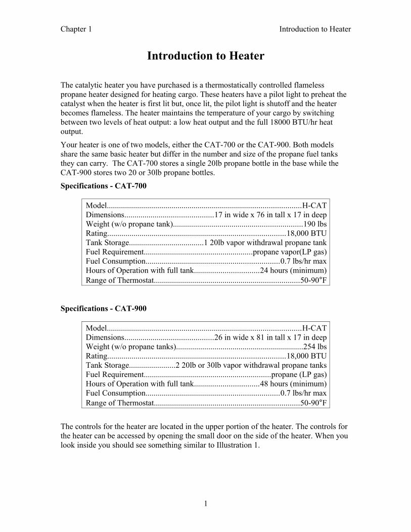
Specifications - CAT-700
Model................................................................................................H-CATDimensions............................................17 in wide x 76 in tall x 17 in deepWeight (w/o propane tank)................................................................190 lbsRating........................................................................................18,000 BTUTank Storage.....................................1 20lb vapor withdrawal propane tankFuel Requirement......................................................propane vapor(LP gas)Fuel Consumption..................................................................0.7 lbs/hr maxHours of Operation with full tank................................24 hours (minimum)Range of Thermostat........................................................................50-90F
Specifications - CAT-900
Model................................................................................................H-CATDimensions............................................26 in wide x 81 in tall x 17 in deepWeight (w/o propane tanks)...............................................................254 lbsRating........................................................................................18,000 BTUTank Storage.......................2 20lb or 30lb vapor withdrawal propane tanksFuel Requirement...............................................................propane (LP gas)Hours of Operation with full tank................................48 hours (minimum)Fuel Consumption..................................................................0.7 lbs/hr maxRange of Thermostat........................................................................50-90F
The controls for the heater are located in the upper portion of the heater. The controls for the heater can be accessed by opening the small door on the side of the heater. When you look inside you should see something similar to Illustration 1.
1
Chapter 1 Introduction to Heater
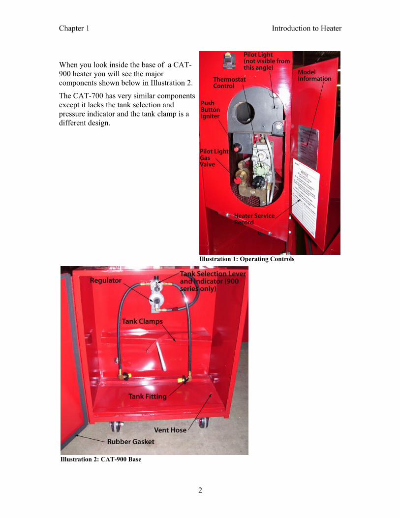
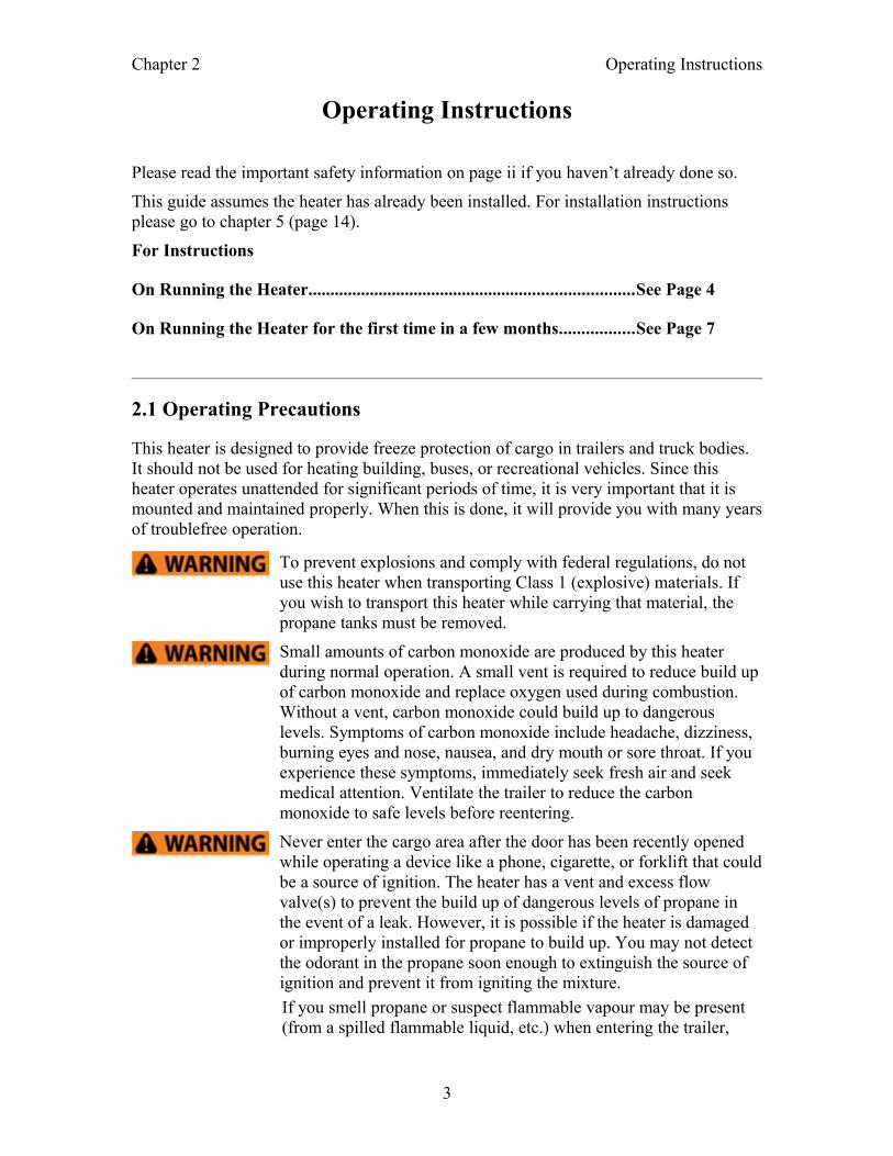
When you look inside the base of a CAT-900 heater you will see the major components shown below in Illustration 2.
The CAT-700 has very similar components except it lacks the tank selection and pressure indicator and the tank clamp is a different design.
2
Illustration 1: Operating Controls
Illustration 2: CAT-900 Base
Chapter 2 Operating Instructions
Operating Instructions
Please read the important safety information on page ii if you haven’t already done so.
This guide assumes the heater has already been installed. For installation instructions please go to chapter 5 (page 14).
For Instructions
On Running the Heater..........................................................................See Page 4
On Running the Heater for the first time in a few months.................See Page 7
2.1 Operating Precautions
This heater is designed to provide freeze protection of cargo in trailers and truck bodies. It should not be used for heating building, buses, or recreational vehicles. Since this heater operates unattended for significant periods of time, it is very important that it is mounted and maintained properly. When this is done, it will provide you with many years of troublefree operation.
To prevent explosions and comply with federal regulations, do not use this heater when transporting Class 1 (explosive) materials. If you wish to transport this heater while carrying that material, the propane tanks must be removed.
Small amounts of carbon monoxide are produced by this heater during normal operation. A small vent is required to reduce build up of carbon monoxide and replace oxygen used during combustion. Without a vent, carbon monoxide could build up to dangerous levels. Symptoms of carbon monoxide include headache, dizziness, burning eyes and nose, nausea, and dry mouth or sore throat. If you experience these symptoms, immediately seek fresh air and seek medical attention. Ventilate the trailer to reduce the carbon monoxide to safe levels before reentering.
Never enter the cargo area after the door has been recently opened while operating a device like a phone, cigarette, or forklift that could be a source of ignition. The heater has a vent and excess flow valve(s) to prevent the build up of dangerous levels of propane in the event of a leak. However, it is possible if the heater is damaged or improperly installed for propane to build up. You may not detect the odorant in the propane soon enough to extinguish the source of ignition and prevent it from igniting the mixture.
If you smell propane or suspect flammable vapour may be present (from a spilled flammable liquid, etc.) when entering the trailer,
3
Chapter 2 Operating Instructions
take immediate action. Follow your company's procedure if one is established. Otherwise:
• Do not do anything that could ignite the mixure including operating a electrical switch, disconnecting an extension cord, or using your phone. Do not light matches or any other source of flame.
• Get everyone away from the area immediately.
• Call your fuel supplier and/or the fire department
• Do not reenter the area until the trailer has been aired out and declared safe.
• Have a properly trained service person repair any leaks and bring the heater back into service.
Propane has a chemical added to give it a distinctive odor. If you are not familiar with that odor, please contact your local LP supplier. They can provide you with a scratch and sniff pamphlet. Use extra caution if you smoke or strong odors are present as this can make the odor difficult to notice. Like most other odors, extended exposure can reduce your sensitivity to the smell. Since LP gas is heavier than air, please remember that the odor will be stronger at lower levels.
2.2 Normal Operation
These instructions are for the day to day use of the heater. A shortened version of these instructions can be found on the side of the heater.
2.2.1 Lighting the Heater
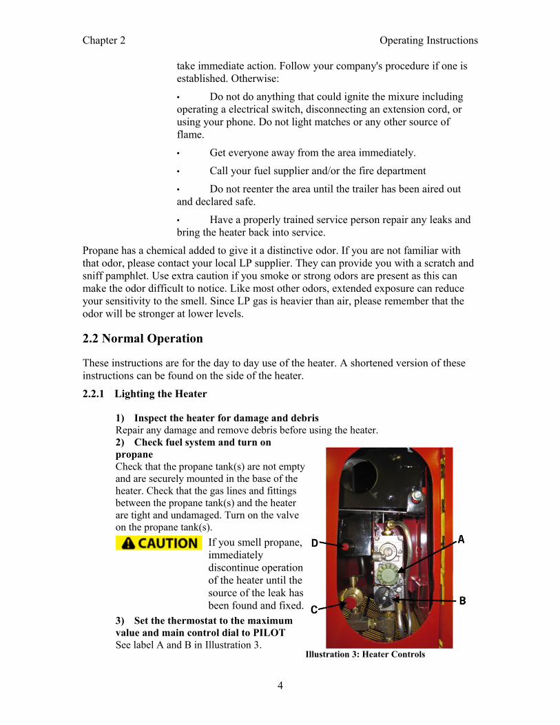
1) Inspect the heater for damage and debrisRepair any damage and remove debris before using the heater. 2) Check fuel system and turn on propane Check that the propane tank(s) are not empty and are securely mounted in the base of the heater. Check that the gas lines and fittings between the propane tank(s) and the heater are tight and undamaged. Turn on the valve on the propane tank(s).
If you smell propane, immediately discontinue operation of the heater until the source of the leak has been found and fixed.
3) Set the thermostat to the maximum value and main control dial to PILOTSee label A and B in Illustration 3.
4
Illustration 3: Heater Controls
Chapter 2 Operating Instructions
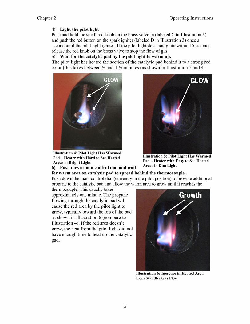
4) Light the pilot lightPush and hold the small red knob on the brass valve in (labeled C in Illustration 3) and push the red button on the spark igniter (labeled D in Illustration 3) once a second until the pilot light ignites. If the pilot light does not ignite within 15 seconds, release the red knob on the brass valve to stop the flow of gas. 5) Wait for the catalytic pad by the pilot light to warm up. The pilot light has heated the section of the catalytic pad behind it to a strong red color (this takes between ½ and 1 ½ minutes) as shown in Illustration 5 and 4.
6) Push down main control dial and wait for warm area on catalytic pad to spread behind the thermocouple. Push down the main control dial (currently in the pilot position) to provide additional propane to the catalytic pad and allow the warm area to grow until it reaches the thermocouple. This usually takes approximately one minute. The propane flowing through the catalytic pad will cause the red area by the pilot light to grow, typically toward the top of the pad as shown in Illustration 6 (compare to Illustration 4). If the red area doesn’t grow, the heat from the pilot light did not have enough time to heat up the catalytic pad.
5
Illustration 4: Pilot Light Has Warmed Pad – Heater with Hard to See Heated Areas in Bright Light
Illustration 5: Pilot Light Has Warmed Pad – Heater with Easy to See Heated Areas in Dim Light
Illustration 6: Increase in Heated Area from Standby Gas Flow
Chapter 2 Operating Instructions
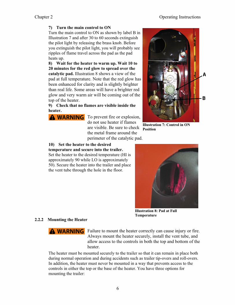
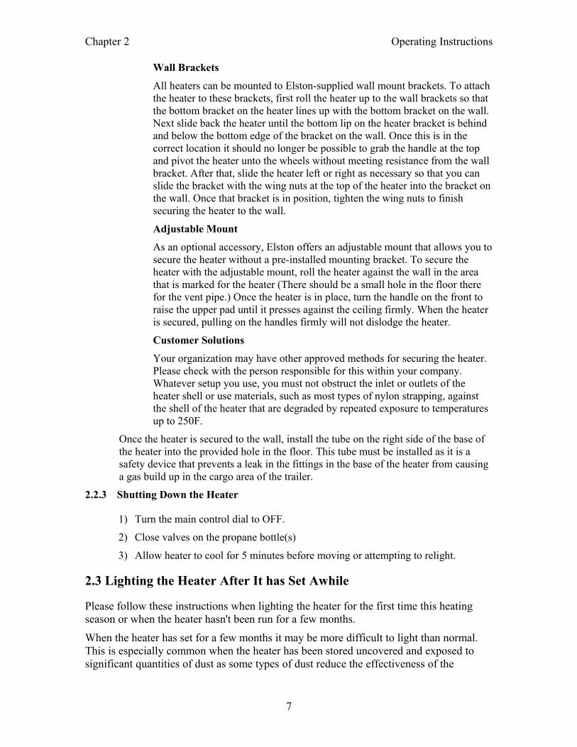
7) Turn the main control to ON Turn the main control to ON as shown by label B in Illustration 7 and after 30 to 60 seconds extinguish the pilot light by releasing the brass knob. Before you extinguish the pilot light, you will probably see ripples of flame travel across the pad as the pad heats up.8) Wait for the heater to warm up. Wait 10 to 20 minutes for the red glow to spread over the catalytic pad. Illustration 8 shows a view of the pad at full temperature. Note that the red glow has been enhanced for clarity and is slightly brighter than real life. Some areas will have a brighter red glow and very warm air will be coming out of the top of the heater.9) Check that no flames are visible inside the heater.
To prevent fire or explosion, do not use heater if flames are visible. Be sure to check the metal frame around the perimeter of the catalytic pad.
10) Set the heater to the desired temperature and secure into the trailer. Set the heater to the desired temperature (HI is approximately 90 while LO is approximately 50). Secure the heater into the trailer and place the vent tube through the hole in the floor.
2.2.2 Mounting the Heater
Failure to mount the heater correctly can cause injury or fire. Always mount the heater securely, install the vent tube, and allow access to the controls in both the top and bottom of the heater.
The heater must be mounted securely to the trailer so that it can remain in place both during normal operation and during accidents such as trailer tip-overs and roll-overs. In addition, the heater must never be mounted in a way that prevents access to the controls in either the top or the base of the heater. You have three options for mounting the trailer:
6
Illustration 7: Control in ON Position
Illustration 8: Pad at Full Temperature
Chapter 2 Operating Instructions
Wall Brackets
All heaters can be mounted to Elston-supplied wall mount brackets. To attach the heater to these brackets, first roll the heater up to the wall brackets so that the bottom bracket on the heater lines up with the bottom bracket on the wall. Next slide back the heater until the bottom lip on the heater bracket is behind and below the bottom edge of the bracket on the wall. Once this is in the correct location it should no longer be possible to grab the handle at the top and pivot the heater unto the wheels without meeting resistance from the wall bracket. After that, slide the heater left or right as necessary so that you can slide the bracket with the wing nuts at the top of the heater into the bracket on the wall. Once that bracket is in position, tighten the wing nuts to finish securing the heater to the wall.
Adjustable Mount
As an optional accessory, Elston offers an adjustable mount that allows you to secure the heater without a pre-installed mounting bracket. To secure the heater with the adjustable mount, roll the heater against the wall in the area that is marked for the heater (There should be a small hole in the floor there for the vent pipe.) Once the heater is in place, turn the handle on the front to raise the upper pad until it presses against the ceiling firmly. When the heater is secured, pulling on the handles firmly will not dislodge the heater.
Customer Solutions
Your organization may have other approved methods for securing the heater. Please check with the person responsible for this within your company. Whatever setup you use, you must not obstruct the inlet or outlets of the heater shell or use materials, such as most types of nylon strapping, against the shell of the heater that are degraded by repeated exposure to temperatures up to 250F.
Once the heater is secured to the wall, install the tube on the right side of the base of the heater into the provided hole in the floor. This tube must be installed as it is a safety device that prevents a leak in the fittings in the base of the heater from causing a gas build up in the cargo area of the trailer.
2.2.3 Shutting Down the Heater
1) Turn the main control dial to OFF.
2) Close valves on the propane bottle(s)
3) Allow heater to cool for 5 minutes before moving or attempting to relight.
2.3 Lighting the Heater After It has Set Awhile
Please follow these instructions when lighting the heater for the first time this heating season or when the heater hasn't been run for a few months.
When the heater has set for a few months it may be more difficult to light than normal. This is especially common when the heater has been stored uncovered and exposed to significant quantities of dust as some types of dust reduce the effectiveness of the
7
Chapter 2 Operating Instructions
catalytic pad. This effect is generally temporary and will largely disappear after the heater has ran at full power for an hour.
1) Inspect the heater for damage and debrisCheck the propane system for damage including cracked hoses, worn o-rings in the pilot light valve and tank fittings, and damaged tubing and replace any damaged components. Check inside the heater for debris especially around the catalytic pad and remove all debris present.2) Check fuel system and turn on propaneCheck that the propane tank(s) are not empty and are securely mounted in the base of the heater. Check that the fittings between the propane tank(s) and the heater are tight and undamaged. Turn on the valve on the propane tank(s).
If you smell propane, immediately discontinue operation of the heater until the source of the leak has been found and fixed.
3) Set the thermostat to the maximum value and main control dial to PILOT 4) Light the pilot light Push and hold the small red knob on the brass valve in and push the red button on the spark igniter once a second until the pilot light ignites. If the pilot light does not ignite within 15 seconds, release the red knob on the brass valve to stop the flow of gas. 5) Wait for the catalytic pad by the pilot light to warm up. Wait approximately one minute until a dull red glow appears on the catalytic pad near the pilot flame. See Illustration 4 and 5 on page 5 for example view of the pad.6) Push down main control dial and wait for warm area on catalytic pad to spread behind the thermocouple. Push down the main control dial (currently in the pilot position) to provide additional propane to the catalytic pad and allow the warm area to grow until it reaches the thermocouple. After approximately one minute, the red area by the pilot light should start to grow, typically toward the top of the pad as shown in Illustration 6 (compare to Illustration 5).7) Turn the main control to ON Turn the main control to ON and after 30 to 60 seconds extinguish the pilot light by releasing the brass knob. Before you extinguish the pilot light, you will probably see ripples of flame travel across the pad as the pad heats up. 8) Wait for the heater to warm up.Wait 10 to 20 minutes for the red glow to spread over the catalytic pad.9) Check that no flames are visible inside the heater
To prevent fire or explosion, do not use heater if any flames are visible. Be sure to check the metal frame around the perimeter of the catalytic pad.
10) Set the heater to the desired temperature and secure into the trailer. Set the heater to the desired temperature (HI is approximately 90 while LO is approximately 50). Secure the heater into the trailer and place the vent tube through the hole in the floor.
8
Chapter 3 Service Instructions
Service Instructions
3.1 Every Time You Walk By the Heater
Check the exterior of the heater and the exterior hoses for damage
Check that the doors on the base of the heater and the side of the heater are closed
3.2 Every Time the Trailer is Loaded and Unloaded
Check the exterior of the heater for damage and the openings of the heater for obstructions.
Check that the heater is securely attached to the wall of the trailer and the vent tube is installed through a hole in the floor.
3.3 Annually Before the Start of the Winter Season
Carefully inspect the propane tank, regulator, and fuel lines. Replace any damaged or deteriorated hoses, worn o-rings, and tighten any loose fittings. Check the propane system for leaks.
Replace any labels that are missing or can no longer be read.
Check inside the heater for debris especially around the catalytic pad and remove all debris present.
Start up and run the heater to check that everything is in working order.
9
Chapter 4 Troubleshooting
Troubleshooting
If this guide doesn’t fix your problem please contact the company where you purchased the heater. If you are unable to contact them or you need additional help, please contact Elston Manufacturing at 1-800-845-1385.
For your safety, the propane should always be turned off when troubleshooting this product except when required to test the function of the heater.
What is wrong with the heater?
A. Pilot light doesn't light
B. Pilot light does not create a hot spot on the catalytic pad
C. Pad never gets hot when lighting heater
D. Pad takes a long time to get to full temperature
E. Heater goes out after running at least 30 minutes but before the tank is empty
F. Flames are visible after the pilot light is extinguished
Problem A: Pilot Light Doesn't Light
Cause: Propane tank is empty
Makes sure the propane tank is not empty. If you have a CAT-900, check that the tank selection lever is pointing toward a non-empty tank. When the lever is pointing toward a tank and the valve for that tank is on, you should see green in the window on the regulator when the selected tank contains propane.
Cause: Excess flow valve was triggered
If the valve on the tank is opened quickly, the initial pulse of gas into the gas lines for the heater may trigger the excess flow valve built into the heater which restricts gas flow to a very low value. Close the tank valve(s) and slowly open them to reset the excess flow valve.
Cause: Problem with push button sparker
Check that the wire on the back of the push button sparker is attached and the spark is not jumping to the frame of the catalytic pad. If the spark is jumping to the frame of the catalytic pad, loosen the two screws attaching the pilot light assembly and slight the assembly slightly away from the catalytic pad while keeping it at the same angle to the pad and retighten the screws.
Cause: Pilot light orifices are plugged
10
Chapter 4 Troubleshooting
The gas for the pilot light travels through 2 sets of orifices, either of which can block the flow of gas. The first orifice is in the pilot light valve block and the second is in the pilot light assembly. It is also possible that some debris, such as a spider web or dead bug, is in the channel in the pilot light and blocking the flow of gas toward the spark.
Problem B: Pilot Light Does Not Create a Hot Spot on the Catalytic Pad
Cause: Excess flow valve was triggered
If the valve on the tank is opened quickly, the initial pulse of gas into the gas lines for the heater may trigger the excess flow valve built into the heater. Close the tank valve(s) and slowly open them to reset the excess flow valve.
Cause: Pilot light orifices are partially plugged
The gas for the pilot light travels through 2 sets of orifices, either of which can block the flow of gas. The first orifice is in the pilot light valve block and the second is in the pilot light assembly. It is also possible that some debris, such as a spider web or a dead bug, is in the channel in the pilot light and blocking the flow of gas toward the catalytic pad.
Cause: Position of the pilot light assembly is incorrect
The large flame of the pilot light should touch or nearly touch the pad near the edge of the thermocouple plate. The pilot light can hit the plate but at least half the flame must touch the pad. If more than this portion of the pilot light hits the thermocouple plate, loosen the two screw attaching the pilot light assembly and move it to the correct location. When retightening the assembly into place, make sure that the sparker is more than 1/4” from the frame of the catalytic pad to prevent the spark from jumping to an incorrect location and preventing you from lighting the pilot light.
Problem C: Catalytic Pad Never Gets Hot When Lighting Heater
Cause: Temperature is not low enough for thermostat to turn heater completely on
If the temperature where you are lighting the heater is above 60 F, the thermostat may not turn on the full flow of gas even when the thermostat dial is set to HI. Move the heater to a cooler location or cool the thermostat probe with an ice cube and retry the lighting process.
Cause: Catalytic pad was not sufficiently prewarmed earlier in the lighting process
The pilot light must get at least a small area of the catalyst warm enough to activate the catalyst and get the thermocouple warm enough to allow gas to flow through the control before the pilot light is extinguished. If either (or both) of these doesn't happen, the safety system on the heater will shut it down. If you haven't already done so please try lighting the heater following the instructions found in this manual.
When the extended lighting instructions don't work, this problem is typically caused by one of four reasons:
11
Chapter 4 Troubleshooting
1. The pilot light was not left on long enoughMake sure that you leave the pilot light on for at least 60 seconds between each step to allow the heat to penetrate into the pad and spread a little bit.
2. The thermocouple is out of positionIf the thermocouple is more than a ¼” from the catalytic pad or tilted at an angle (more than a few degrees), the heat from the pad may fail to get the thermocouple hot enough to allow gas to flow through the control. If the thermocouple is out of position, remove the bottom grill on the heater and loosen the screw holding the thermocouple and adjust the thermocouple so the plate is parallel to the pad and 1/8” from the pad.
3. The pilot light is too smallRefer to the tips in problem B above for recommendations.
4. The thermocouple has failedIf none of the above recommendations help and the pad remains glowing by the pilot light when the control is pushed down in the PILOT position and the pilot light is temporarily extinguished, the thermocouple has failed and needs to be replaced.
Cause: Gas supply problems
If the gas supply to the heater is partially restricted the heater will only be able to get enough propane for the pilot light. Check that the selection lever is pointing toward a full tank and tank valve is open at least a full turn. If you have the tools, check that the heater is receiving 11” water column of propane vapor throughout the lighting process.
Problem D: Catalytic Pad Takes a Long Time to Get to Full Temperature
Cause: Catalytic pad was not sufficiently prewarmed earlier in the lighting process
If the area of the catalyst warm enough to activate the catalyst is too small it will take a long time for the pad to get to full temperature. If you haven't already done so please try lighting the heater following the instructions found in this manual.
When the extended lighting instructions don't work, this problem is typically caused by one of three reasons:
1. The pilot light was not left on long enoughMake sure that you leave the pilot light on for at least 60 seconds between each step to allow the heat to penetrate into the pad and spread a little bit.
2. The pilot light is out of positionIf the pilot light hits the plate on the thermocouple instead of hitting the catalytic pad, the pad will barely heat up. Adjust the postion of the pilot light assembly and/or the thermocouple so that the large flame of the pilot light touches or nearly touches the pad near the edge of the thermocouple plate.
3. The pilot light is too smallRefer to the tips in problem B above for recommendations.
12
Chapter 4 Troubleshooting
Cause: Catalytic pad is worn out
If the catalytic pad is covered in too much dust the propane is unable to effectively interact with the catalyst. Gently blow any dust off of the pad being careful not to damage the pad. If that doesn't work, the pad may be worn out and need to be replaced. It takes a few years for a pad to wear out and the typical life span is around ten years.
Problem E: Heater Goes Out After Running at Least 30 Minutes
Cause: Catalytic pad is worn out
If the catalytic pad is covered in too much dust the propane is unable to effectively interact with the catalyst. Gently blow any dust off of the pad being careful not to damage the pad. If that doesn't work, the pad may be worn out and unable to remain hot enough when the heater is on standby. A worn out pad will be nearly white and needs to be replaced.
Cause: The thermocouple is out of position
If the thermocouple is more than a 1/8” from the catalytic pad or tilted at an angle (more than a few degrees), the thermocouple may not remain hot enough when the heater is on standby to allow gas to flow through the control. If the thermocouple is out of position, remove the bottom grill on the heater and loosen the screw holding the thermocouple and adjust the thermocouple so the plate is parallel to the pad and 1/8” from the pad.
Problem F: Flames are Visible after Pilot Light is Extinguished
Cause: Damage to catalytic pad or sealing cement
Use high temperature furnace cement to repair the damaged or missing sealant. If cement has been lost from around a screw, retighten the screw before applying new cement.
13
Chapter 5 Installation
Installation
Improper installation of this heater creates a substantial safety hazard including the risk of property damage, fire, death.
Compliance with local regulation is the responsibility of the installer. Current regulations in your area may require that the installer of this heater or, more likely, that the installer of the propane system fueling this heater meet certain requirements and/or that the completed installation be inspected. If you are unsure what is required, please refer to the current regulations in your area or speak with the authority having jurisdiction before beginning installation.
5.1 Overview
These purpose of these instructions is to aid you in installing a fully functional heater that is safe and secure under both normal condition and, as much as possible, during an accident. However these instructions are not a substitute for personal knowledge and experience with installing propane and/or electrical systems. Please do not install those areas of the heater unless you have personal knowledge and experience in these areas.
These instructions were written with the latest standards for the US in mind and are intended to guide you in an installation that meets these standards. At the time of writing, the latest standard was the 2008 edition of NFPA 58, the Liquefied Petroleum Gas Code and part 393.77 of the Federal Motor Carrier Safety Administration rules. However, if the regulations that apply in your area conflict with these installation instructions the regulations should always be followed instead.
Setup for these heaters is simple as they are designed to roll on and off cargo trailers and van bodies to provide heat as needed but does require some setup work on the trailers you plan to use the heater in. The exact setup depends on if you are using the standard mounting brackets or the optional adjustable mount.
5.2 Unpacking the Heater and Gathering Supplies
Parts Needed for Installation shipped with Heater:
Roll on Heater
Lower wall mount bracket
Upper wall mount bracket
Additional parts required:
12 to 16 screws or bolts appropriate for securing 1/8” thick steel to the trailer wall per set of mounting brackets
Additional lower and upper wall brackets (optional)
14
Chapter 5 Installation
Tape or paint for marking out the boundaries of the heater to ensure space remains for heater after cargo is loaded (recommended)
5.3 Mounting
Failure to mount the brackets for the heater securely or drill the hole for the vent tube will cause serious safety hazards when the heater is operated.
Every trailer or truck body where you plan to use the heater will need to be prepared for use.
The primary consideration for the placement of the heater is a position against a wall of the trailer that can easily be left open for the heater after cargo is loaded.
Setup for Standard Mounting Brackets
Install the lower bracket on the wall with the base of the bracket against the floor. Attach the bracket to supports in the wall for maximum strength in a position where the hole for the vent tube will not have to be drilled through one of the supports for the trailer floor. Make sure the bracket is firmed attached to wall so that you would reasonable expect the bracket to bend before pulling the screw or bolts out of the wall.
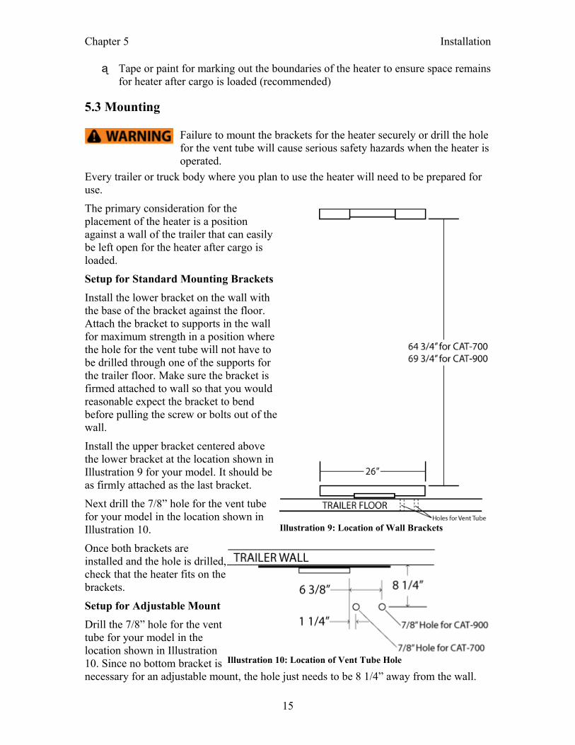
Install the upper bracket centered above the lower bracket at the location shown in Illustration 9 for your model. It should be as firmly attached as the last bracket.
Next drill the 7/8” hole for the vent tube for your model in the location shown in Illustration 10.
Once both brackets are installed and the hole is drilled, check that the heater fits on the brackets.
Setup for Adjustable Mount
Drill the 7/8” hole for the vent tube for your model in the location shown in Illustration 10. Since no bottom bracket is necessary for an adjustable mount, the hole just needs to be 8 1/4” away from the wall.
15
Illustration 9: Location of Wall Brackets
Illustration 10: Location of Vent Tube Hole
Chapter 5 Installation
5.4 Final details
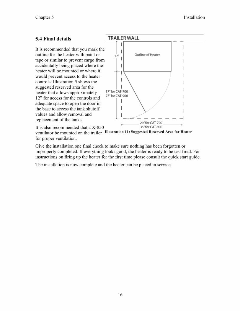
It is recommended that you mark the outline for the heater with paint or tape or similar to prevent cargo from accidentally being placed where the heater will be mounted or where it would prevent access to the heater controls. Illustration 5 shows the suggested reserved area for the heater that allows approximately 12” for access for the controls and adequate space to open the door in the base to access the tank shutoff values and allow removal and replacement of the tanks.
It is also recommended that a X-850 ventilator be mounted on the trailer for proper ventilation.
Give the installation one final check to make sure nothing has been forgotten or improperly completed. If everything looks good, the heater is ready to be test fired. For instructions on firing up the heater for the first time please consult the quick start guide.
The installation is now complete and the heater can be placed in service.
16
Illustration 11: Suggested Reserved Area for Heater
Chapter 6 Parts List for Catalytic Heaters
Parts List for Catalytic Heaters
CAT-700...........................................................................................................................A5Complete Heater
CAT-900...........................................................................................................................A6Complete Heater
H700/900-CH....................................................................................................................A9Basic Catalytic Heater (top portion of heater)
H700/900-CIA................................................................................................................A10Inner Assembly for Basic Catalytic Heater
H10-715..........................................................................................................................A11Catalytic Pad Assembly
H700/900-CCP...............................................................................................................A12Control Panel Assembly for Basic Catalytic Heater
H700-BC.........................................................................................................................A13Bottle Carrier for CAT-700
H900-BC.........................................................................................................................A14Bottle Carrier for CAT-900
H700-RA.........................................................................................................................A15Regulator Assembly for CAT-700
H900-RA ........................................................................................................................A15Regulator Assembly for CAT-900
17

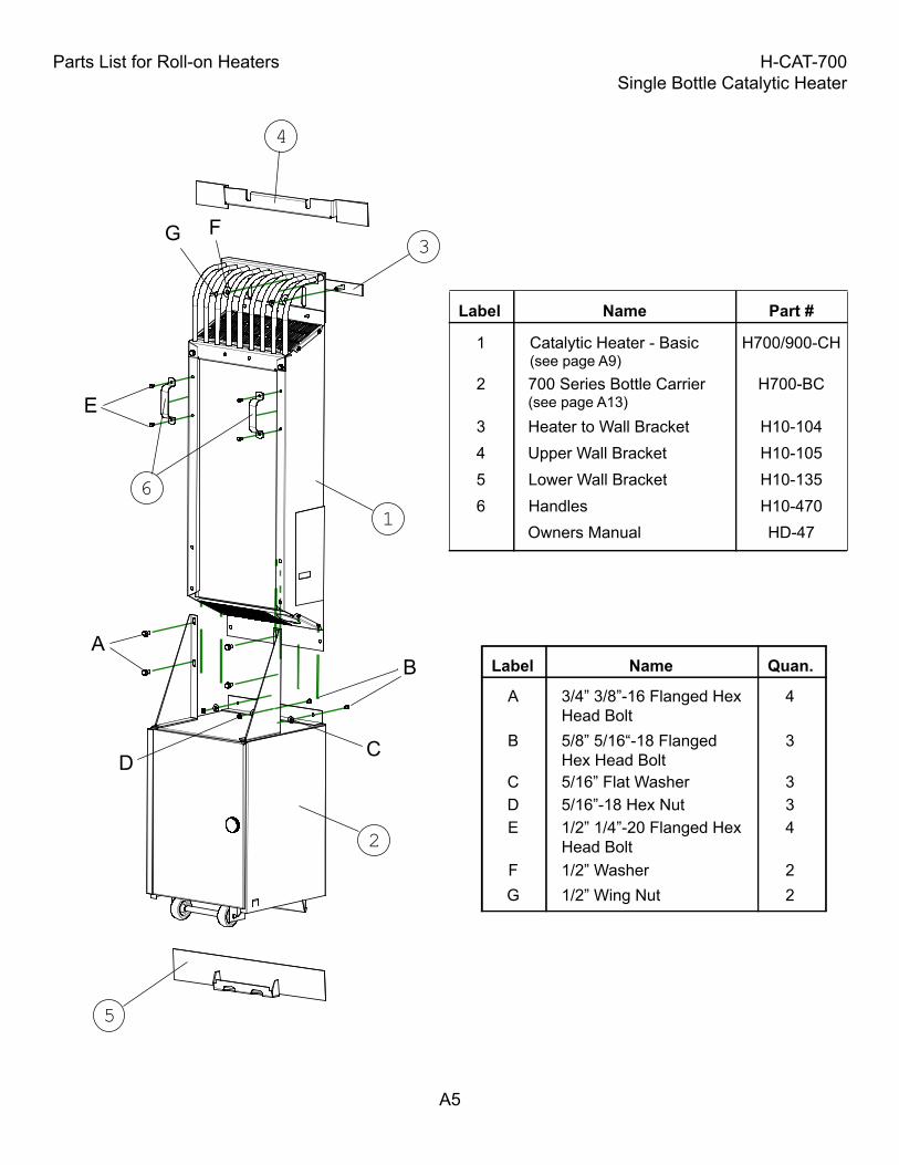
Parts List for Roll-on Heaters H-CAT-700Single Bottle Catalytic Heater
A5
Label Name Part #
1 Catalytic Heater - Basic(see page A9)
H700/900-CH
2 700 Series Bottle Carrier(see page A13)
H700-BC
3 Heater to Wall Bracket H10-1044 Upper Wall Bracket H10-1055 Lower Wall Bracket H10-135
Label Name Quan.
A 3/4” 3/8”-16 Flanged Hex Head Bolt
4
B 5/8” 5/16“-18 Flanged Hex Head Bolt
3
E 1/2” 1/4”-20 Flanged HexHead Bolt
4
F 1/2” Washer 2G 1/2” Wing Nut 2
Owners Manual HD-47
AB
E
FG
6 Handles H10-470
C 5/16” Flat Washer 3D 5/16”-18 Hex Nut 3
1
2
3
5
4
6
CD
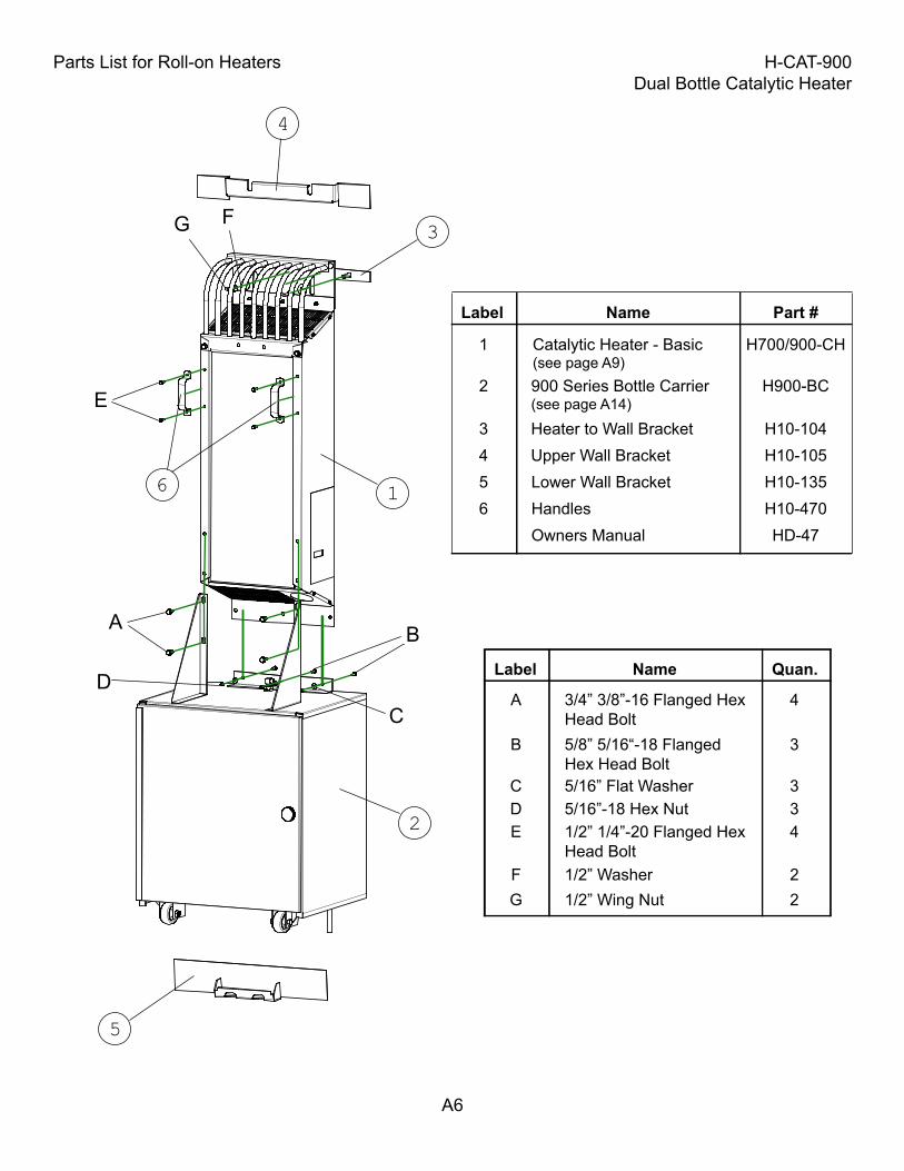
Parts List for Roll-on Heaters H-CAT-900Dual Bottle Catalytic Heater
A6
Label Name Part #
1 Catalytic Heater - Basic(see page A9)
H700/900-CH
2 900 Series Bottle Carrier(see page A14)
H900-BC
3 Heater to Wall Bracket H10-1044 Upper Wall Bracket H10-1055 Lower Wall Bracket H10-135
Label Name Quan.
A 3/4” 3/8”-16 Flanged Hex Head Bolt
4
B 5/8” 5/16“-18 Flanged Hex Head Bolt
3
E 1/2” 1/4”-20 Flanged HexHead Bolt
4
F 1/2” Washer 2G 1/2” Wing Nut 2
A B
E
FG
6 Handles H10-470Owners Manual HD-47
C 5/16” Flat Washer 3D 5/16”-18 Hex Nut 3
1
2
3
5
4
6
CD
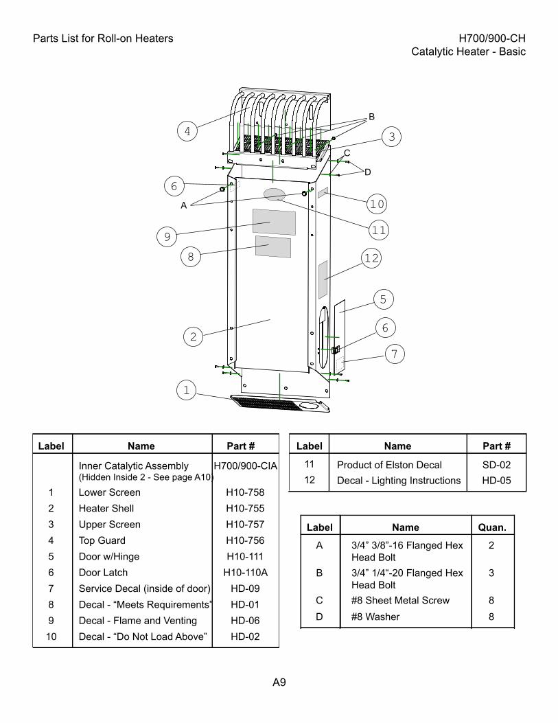
Parts List for Roll-on Heaters H700/900-CHCatalytic Heater - Basic
A9
Label Name Part #
Inner Catalytic Assembly (Hidden Inside 2 - See page A10)
H700/900-CIA
1 Lower Screen H10-7582 Heater Shell H10-7553 Upper Screen H10-7574 Top Guard H10-756
Label Name Quan.
A 3/4” 3/8”-16 Flanged Hex Head Bolt
2
B 3/4” 1/4“-20 Flanged HexHead Bolt
3
C #8 Sheet Metal Screw 8D #8 Washer 8
A
B
C
5 Door w/Hinge H10-111
D
6 Door Latch H10-110A7 Service Decal (inside of door) HD-098 Decal - “Meets Requirements” HD-019 Decal - Flame and Venting HD-06
10 Decal - “Do Not Load Above” HD-02
12 Decal - Lighting Instructions HD-0511 Product of Elston Decal SD-02
1
2
4 3
5
6
7
8
610
12
11
Label Name Part #
9
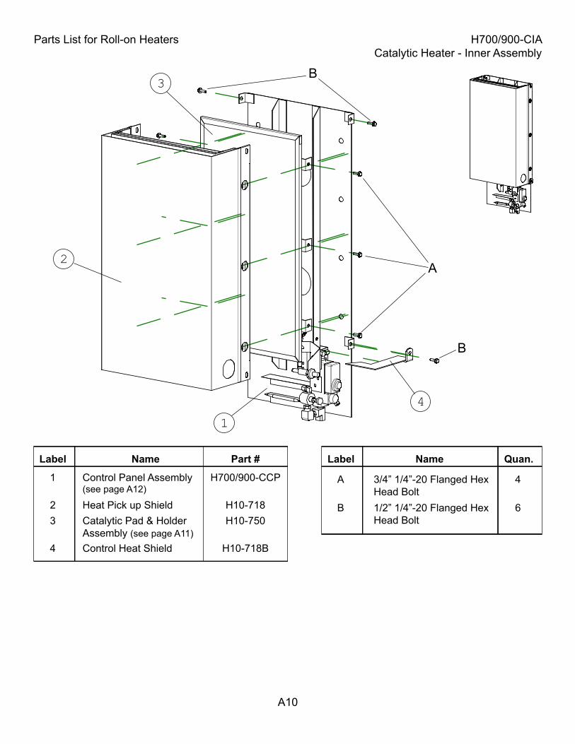
Parts List for Roll-on Heaters H700/900-CIACatalytic Heater - Inner Assembly
A10
Label Name Part #
2 Heat Pick up Shield H10-7183 Catalytic Pad & Holder
Assembly (see page A11)H10-750
1 Control Panel Assembly(see page A12)
H700/900-CCP
4 Control Heat Shield H10-718B
Label Name Quan.
A 3/4” 1/4”-20 Flanged Hex Head Bolt
4
B 1/2” 1/4”-20 Flanged Hex Head Bolt
6
A
B
2
1
3
4
B
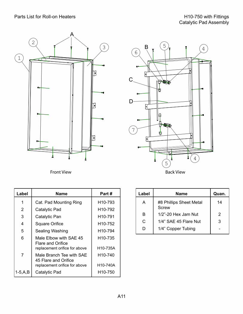
Parts List for Roll-on Heaters H10-750 with FittingsCatalytic Pad Assembly
A11
Label Name Part #
1 Cat. Pad Mounting Ring H10-7932 Catalytic Pad H10-792
1-5,A,B Catalytic Pad H10-750
3 Catalytic Pan H10-7914 Square Orifice H10-7525 Sealing Washing H10-794
Label Name Quan.
A #8 Phillips Sheet MetalScrew
14
B 1/2”-20 Hex Jam Nut 2C 1/4” SAE 45 Flare Nut 3D 1/4” Copper Tubing -
C
D
6 Male Elbow with SAE 45 Flare and Orificereplacement orifice for above
H10-735
H10-735A
B
7 Male Branch Tee with SAE 45 Flare and Orificereplacement orifice for above
H10-740
H10-740A
1
5 4
Front View Back View
2
63
7
54
A
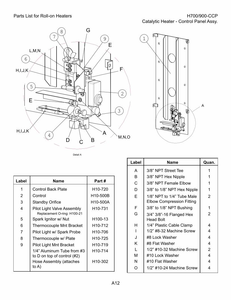
Parts List for Roll-on Heaters H700/900-CCPCatalytic Heater - Control Panel Assy.
A12
Label Name Part #
1 Control Back Plate H10-720
4 Pilot Light Valve Assembly H10-731
7 Pilot Light w/ Spark Probe H10-706
5 Spark Ignitor w/ Nut H100-13
2 Control H10-500B
Label Name Quan.
A 3/8” NPT Street Tee 1B 3/8” NPT Hex Nipple 1C 3/8” NPT Female Elbow 1D 3/8” to 1/8” NPT Hex Nipple 1E 1/8” NPT to 1/4” Tube Male
Elbow Compression Fitting2
F
A
C
L,M,N
3 Standby Orifice H10-500A
8 Thermocouple w/ Plate H10-725
6 Thermocouple Mnt Bracket H10-712
1/4” Aluminum Tube from #3to D on top of control (#2)
H10-714
Hose Assembly (attachesto A)
H10-302
E
G
9 Pilot Light Mnt Bracket H10-719
F 3/8” to 1/8” NPT Bushing 1G 23/4” 3/8”-16 Flanged Hex
Head BoltH 1/4” Plastic Cable Clamp 4I 1/2” #8-32 Machine Screw 4J #8 Lock Washer 4K #8 Flat Washer 4L 1/2” #10-32 Machine Screw 2M #10 Lock Washer 4N #10 Flat Washer 4O 1/2” #10-24 Machine Screw 4
Replacement O-ring: H100-21
1
4
2
3
78
5
D
E
H,I,J,K
M,N,OH,I,J,K
9
6
B
A
Detail A
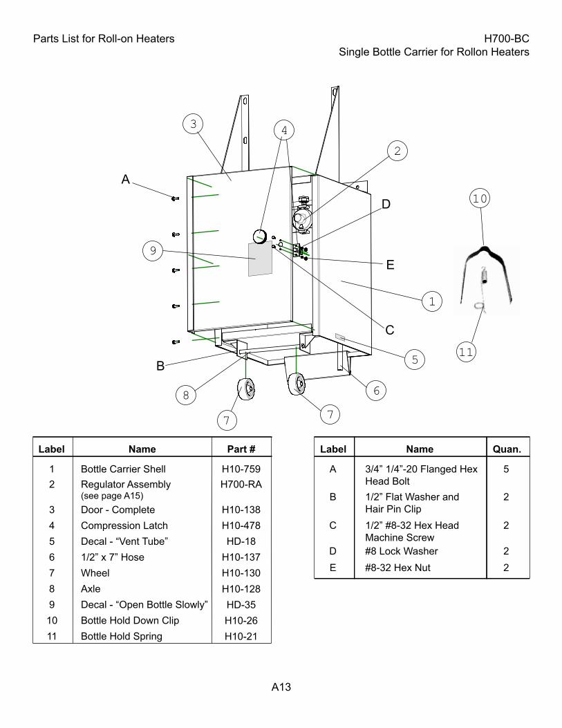
Parts List for Roll-on Heaters H700-BCSingle Bottle Carrier for Rollon Heaters
A13
Label Name Part #
1 Bottle Carrier Shell H10-7592 Regulator Assembly
(see page A15)H700-RA
3 Door - Complete H10-138
6 1/2” x 7” Hose H10-1377 Wheel H10-130
Label Name Quan.
A 3/4” 1/4”-20 Flanged Hex Head Bolt
5
B 1/2” Flat Washer andHair Pin Clip
2
C 1/2” #8-32 Hex HeadMachine Screw
2
D #8 Lock Washer 2E #8-32 Hex Nut 2
A
B
C
D
E
10 Bottle Hold Down Clip H10-269 Decal - “Open Bottle Slowly” HD-35
5 Decal - “Vent Tube” HD-184 Compression Latch H10-478
8 Axle H10-128
11 Bottle Hold Spring H10-21
9
2
3
7
8
7
4
6
5
1
10
11
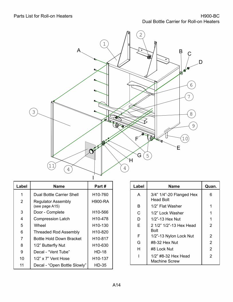
Parts List for Roll-on Heaters H900-BCDual Bottle Carrier for Roll-on Heaters
A14
Label Name Part #
1 Dual Bottle Carrier Shell H10-7602 Regulator Assembly
(see page A15)H900-RA
3 Door - Complete H10-5664 Compression Latch H10-4785 Wheel H10-130
Label Name Quan.
A 3/4” 1/4”-20 Flanged Hex Head Bolt
6
B 1/2” Flat Washer 1C 1/2” Lock Washer 1
E 2 1/2” 1/2”-13 Hex HeadBolt
2
I 1/2” #8-32 Hex Head Machine Screw
2
A B
F
7 Bottle Hold Down Bracket H10-8176 Threaded Rod Assembly H10-820
8 1/2” Butterfly Nut H10-6309 Decal - “Vent Tube” HD-18
11 Decal - “Open Bottle Slowly” HD-3510 1/2” x 7” Vent Hose H10-137
F 1/2”-13 Nylon Lock Nut 2
D 1/2”-13 Hex Nut 1
G #8-32 Hex Nut 2H #8 Lock Nut 2
1
2
3
5
9
7
8
6
44
10
11
CD
EG
H
I
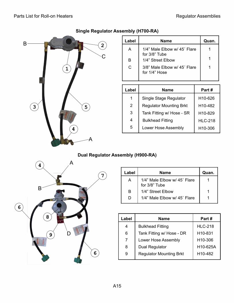
Parts List for Roll-on Heaters Regulator Assemblies
A15
Label Name Part #
1 Single Stage Regulator H10-626
2 Regulator Mounting Brkt H10-482
Single Regulator Assembly (H700-RA)
Dual Regulator Assembly (H900-RA)
3 Tank Fitting w/ Hose - SR H10-829
4 Bulkhead Fitting HLC-218
4 Bulkhead Fitting HLC-218
Label Name Part #
6 Tank Fitting w/ Hose - DR H10-8317 Lower Hose Assembly H10-3068 Dual Regulator H10-625A9 Regulator Mounting Brkt H10-482
Label Name Quan.
Label Name Quan.
A 1/4” Male Elbow w/ 45˚ Flarefor 3/8” Tube
1
B 1/4” Street Elbow 1
A 1/4” Male Elbow w/ 45˚ Flarefor 3/8” Tube
1
B 1/4” Street Elbow 1D 1/4” Male Elbow w/ 45˚ Flare 1
5 Lower Hose Assembly H10-306
C 3/8” Male Elbow w/ 45˚ Flarefor 1/4” Hose
1
8
B
7
4
6
6
A
9 D
1
4
3 5
2
A
B
C

LIMITED WARRANTY TERMSElston Manufacturing, Inc. offers a one (1) year, non-transferable, Limited Warranty against specified defects as set forth below for Elston Manufacturing, Inc. product lines from the date of purchase through proof of purchase by providing original receipt.This Limited Warranty specifically excludes normal wear and tear of products and is provided solely under the conditions that the product has been properly installed, operated and maintained in accordance with all applicable instructions. Proper installation instructions, or operating manuals, are provided with each product and operating condition. Travel, diagnostic cost, labor, transportation and any and all such costs related to reparing a defective product will be the responsibility of the owner. This warranty is extended only to the original owner of any equipment, the end user.Elston Manufacturing, Inc.'s sole obligation under this Limited Warranty is to, in its sole and absolute discretion, either repair, modify, or replace (i.e. correct), Elston Manufacturing, Inc.'s products subject to this Limited Warranty. The allegedly defective products must be returned to Elston Manufacturing Inc. or an authorized service center freight paid by buyer. After confirmation by Elston Manufacturing, Inc. that a defect does exist in the product that is covered under this Limited Warranty then Elston Manufacturing, Inc. shall, in its sole and absolute discretion, either repair, modify or replace the product(s) and return the product(s) to the owner freight paid by Elston Manufacturing, Inc.Elston Manufacturing, Inc. products received by Elston Manufacturing, Inc. within one (1) year from the original sale date to customer and found to be defective as referenced above will be corrected as referenced in the previous paragraph at no charge for parts (provided by original factory) or labor but will include freight paid by buyer. Failure to use original factory parts voids this warranty. Elston Manufacturing, Inc. products received by Elston Manufacturing, Inc. after one (1) year from original shipment date to customer will be corrected as foresaid for a charge of the then-current sale price of parts and labor with freight paid by buyer. Exception: Any parts to be found defective at any time that come under a recall status from providing manufacturer, will be covered under the terms and conditions of the recall status provided by manufacturer.THIS LIMITED WARRANTY BY ELSTON MANUFACTURING, INC. IS IN LIEU OF ANY AND ALL OTHER WARRANTIES, EXPRESSED OR IMPLIED, INCLUDING WITHOUT LIMITATION TOTHE IMPLIED WARRANTIES OF MERCHANTABILITY AND FITNESS FOR A PARTICULAR PURPOSE. NO ONE IS AUTHORIZED BY ELSTON MANUFACTURING, INC. TO EXTEND OR ALTER THE TERMS OF THIS LIMITED WARRANTY. ELSTON MANUFACTURING, INC. ASSUMES NO LIABILITY FOR LOSS OF USE OR ANY DIRECT, INDIRECT, INCIDENTAL, SPECIAL, CONSEQUENTIAL OR OTHER DAMAGES OF ANY KIND IN RESPECT TO THE USE OF THE ELSTON MANUFACTURING, INC EQUIPMENT. Accessory items furnished by Elston Manufacturing, Inc. are covered by a Limited Warranty for a period of one (1) year from date of original sale, subject to the conditions, limitations, and disclaimers stated above, for replacement of defective materials, provided such items are returned freight paid by buyer to Elston Manufacturing, Inc. and are determined by Elston Manufacturing, Inc. to be defective in its sole and absolute discretion.This Limited Warranty shall not apply to any piece of equipment, parts or accessories repaired by anyone other than Elston Manufacturing, Inc. personnel, or its authorized service organizations.

ELSTON MANUFACTURING INC.706 N Weber
Sioux Falls, SD 571031-800-845-1385www.elstonmfg.com