Elo Touch Solutions AccuTouch® 5-wire Resistive Zero-Bezel ......The Elo Touch Solutions, Inc....
23
Elo Touch Solutions AccuTouch® 5-wire Resistive Zero-Bezel Touch Screen Integration Guide SW602153 Rev C E000543
Transcript of Elo Touch Solutions AccuTouch® 5-wire Resistive Zero-Bezel ......The Elo Touch Solutions, Inc....

Elo Touch Solutions AccuTouch® 5-wire Resistive Zero-Bezel
Touch Screen Integration Guide
SW602153 Rev C
E000543
© 2017 Elo Touch Solutions, Inc. All rights reserved. AccuTouch®® Zero-bezel Integration Guide SW602153 Rev C Page 2 of 23
Copyright © 2017 Elo Touch Solutions, Inc. All Rights Reserved.
No part of this publication may be reproduced, transmitted, transcribed, stored in a retrieval system, or translated into any language or computer language, in any form or by any means, including, but not limited to, electronic, magnetic, optical, chemical, manual, or otherwise without prior written permission of Elo Touch Solutions, Inc.
Disclaimer
The information in this document is subject to change without notice. Elo Touch Solutions, Inc. and its affiliates (collectively "Elo") makes no representations or warranties with respect to the contents herein, and specifically disclaims any implied warranties of merchantability or fitness for a particular purpose. Elo reserves the right to revise this publication and to make changes from time to time in the content hereof without obligation of Elo to notify any person of such revisions or changes.
Trademark Acknowledgments
TouchPro, AccuTouch®, CarrollTouch, Elo, Elo (logo), Elo Touch, Elo Touch Solutions, Elo TouchSystems, IntelliTouch, iTouch, SecureTouch, , and COACh are trademarks of Elo and its Affiliates. Windows is a trademark of Microsoft Corporation.
All other product and company names used herein may be trademarks of their registered owners.

© 2017 Elo Touch Solutions, Inc. All rights reserved. AccuTouch®® Zero-bezel Integration Guide SW602153 Rev C Page 3 of 23
Table of Contents Chapter 1: Introduction…………………………………..…...4 Chapter 2: Integration Design Guide…………………..……7 Chapter 3: Troubleshooting…………………………………14 Chapter 4: Customization Options………………………...19
Chapter 5: Frequently Asked Questions…………………..21

© 2017 Elo Touch Solutions, Inc. All rights reserved. AccuTouch®® Zero-bezel Integration Guide SW602153 Rev C Page 4 of 23
Chapter 1: Introduction
About This Manual
This document guides the user through the successful implementation of an AccuTouch® Zero-bezel touchscreen into a monitor, touch computer, or other electronic device. The intention of the guide is to make integration straightforward while optimizing AccuTouch® functionality. The intended audience of this document includes: mechanical design engineers, system engineers, electrical engineers, manufacturing engineers, and product/project managers.
Chapter 1 explains the technology behind an AccuTouch® touchscreen. Chapter 2 describes how to design and integrate AccuTouch® touchscreens into monitor systems. In Chapter 3, troubleshooting tactics are covered. Chapter 4 presents a variety of customization options for AccuTouch® Zero-bezel touchscreens. After reading through this guide, if you still have questions or need help getting your system up and running, please contact an Elo Touch Solutions Sales Representative.
Introducing AccuTouch® Zero-bezel
The Elo Touch Solutions, Inc. (“Elo”) AccuTouch® Zero-bezel touchscreens are based on proven AccuTouch® five-wire resistive technology. AccuTouch® touchscreens provide unsurpassed performance in POS, industrial, medical, and transportation applications. Touch the screen with a finger, gloved hand, fingernail, or credit card, and you'll receive a fast, accurate response every time. The Zero-bezel design eliminates the need for a traditional front-bezel, achieving a seamless flat surface for a clean, modern look.
The five-wire design of AccuTouch® excels when compared to other resistive touchscreen designs. AccuTouch® touchscreens take both X and Y measurements on a stable rear glass layer, unlike four-wire designs which take measurements on a flexing plastic coversheet that may easily damage. With a hardcoat for stronger scratch resistance and reduced wear-out, the AccuTouch® Zero-bezel has extended lifetime. Furthermore, AccuTouch® Zero-bezel touchscreens use a flexible printed circuit cable that eliminates the cable attachment bump that exists on most resistive touchscreens. This enables a smooth, flat integration. AccuTouch® Zero-bezel screens work with standard Elo controller/chip solutions and drivers under a wide variety of operating systems, and are available in a set of standard products as well as customized designs. For applications where external aesthetics and easy-to-clean surfaces are important, the AccuTouch® Zero-bezel is the optimal choice.

© 2017 Elo Touch Solutions, Inc. All rights reserved. AccuTouch®® Zero-bezel Integration Guide SW602153 Rev C Page 5 of 23
AccuTouch® Zero-bezel features:
• Flat cable attachments for seamless integration and customization capabilities
• Zero-bezel configuration for seamless design eliminates the traditional bezel
• Sleek, elegant "smartphone look"
• Uninterrupted border for easy integration
• Stable, drift-free operation
• Broad input flexibility
• Contamination resistance
• Accuracy in high-use applications
• Can meet NEMA 4/4x/12 and IP65 standards upon integration
The AccuTouch® Touchscreen
AccuTouch® five-wire resistive touchscreens use a glass panel with a uniform resistive coating. A thick polyester coversheet is tightly suspended over the top of the glass, separated by small, transparent insulating dots. The coversheet has a hard, durable coating on the outer side and a conductive coating on the inner side. The composition of an AccuTouch® screen is detailed in Figure 1-1.
Figure 1-1. Composition of an AccuTouch® Touchscreen

© 2017 Elo Touch Solutions, Inc. All rights reserved. AccuTouch®® Zero-bezel Integration Guide SW602153 Rev C Page 6 of 23
When the screen is touched, the conductive coating makes electrical contact with the coating on the glass. The voltages produced are the analog representation of the position touched. The controller digitizes these voltages and transmits them to the computer for processing. AccuTouch® five-wire technology utilizes the bottom substrate for both X and Y-axis measurements. The flexible coversheet acts only as a voltage-measuring probe. This means the touchscreen will continue working properly even with non-uniformity in the coversheet's conductive coating. The result is an accurate, durable, and reliable touchscreen that offers drift-free operation.
The AccuTouch® Controllers
AccuTouch® Zero-bezel controllers are available with a USB or serial RS-232 interface. Spatial resolution of the AccuTouch® system is defined by the controller resolution of 4096 x 4096. Controller documentation is available from an Elo Sales Representative. More details are provided in Chapter 2.
Driver Software
The driver is a software program that enables the touch system to interact with the computer system. It accepts data from the controller and calculates cursor position on the display in response to a touch. The driver also filters incoming touch data for errors, controls calibration, and offers diagnostic and troubleshooting tools.
Drivers are generally written to match the operating system of the computer. Elo provides driver programs for common operating systems, including: Windows 8/7/Vista/XP, Linux, Android, and Mac. Additional drivers may be available for other operating systems. All drivers are available on the Elo website at http://www.elotouch.com/Support/Downloads/dnld.asp.
Help with driver installation and calibration can be found in the Driver Read-Me document that comes with the driver software.

© 2017 Elo Touch Solutions, Inc. All rights reserved. AccuTouch®® Zero-bezel Integration Guide SW602153 Rev C Page 7 of 23
Chapter 2: Integration Design Guide This section of the manual is intended to help design your monitor, touch computer, or other electronic device with an Elo Touch Solutions touchscreen. Details are given on designing and sealing the touchscreen, routing cables, and connecting the controller.
Definition of Terms
• VIEWABLE AREA: The area of a screen where images can be seen. • ACTIVE AREA (AA): The area of a screen which is responsive to touch. • BORDER AREA: The area surrounding the Viewable Area. • SYSTEM: Touch monitor, computer, or other electronic device being integrated with the touch
screen. • CHASSIS: The supporting frame of a system. • HOUSING OR ENCLOSURE OR CASE: The molded plastic cabinet of the system covering the
sides, back, and bottom of the system. • BEZEL: Depending on the industrial design, the part of the enclosure that may cover the Border
Area. AccuTouch® Zero-bezel does not require a traditional bezel, but rather may use a sub-bezel. • SUB-BEZEL: A sub-bezel is a plastic fixture that attaches to the backside of a touchscreen to
avoid covering the Border Area. The sub-bezel attaches to the rear housing. • ZERO-BEZEL: Zero-bezel is a touch screen overlay method which is comprised of a fully flat front
surface, and no associated front surface protrusions. A zero bezel can include an edge perimeter bezel which can protect the edge of the touch overlay.
• LCD: Liquid Crystal Display is a flat panel display that uses liquid crystals to modulate the light. • DISPLAY: Typically, a Liquid Crystal Display. Also referred to as a panel. • CONTROLLER: The electronic device that converts analog touch signals into digital touch
information that is communicated to a Host Computer. • HOST COMPUTER: The computer system in communication with the controller and in
communication with the display, often running an operating system and application programs that make use of touch information.
• IP65: Ingress protection rating that covers system protection against dust and water projected by a nozzle (6.3 mm) from any direction for at least 3 minutes.
• NEMA 4: Watertight enclosure standard. Must exclude at least 65 GPM of water from 1-in. nozzle delivered from a distance not less than 10 feet for 5 min. Used outdoors. The 4X model has corrosion resistance.
• NEMA 12: General purpose enclosure standard. Intended for indoor use, provides some protection against dust, falling dirt, and dripping noncorrosive liquids. Meets drip, dust, and rust resistance
© 2017 Elo Touch Solutions, Inc. All rights reserved. AccuTouch®® Zero-bezel Integration Guide SW602153 Rev C Page 8 of 23
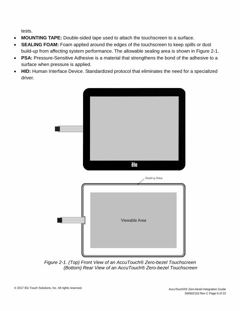
tests. • MOUNTING TAPE: Double-sided tape used to attach the touchscreen to a surface. • SEALING FOAM: Foam applied around the edges of the touchscreen to keep spills or dust
build-up from affecting system performance. The allowable sealing area is shown in Figure 2-1. • PSA: Pressure-Sensitive Adhesive is a material that strengthens the bond of the adhesive to a
surface when pressure is applied. • HID: Human Interface Device. Standardized protocol that eliminates the need for a specialized
driver.
Figure 2-1. (Top) Front View of an AccuTouch® Zero-bezel Touchscreen
(Bottom) Rear View of an AccuTouch® Zero-bezel Touchscreen

© 2017 Elo Touch Solutions, Inc. All rights reserved. AccuTouch®® Zero-bezel Integration Guide SW602153 Rev C Page 9 of 23
Integration Design Several options exist in the design and integration of the screen. The cross-sections of reference integration designs for an AccuTouch® touchscreen are illustrated in Figures 2-2 through Figure 2-5. Important elements of the integration are described in the sections that follow.
Standard
The standard AccuTouch® Zero-Bezel design matches the edge of the coversheet with the edge of the glass with a tolerance of 0.3mm.
Figure 2-2. Standard Design AccuTouch® Zero-Bezel Touchscreen
Overhang
Elo Touch Solutions can alternatively design the AccuTouch® Zero-bezel screen to have an overhang. This will guarantee that no raw glass is exposed. If the screen is not integrated properly, the overhang may cause buckling. If the sub-bezel is metal care must be taken that the edge of the coversheet does not touch or short out to the metal as this will adversely affect touch functionality. See the recommendation for gap tolerance in Figure 2-3.

© 2017 Elo Touch Solutions, Inc. All rights reserved. AccuTouch®® Zero-bezel Integration Guide SW602153 Rev C Page 10 of 23
Figure 2-3. Coversheet Overhang Design for AccuTouch® Zero-bezel Touchscreen
No Overhang
Elo Touch Solutions can design the AccuTouch® Zero-Bezel screen to never exhibit coversheet overhang. This guarantees that the coversheet will not extend past the edge of the raw glass, thus simplifying the integration process.
Figure 2-4. No Coversheet Overhang Design for AccuTouch® Zero-Bezel Touchscreen
AccuTouch® Zero-bezel touchscreens have been designed with a hole in the glass where the FPC cable exits. Elo Touch Solutions recommends that any sealing material be placed outside of this hole to prevent moisture and other materials from wicking into the screen. The bezel may be designed to accommodate the exiting cable as shown in Figure 2-5 below.
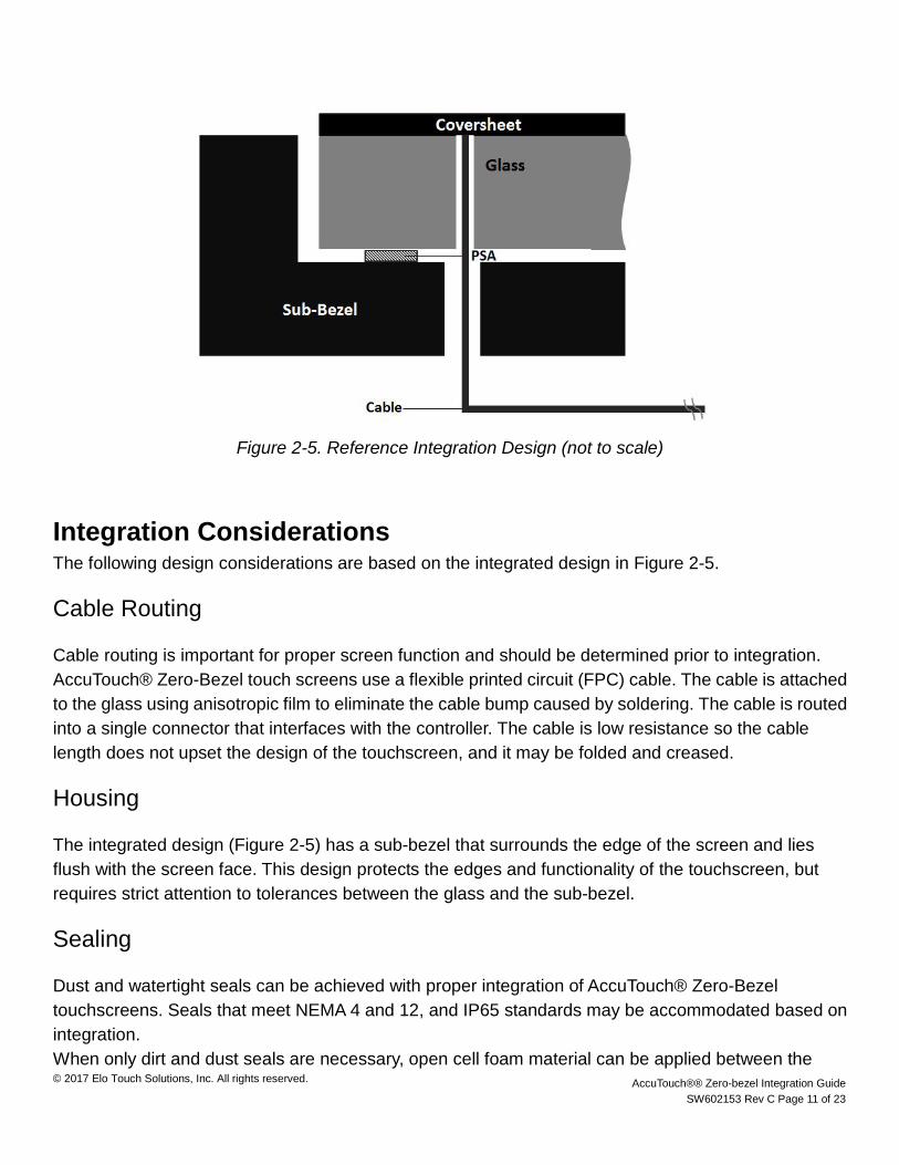
© 2017 Elo Touch Solutions, Inc. All rights reserved. AccuTouch®® Zero-bezel Integration Guide SW602153 Rev C Page 11 of 23
Figure 2-5. Reference Integration Design (not to scale)
Integration Considerations The following design considerations are based on the integrated design in Figure 2-5.
Cable Routing
Cable routing is important for proper screen function and should be determined prior to integration. AccuTouch® Zero-Bezel touch screens use a flexible printed circuit (FPC) cable. The cable is attached to the glass using anisotropic film to eliminate the cable bump caused by soldering. The cable is routed into a single connector that interfaces with the controller. The cable is low resistance so the cable length does not upset the design of the touchscreen, and it may be folded and creased.
Housing
The integrated design (Figure 2-5) has a sub-bezel that surrounds the edge of the screen and lies flush with the screen face. This design protects the edges and functionality of the touchscreen, but requires strict attention to tolerances between the glass and the sub-bezel.
Sealing
Dust and watertight seals can be achieved with proper integration of AccuTouch® Zero-Bezel touchscreens. Seals that meet NEMA 4 and 12, and IP65 standards may be accommodated based on integration. When only dirt and dust seals are necessary, open cell foam material can be applied between the
© 2017 Elo Touch Solutions, Inc. All rights reserved. AccuTouch®® Zero-bezel Integration Guide SW602153 Rev C Page 12 of 23
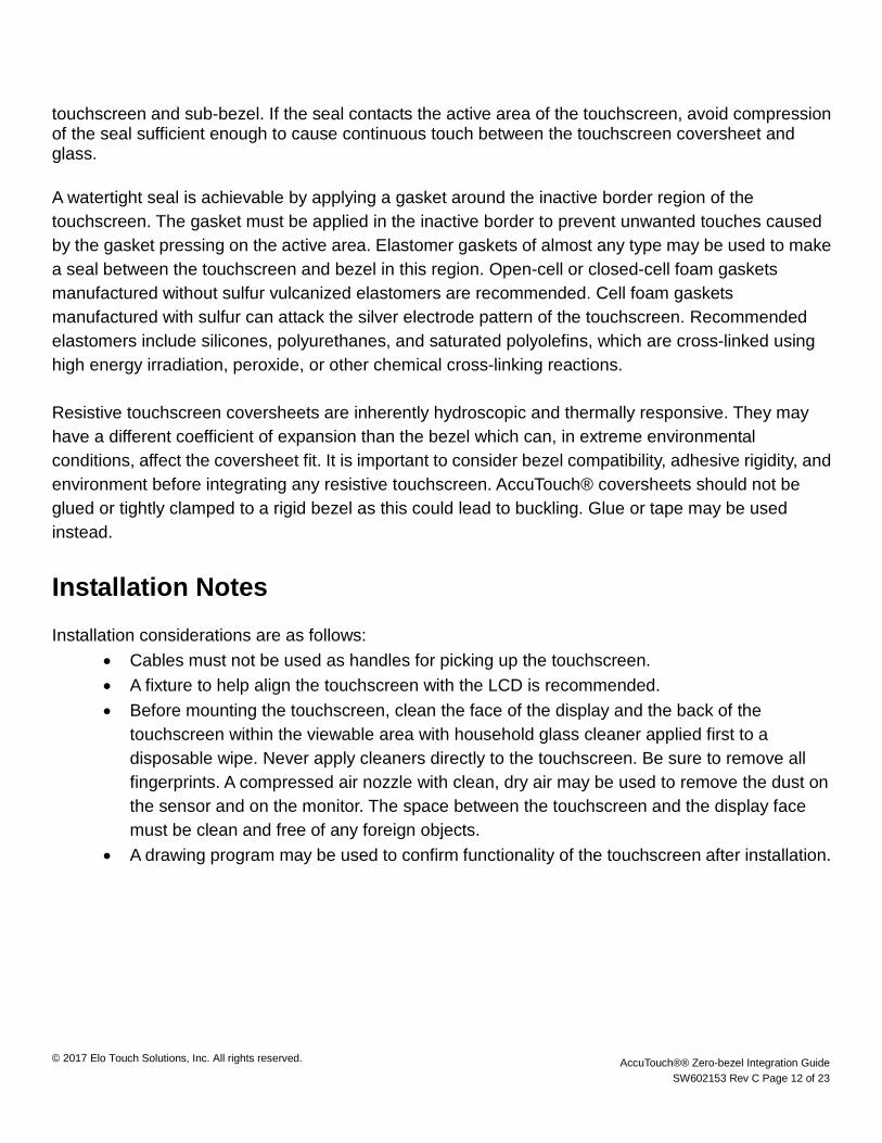
touchscreen and sub-bezel. If the seal contacts the active area of the touchscreen, avoid compression of the seal sufficient enough to cause continuous touch between the touchscreen coversheet and glass. A watertight seal is achievable by applying a gasket around the inactive border region of the touchscreen. The gasket must be applied in the inactive border to prevent unwanted touches caused by the gasket pressing on the active area. Elastomer gaskets of almost any type may be used to make a seal between the touchscreen and bezel in this region. Open-cell or closed-cell foam gaskets manufactured without sulfur vulcanized elastomers are recommended. Cell foam gaskets manufactured with sulfur can attack the silver electrode pattern of the touchscreen. Recommended elastomers include silicones, polyurethanes, and saturated polyolefins, which are cross-linked using high energy irradiation, peroxide, or other chemical cross-linking reactions. Resistive touchscreen coversheets are inherently hydroscopic and thermally responsive. They may have a different coefficient of expansion than the bezel which can, in extreme environmental conditions, affect the coversheet fit. It is important to consider bezel compatibility, adhesive rigidity, and environment before integrating any resistive touchscreen. AccuTouch® coversheets should not be glued or tightly clamped to a rigid bezel as this could lead to buckling. Glue or tape may be used instead.
Installation Notes Installation considerations are as follows:
• Cables must not be used as handles for picking up the touchscreen. • A fixture to help align the touchscreen with the LCD is recommended. • Before mounting the touchscreen, clean the face of the display and the back of the
touchscreen within the viewable area with household glass cleaner applied first to a disposable wipe. Never apply cleaners directly to the touchscreen. Be sure to remove all fingerprints. A compressed air nozzle with clean, dry air may be used to remove the dust on the sensor and on the monitor. The space between the touchscreen and the display face must be clean and free of any foreign objects.
• A drawing program may be used to confirm functionality of the touchscreen after installation.

© 2017 Elo Touch Solutions, Inc. All rights reserved. AccuTouch®® Zero-bezel Integration Guide SW602153 Rev C Page 13 of 23
Controller Considerations Elo will recommend the best controller for your application. The touchscreen has a cable to connect to the controller. The connection between the controller and computing system depends on the controller selected.
Figure 2-6. Basic system overview
AccuTouch® controllers should be securely mounted to a metal bracket with good grounding and mechanical support. The controller should also be mounted at least 100 mm away from sources of electrical noise.
It is recommended that the power for the controller be linked with the display power to prevent accidental computer inputs in the event that the controller is powered, but the display is off.

© 2017 Elo Touch Solutions, Inc. All rights reserved. AccuTouch®® Zero-bezel Integration Guide SW602153 Rev C Page 14 of 23
2218 Controller (PN E329179)
The Elo 2218 controller is a universal resistive touchscreen controller. It supports both serial and USB communication interfaces and is capable of interfacing to AccuTouch® five-wire resistive touchscreens.
The 2218 controller measures 35.00mm (1.38 inches) by 60.00mm (2.36 inches). Mounting holes located in two of the four corners have a diameter of 4.0mm (0.157 inches) and are centered 3.81mm (0.15 inches) from adjacent edges. The total height is 11.30mm (0.45 inches). Dimensional tolerances and further details are documented in Elo Touch Solutions specification for the printed circuit card.
Figure 2-7. 2218 Dimensions: Top View
Figure 2-8. 2218 Dimensions: Side View

© 2017 Elo Touch Solutions, Inc. All rights reserved. AccuTouch®® Zero-bezel Integration Guide SW602153 Rev C Page 15 of 23
COACh V Controller Chip (PN E196429)
The COACh V (Controller On A Chip, 5th generation) is a compact universal resistive touchscreen controller chip solution. It supports communication with serial and USB interfaces. Regardless of configuration, operation is automatically detected on power up and needs no user intervention. The COACh V fully supports the Elo SmartSet protocol and all program drivers, both serial and USB.
The COACh V controller chip measures 7mm (0.28 inches) by 7mm (0.28 inches) overall.
Features: • Single chip ASIC design for compact integration • Supports both USB and RS232 interfaces with auto-detection • Improved measurement algorithm eliminates the need for touch filter adjustments • Full AccuTouch® SmartSet protocol • Multiple output formats: Binary or ASCII • On-board calibration, coordinate scaling, and programmable output rates allow for
application-specific performance tuning
Figure 2-9. Pin Configuration for COACh V Controller Chip

© 2017 Elo Touch Solutions, Inc. All rights reserved. AccuTouch®® Zero-bezel Integration Guide SW602153 Rev C Page 16 of 23
Chapter 3: Troubleshooting If your integrated system is having functionality problems, there are several ways in which you can troubleshoot.
Troubleshooting the touchscreen The first suggested course of action is to connect an ohmmeter between pin 3 and another pin (1, 2, 4, or 5) of the touchscreen cable. This should show an open circuit (>2M ohms) when the touchscreen is not being touched. It should report <3000 ohms when touched in the middle of the touchscreen with firm finger pressure. A resistance of less than 3000 ohms will usually register a touch with the controller. Resistances up to 2M ohms without a touch will cause linearity problems, as the touchscreen system effectively averages a deliberate touch with the problem area. When these low resistance values are observed, look for bezel contact in the active area or damage to the cover sheet of the touchscreen.
If damage is suspected, monitor the resistance as described above while pulling gently on the cover sheet at the damaged location with a piece of tape stuck to the touchscreen coversheet. The resistance will increase to the normal open circuit value if the correct spot has been identified. It is possible, in some circumstances, to correct touchscreen shorts that result from damage to the cover sheet. Contact Elo Technical Support for additional information.
Figure 3-1. Touchscreen cable header
Most touchscreens will have pin-to-pin (1-2, 1-4, 1-5, 2-4, 2-5, 4-5) resistances smaller than 120 ohms. Also, the resistances are usually proportional to the relative distances between the corners for a particular size of touchscreen. Do not count on consistent resistance values from touchscreen to touchscreen. In general, large variations in resistance pairs, or absolute values above 120 ohms indicate a faulty touchscreen. Touchscreens with this type of damage are not repairable.

© 2017 Elo Touch Solutions, Inc. All rights reserved. AccuTouch®® Zero-bezel Integration Guide SW602153 Rev C Page 17 of 23
Troubleshooting the controller
The first step in troubleshooting the controller is verifying that it is powered properly. Most Elo controllers operate on a 5 V-dc power source. The LED should be lit or blinking. Please double check the specific requirements for the controller you are using to ensure you are within the specified range.
The second step is to verify proper controller grounding, which is essential for controller functionality. Grounding allows the controller to deal with electrical noise and other environmental issues. Elo controllers are designed with Plated Through Holes (PTH) for Earth grounding of the system. Ensure that one or more of the PTH is used, and that the PTH is connected to Earth to prevent undesired controller operation. In systems where direct mounting to an Earth chassis is not possible, Elo recommends the implementation of a grounding strap to connect one PTH to Earth.
Further diagnostics are available from the LED on Elo controllers. The LED can be used to determine:
Power is applied (On or blinking) Power On Self Test passes (Blinking at 1 time per second when not touched) Power On Self Test fails (Blinking at 2-3 times per second) Touch detected (Solid)
Give the system 20 seconds to stabilize after power is applied. The LED should blink once per second, and remain solid when the screen is touched. Once the touch is removed, the LED will return to the once per second blink. A fast blink may indicate failure of a particular system. Check the connections and, if needed, substitute the touchscreen. Power down the controller before each test as the diagnostics will reinitiate upon power up. If the fast blinking condition is still present, please contact Elo Technical Support for additional information.
If your controller is equipped with a second diagnostic LED, this is used to indicate proper USB communication. The LED will remain off until the HOST has enumerated the device. If the device does not enumerate, suspect USB cabling and/or USB HOST port. Substitution is the best for of troubleshooting in this case.

© 2017 Elo Touch Solutions, Inc. All rights reserved. AccuTouch®® Zero-bezel Integration Guide SW602153 Rev C Page 18 of 23
Troubleshooting the driver Elo driver software provides a consistent software interface among all Elo touchscreens and controllers. The driver software scales the absolute coordinates received from the touchscreen controller into translated screen coordinates, using the calibration points obtained with the calibration program included with the driver software. The driver also performs other operations as directed by the application.
Install the appropriate driver for the operating system to be used. Drivers for most common operating systems can be found on the Support page at www.elotouch.com. A video alignment program runs automatically at the end of the installation process. The alignment program may be run at any time from the Control Panel or a Desktop shortcut. The standard calibration program requires the touch and release of three “targets.” A test screen shows confirmation of correct alignment. More precise alignment routines may be available upon request.
Connectivity to a touch device can be verified using the Device Manager in Windows operating systems. The touch device should show up under “Mice and other pointing devices.” After auto-detection, with no driver installed, it should report as a HID-compliant mouse. After successful driver installation it should report as a specific Elo Touch Solutions device.
In many cases, both serial and USB touch connectivity may be offered – use either one or the other; do not connect both serial and USB. The serial connector is similar in appearance to a VGA video connector, but the serial connector only has nine pins. The serial touch connector is usually very close to the USB connector.
When a USB touch connection is used, hardware functionality can be verified by touching the screen after auto-detection; even without any driver installed, there should be some response to touch by virtue of the touch system being a HID-compliant device (touch response may be radically misaligned with the video, but any sort of cursor movement on touch confirms basic hardware functionality).
There is very little troubleshooting to be done for the driver itself, other than verifying that the correct driver has been installed. If several incorrect drivers have been installed, it may be necessary to do a manual uninstall to “clean up” the operating system. In such a case, see the Manual Driver Removal instructions in the Support section of www.elotouch.com.

© 2017 Elo Touch Solutions, Inc. All rights reserved. AccuTouch®® Zero-bezel Integration Guide SW602153 Rev C Page 19 of 23
Chapter 4: Customization Options
This section of the manual provides a list of customization options and constraints.
Coversheet The coversheet can be designed with an overhang or no overhang upon request. Overhang may cause buckling but no raw glass will be visible. No overhang will leave more exposed glass.
Screen Thickness Standard AccuTouch® screens have a nominal glass thickness of 1.8, 2.4, and 3.2mm. Total screen thickness ranges from 2.12 to 3.52mm.
Corners The touchscreen design accommodates square or round corners with a recommended radius between 2 and 5 mm. Larger radii can be accommodated. Please contact Elo Touch Solutions if larger radii are required.
Mounting and Sealing Solution
Elo Touch Solutions can design and apply mounting tape or a sealing gasket for your application if needed. Design considerations include border width, mating material, touchscreen weight, and screen design. Tape and gasket thickness can be tuned to accommodate different needs.
Connector Type
Elo Touch Solutions can design the cable to fit the connector needed in your application. Elo standard housings are slim type (AMP 487378-4), latch type ( AMP 487526-4), and detent type ( AMP 487769-3). ZIF terminations are also possible with the use of FPC cable of some lengths.
© 2017 Elo Touch Solutions, Inc. All rights reserved. AccuTouch®® Zero-bezel Integration Guide SW602153 Rev C Page 20 of 23
Holes and Ink-Free Areas
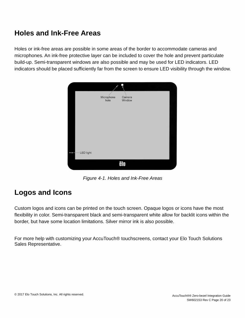
Holes or ink-free areas are possible in some areas of the border to accommodate cameras and microphones. An ink-free protective layer can be included to cover the hole and prevent particulate build-up. Semi-transparent windows are also possible and may be used for LED indicators. LED indicators should be placed sufficiently far from the screen to ensure LED visibility through the window.
Figure 4-1. Holes and Ink-Free Areas
Logos and Icons
Custom logos and icons can be printed on the touch screen. Opaque logos or icons have the most flexibility in color. Semi-transparent black and semi-transparent white allow for backlit icons within the border, but have some location limitations. Silver mirror ink is also possible.
For more help with customizing your AccuTouch® touchscreens, contact your Elo Touch Solutions Sales Representative.
© 2017 Elo Touch Solutions, Inc. All rights reserved. AccuTouch®® Zero-bezel Integration Guide SW602153 Rev C Page 21 of 23
Chapter 5: Frequently Asked Questions
This section covers the most common questions concerning AccuTouch® components.
1. What type of glass is used? Standard AccuTouch® screens are available with soda lime glass. The nominal glass thickness is between 1.8 and 3.2mm. 2. What is the screen thickness? The screen thickness is between 2.12 and 3.52mm. 3. What border width is expected from an AccuTouch® Zero-Bezel touchscreen? The width of the border is dependent on the dimensions of the touchscreen and/or active area. Elo design engineers make every effort to reduce border width if required by the customer, while maintaining integrity of the touch response. 4. What finishes are available on AccuTouch® Zero-bezel screens? Elo AccuTouch® Zero-bezel screens are designed with an anti-glare finish. 5. Can I have a drilled hole for a microphone or camera? Elo can provide circular, drilled holes with diameters between 0.5mm and 2.0mm. Additionally, ink-free areas of various shapes may be used. 6. Can I choose the cable connector type? Standard AccuTouch® Zero-Bezel screens come with a latch, slim, or detent type housing. ZIF terminations are available upon request. 7. Can I pick the cable length? Elo offers several standard screens with a specific cable length as provided on the Elo website. Please contact an Elo Representative if a custom cable length is needed. 8. What are my corner radius options? Elo Touch Solutions recommends a radius between 2 and 5mm for the corners. Square edges are also possible. For larger radii, please contact Elo to accommodate the design.

© 2017 Elo Touch Solutions, Inc. All rights reserved. AccuTouch®® Zero-bezel Integration Guide SW602153 Rev C Page 22 of 23
9. Will mounting tape or sealing materials be prepared by Elo? Mounting and sealing is typically completed by the customer. Elo Touch Solutions can apply mounting tape or design a sealing gasket for you upon request. See the sealing section of Chapter 2 for more details. 10. How can I test functionality after integration? The functionality will depend on the applications and operating system used for the device. In general, a drawing program is helpful for ensuring that the system works properly after integration. 11. Where can I find more information if my questions aren’t answered in the AccuTouch® Zero-Bezel Integration Guide? Contact Elo Touch Solutions Customer Sales and Support for help with any further questions about your AccuTouch® application.

© 2017 Elo Touch Solutions, Inc. All rights reserved. AccuTouch®® Zero-bezel Integration Guide SW602153 Rev C Page 23 of 23
Check out our website
www.EloEmbedded.com
Get the latest...
• Product Information
• Specifications
• Upcoming events
• Press releases
• Software drivers
Getting in Touch with Us
To find out more about the extensive range of Elo touch solutions, visit our website at www.elotouch.com, or simply call the office nearest you:
North America Elo Touch Solutions 1033 McCarthy Blvd Milpitas, CA 95035
Tel 800-ELO-TOUCH Tel + 1 408 597 8000 Fax +1 408 597 8050 [email protected]
Europe Tel +32 (0) 16 70 45 00 Fax +32 (0)16 70 45 49 [email protected]
Asia-Pacific Tel +86 (21) 6106 7162 Fax +86 (21) 6485 3981 www.elotouch.com.cn
Latin America Tel 786-923-0251 Fax 305-931-0124 www.elotouch.com