ElmerGUI manual v. 0 - nic.funet.fi · ElmerGUI manual v. 0.2 Mikko Lyly November 26, 2008 1....
37
ElmerGUI manual v. 0.2 Mikko Lyly November 26, 2008 1
Transcript of ElmerGUI manual v. 0 - nic.funet.fi · ElmerGUI manual v. 0.2 Mikko Lyly November 26, 2008 1....
ElmerGUI manual v. 0.2
Mikko Lyly
November 26, 2008
1
Contents
1 Introduction 3
2 Installation from source 42.1 Linux . . . . . . . . . . . . . . . . . . . . . . . . . . . . . . . 42.2 Windows . . . . . . . . . . . . . . . . . . . . . . . . . . . . . . 5
3 Input files 63.1 Geometry input files and mesh generation . . . . . . . . . . . 63.2 Elmer mesh files . . . . . . . . . . . . . . . . . . . . . . . . . . 73.3 Project files . . . . . . . . . . . . . . . . . . . . . . . . . . . . 7
4 Model definitions 84.1 Setup menu . . . . . . . . . . . . . . . . . . . . . . . . . . . . 84.2 Equation menu . . . . . . . . . . . . . . . . . . . . . . . . . . 84.3 Material menu . . . . . . . . . . . . . . . . . . . . . . . . . . . 94.4 Body force menu . . . . . . . . . . . . . . . . . . . . . . . . . 114.5 Initial condition menu . . . . . . . . . . . . . . . . . . . . . . 114.6 Boundary condition menu . . . . . . . . . . . . . . . . . . . . 12
5 Utility functions 135.1 Boundary division and unification . . . . . . . . . . . . . . . . 135.2 Saving pictures . . . . . . . . . . . . . . . . . . . . . . . . . . 155.3 View menu . . . . . . . . . . . . . . . . . . . . . . . . . . . . 15
6 Solver input files 16
7 Solution and post processing 167.1 Running the solver . . . . . . . . . . . . . . . . . . . . . . . . 167.2 Post preocessor . . . . . . . . . . . . . . . . . . . . . . . . . . 18
A ElmerGUI initialization file 18
B ElmerGUI material database 21
C ElmerGUI definition files 22
D Elmer mesh files 25
2

1 Introduction
ElmerGUI is a graphical user interface for the Elmer software suite [?]. Theprogram is capable of importing finite element mesh files in various for-mats, generating finite element partitionings for models with piecewise linearboundaries, setting up PDE-systems to solve, and exporting model data andresults for ElmerSolver and ElmerPost to visualize. There is also an internalpostprocessor, which can be used as an alternative to ElmerPost, to drawcolor surfaces, contours, vector fields, and visualize time dependent data.
Figure 1: Main window of ElmerGUI.
One of the main features of ElmerGUI is the interface to the parallelsolver, ElmerSolver mpi. The GUI hides from the user a number of opera-tions that are normally performed from command line with various externaltools related to domain decomposition, launching the paralle processes, andmerging the results. This makes it possible to use ElmerSolver with multi-core processors even on interactive desktop environments.
The menus of ElmerGUI are programmable and it is relatively easy tostrip and customize the interface for an proprietary application. An exampleof customizing the menus is provided in appendix A.
3
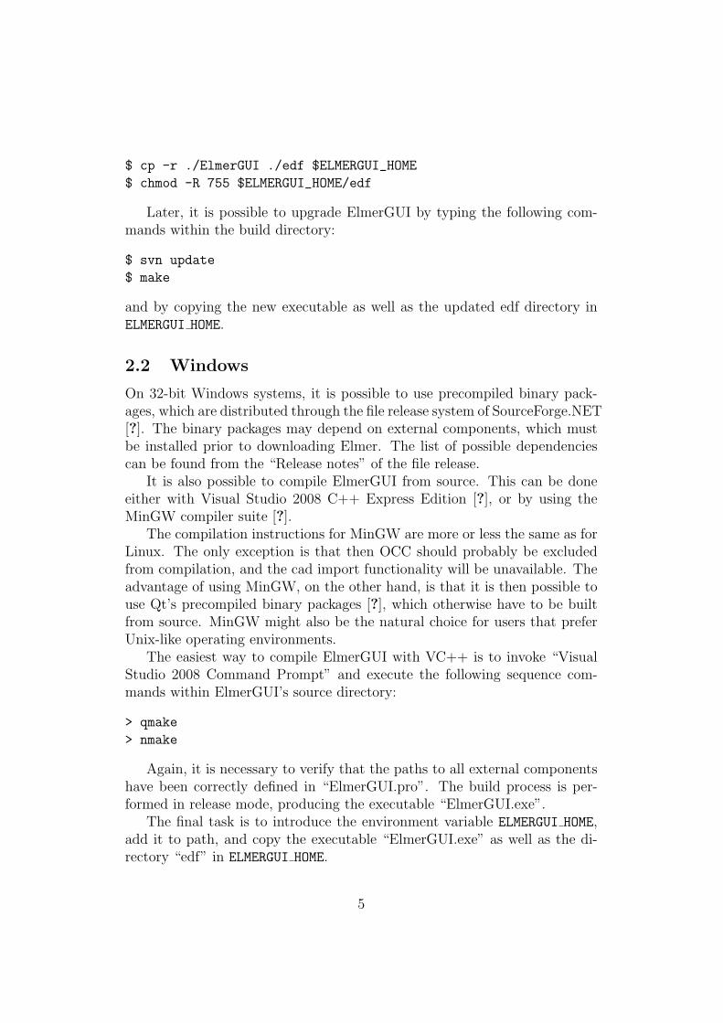
ElmerGUI relies on the Qt4 cross platform framework from Trolltech [?],and it uses the Qwt5 libray by Josef Wilgen and Uwe Rathman[?]. Theinternal postprocessor is based on the VTK library of Ken Martin, WillSchroeder, and Bill Lorensen [?]. The CAD import features are implementedby linking against the OCC library fromOpenCASCADE S.A.S. [?]. Theprogram is also capable of using Tetgen [?] and Netgen [?] as external finiteelement mesh generators.
2 Installation from source
The source code of ElmerGUI is available from the subversion repository ofSourceForge.Net. The GPL licenced source may be downloaded by executingthe following command with a SVN client program(on Windows the TortoiseSVN client is recommended):
svn co https://elmerfem.svn.sourceforge.net/svnroot/elmerfem/trunk trunk
This will retrieve the current development version of the whole Elmer-suite.
2.1 Linux
Bofore staring to compile, please make sure that you have the developmentpackage of Qt 4 installed on your system (i.e., libraries, headers, and programdevelopment tools). Qt version 4.2 or newer is recommended. You may alsowish to install Qwt 5, VTK version 5, and OpenCASCADE 6.3, for additionalfunctionality.
The program is compiled by executing the following sequence of com-mands in a terminal window:
$ cd elmerfem/trunk/ElmerGUI
$ qmake
$ make
It is possible that the project file “ElmerGUI.pro” needs to be editeddepending on how and where the external libraries have been installed. Thelines that need attention can be found from the beginning of the file.
Once the build process has finished, it suffices to set up the environmentvariable ELMERGUI HOME, add it to PATH, and copy the file “ElmerGUI” andthe directory “edf” in this location:
$ export ELMERGUI_HOME=$ELMER_HOME/bin
$ export PATH=$PATH:$ELMERGUI_HOME
4
$ cp -r ./ElmerGUI ./edf $ELMERGUI_HOME
$ chmod -R 755 $ELMERGUI_HOME/edf
Later, it is possible to upgrade ElmerGUI by typing the following com-mands within the build directory:
$ svn update
$ make
and by copying the new executable as well as the updated edf directory inELMERGUI HOME.
2.2 Windows
On 32-bit Windows systems, it is possible to use precompiled binary pack-ages, which are distributed through the file release system of SourceForge.NET[?]. The binary packages may depend on external components, which mustbe installed prior to downloading Elmer. The list of possible dependenciescan be found from the “Release notes” of the file release.
It is also possible to compile ElmerGUI from source. This can be doneeither with Visual Studio 2008 C++ Express Edition [?], or by using theMinGW compiler suite [?].
The compilation instructions for MinGW are more or less the same as forLinux. The only exception is that then OCC should probably be excludedfrom compilation, and the cad import functionality will be unavailable. Theadvantage of using MinGW, on the other hand, is that it is then possible touse Qt’s precompiled binary packages [?], which otherwise have to be builtfrom source. MinGW might also be the natural choice for users that preferUnix-like operating environments.
The easiest way to compile ElmerGUI with VC++ is to invoke “VisualStudio 2008 Command Prompt” and execute the following sequence com-mands within ElmerGUI’s source directory:
> qmake
> nmake
Again, it is necessary to verify that the paths to all external componentshave been correctly defined in “ElmerGUI.pro”. The build process is per-formed in release mode, producing the executable “ElmerGUI.exe”.
The final task is to introduce the environment variable ELMERGUI HOME,add it to path, and copy the executable “ElmerGUI.exe” as well as the di-rectory “edf” in ELMERGUI HOME.
5

3 Input files
3.1 Geometry input files and mesh generation
ElmerGUI is capable of importing finite element mesh files and generatingtwo or three dimensional finite element partitionings for bounded domainswith piecewise linear boundaries. It is possible to use one of the followingmesh generators:
• ElmerGrid (built-in)
• Tetgen (optional)
• Netgen (optional)
The default import filter and mesh generator is ElmerGrid. Tetgen andNetgen are optional modules, which may or may not be available dependingon the installation (installation and compilation instructions can be foundfrom Elmer’s source tree in trunk/misc)
An import filter or a mesh generator is selected automatically by Elmer-GUI when a geometry input file is opened from the File menu:
File → Open...
The selection is based on the input file suffix according to Table 1. Iftwo or more generators are capable of handing the same format, then theuser defined “preferred generator” will be used. The preferred generator isdefined in
Mesh → Configure...
Once the input file has been opened, it is possible to modify the meshparameters and remesh the geometry for better accuracy or computationalefficiency. The mesh parameters can be found from the same place as thepreferred generator. The control string for Tetgen has been discussed andexplained in detail in [?].
6
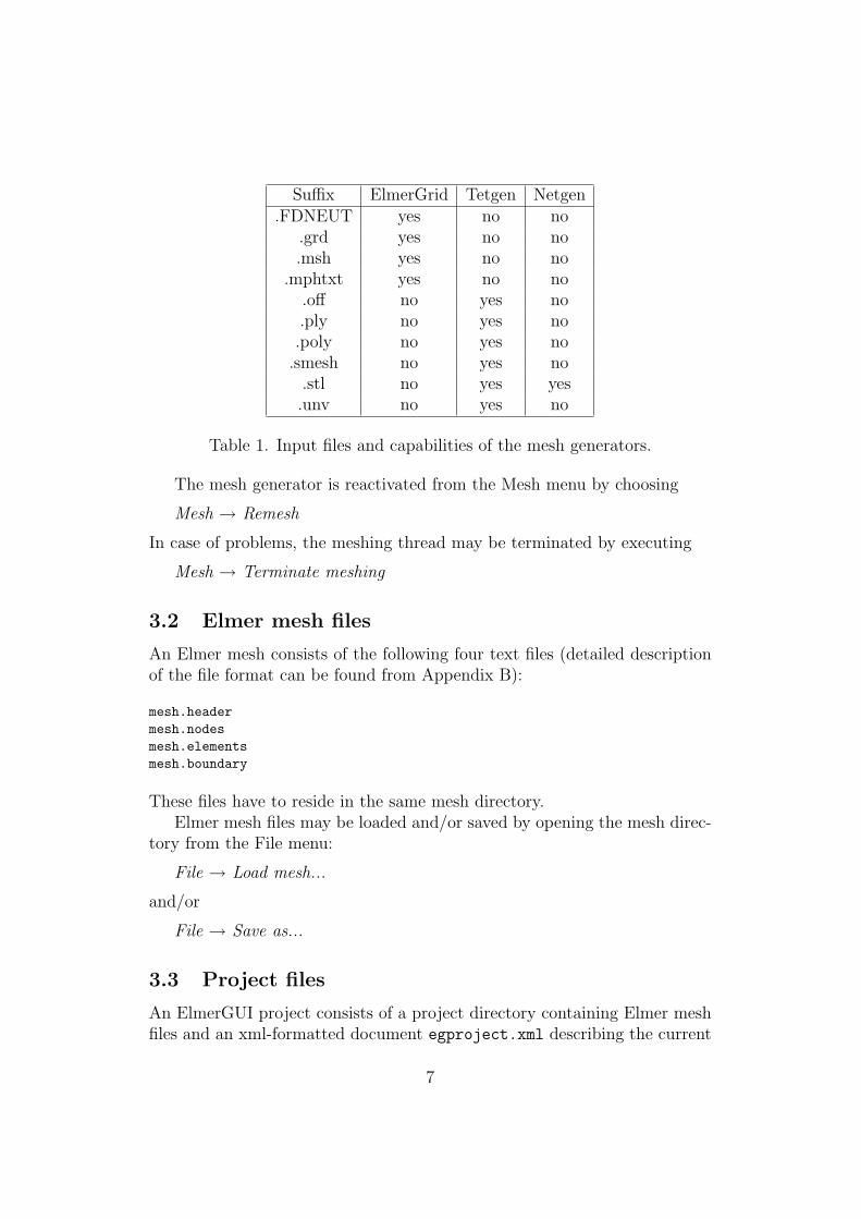
Suffix ElmerGrid Tetgen Netgen.FDNEUT yes no no
.grd yes no no.msh yes no no
.mphtxt yes no no.off no yes no.ply no yes no.poly no yes no
.smesh no yes no.stl no yes yes.unv no yes no
Table 1. Input files and capabilities of the mesh generators.
The mesh generator is reactivated from the Mesh menu by choosing
Mesh → Remesh
In case of problems, the meshing thread may be terminated by executing
Mesh → Terminate meshing
3.2 Elmer mesh files
An Elmer mesh consists of the following four text files (detailed descriptionof the file format can be found from Appendix B):
mesh.headermesh.nodesmesh.elementsmesh.boundary
These files have to reside in the same mesh directory.Elmer mesh files may be loaded and/or saved by opening the mesh direc-
tory from the File menu:
File → Load mesh...
and/or
File → Save as...
3.3 Project files
An ElmerGUI project consists of a project directory containing Elmer meshfiles and an xml-formatted document egproject.xml describing the current
7
state and settings. Projects may be loaded and/or saved from the File menuas
File → Load project...
and/or
File → Save project...
When an ElmerGUI project is loaded, a new solver input file will begenerated and saved in the project directory using the sif-name defined in
Model → Setup...
If there is an old solver input file with the same name, it will be overwritten.The contents of a typical project directory is the following:
case.sifegproject.xmlELMERSOLVER_STARTINFOmesh.boundarymesh.elementsmesh.headermesh.nodes
4 Model definitions
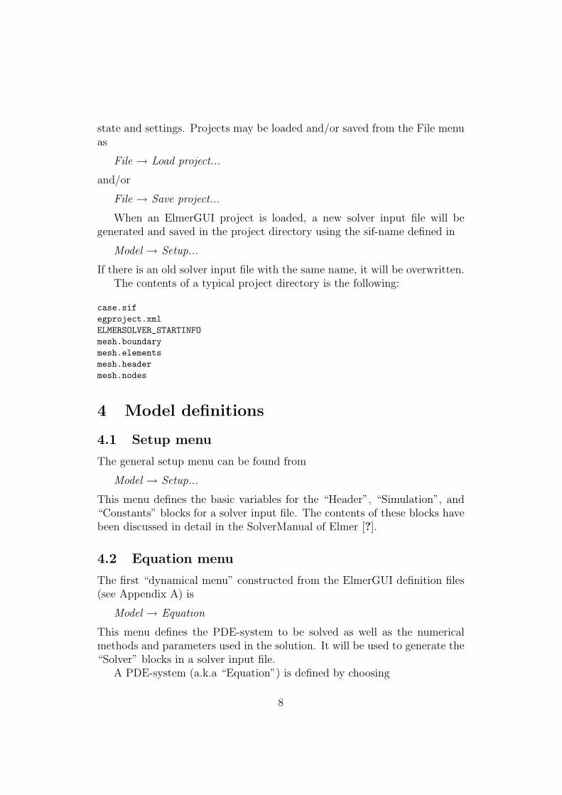
4.1 Setup menu
The general setup menu can be found from
Model → Setup...
This menu defines the basic variables for the “Header”, “Simulation”, and“Constants” blocks for a solver input file. The contents of these blocks havebeen discussed in detail in the SolverManual of Elmer [?].
4.2 Equation menu
The first “dynamical menu” constructed from the ElmerGUI definition files(see Appendix A) is
Model → Equation
This menu defines the PDE-system to be solved as well as the numericalmethods and parameters used in the solution. It will be used to generate the“Solver” blocks in a solver input file.
A PDE-system (a.k.a “Equation”) is defined by choosing
8
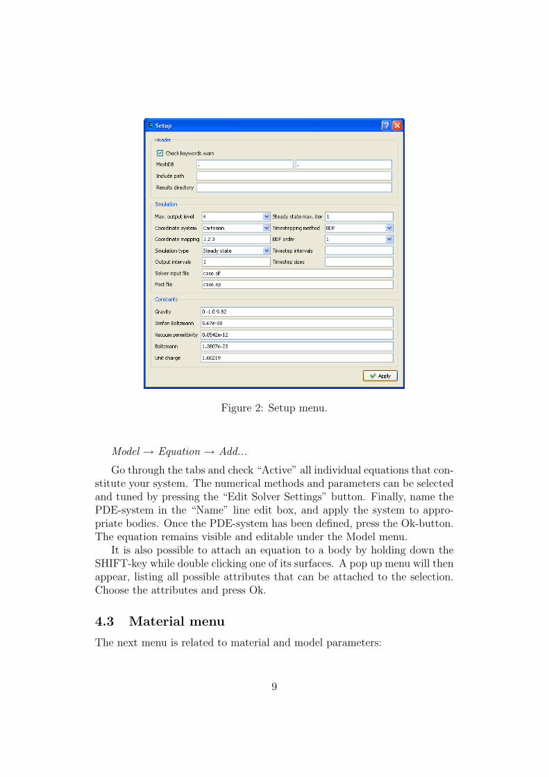
Figure 2: Setup menu.
Model → Equation → Add...
Go through the tabs and check “Active” all individual equations that con-stitute your system. The numerical methods and parameters can be selectedand tuned by pressing the “Edit Solver Settings” button. Finally, name thePDE-system in the “Name” line edit box, and apply the system to appro-priate bodies. Once the PDE-system has been defined, press the Ok-button.The equation remains visible and editable under the Model menu.
It is also possible to attach an equation to a body by holding down theSHIFT-key while double clicking one of its surfaces. A pop up menu will thenappear, listing all possible attributes that can be attached to the selection.Choose the attributes and press Ok.
4.3 Material menu
The next menu is related to material and model parameters:
9
Figure 3: Equation menu.
Model → Material
This menu will be used to generate the “Material” blocks in a solver inputfile.
In order to define a material parameter set and attach it to bodies, choose
Model → Material → Add...
Again, it is possible to attach the material to a body by holding downthe SHIFT-key while double clicking one of its boundaries.
Note: The value of density should always be defined in the “General”tab. This field should never be left undefined.
If you set focus in a line edit box of a dynamical menu and press Enter, asmall text edit dialog will pop up. This allows the input of more complicatedexpressions than just constants. As an example, go to Model→ Material andchoose Add... Place the cursor in the “Heat conductivity” line edit box of“Heat equation” and press Enter. You can then define the heat conductivityas a function of temperature as a piecewise linear function. An example isshow in Figure N. In this case, the heat conductivity gets value 10 if thetemperature is less than 273 degrees. It then rises from 10 to 20 between 273and 373 degrees, and remains constant 20 above 373 degrees.
10

Figure 4: Solver settings menu.
If the user presses SHIFT and F1, a tooltip for the active widget will bedisplayed.
4.4 Body force menu
The next menu in the list is
Model → Body force
This menu is used to construct the “Body force” blocks in a solver input file.Again, choose
Model → Body force → Add...
to define a set of body forces and attach it to the bodies.
4.5 Initial condition menu
The last menu related to body properties is
Model → Initial condition
Once again, choose
11
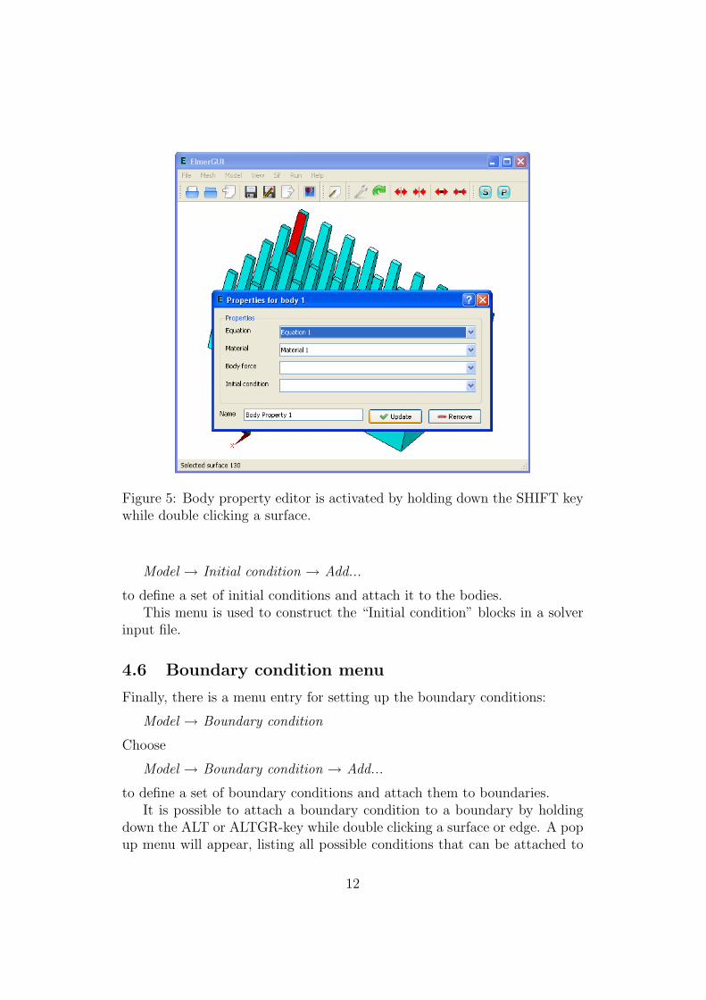
Figure 5: Body property editor is activated by holding down the SHIFT keywhile double clicking a surface.
Model → Initial condition → Add...
to define a set of initial conditions and attach it to the bodies.This menu is used to construct the “Initial condition” blocks in a solver
input file.
4.6 Boundary condition menu
Finally, there is a menu entry for setting up the boundary conditions:
Model → Boundary condition
Choose
Model → Boundary condition → Add...
to define a set of boundary conditions and attach them to boundaries.It is possible to attach a boundary condition to a boundary by holding
down the ALT or ALTGR-key while double clicking a surface or edge. A popup menu will appear, listing all possible conditions that can be attached to
12
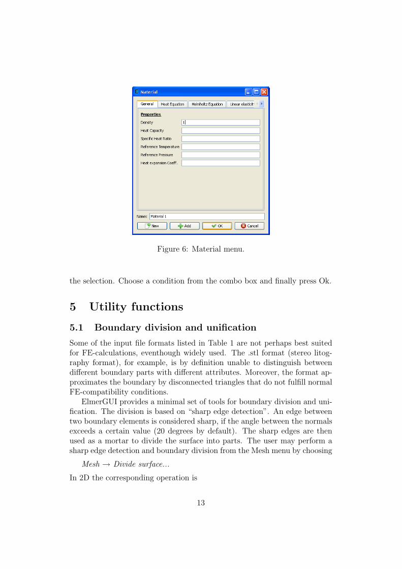
Figure 6: Material menu.
the selection. Choose a condition from the combo box and finally press Ok.
5 Utility functions
5.1 Boundary division and unification
Some of the input file formats listed in Table 1 are not perhaps best suitedfor FE-calculations, eventhough widely used. The .stl format (stereo litog-raphy format), for example, is by definition unable to distinguish betweendifferent boundary parts with different attributes. Moreover, the format ap-proximates the boundary by disconnected triangles that do not fulfill normalFE-compatibility conditions.
ElmerGUI provides a minimal set of tools for boundary division and uni-fication. The division is based on “sharp edge detection”. An edge betweentwo boundary elements is considered sharp, if the angle between the normalsexceeds a certain value (20 degrees by default). The sharp edges are thenused as a mortar to divide the surface into parts. The user may perform asharp edge detection and boundary division from the Mesh menu by choosing
Mesh → Divide surface...
In 2D the corresponding operation is
13

Figure 7: Tooltips are shown by holding down the SHIFT and F1 keys.
Mesh → Divide edge...
The resulting parts are enumerated starting from the first free index.Sometimes, the above process produces far too many distinct parts, which
eventually need to be (re)unified. This can be done by selecting a group ofsurfaces by holding down the CTRL-key while double clicking the surfacesand choosing
Mesh → Unify surface...
The same operation in 2D is
Mesh → Unify edge...
The result will inherit the smallest index from the selected group.The sharp edges that do not belong to a closed loop may be removed by
Mesh → Clean up
This operation has no effect on the boundary division, but sometimes itmakes the result look better.
14
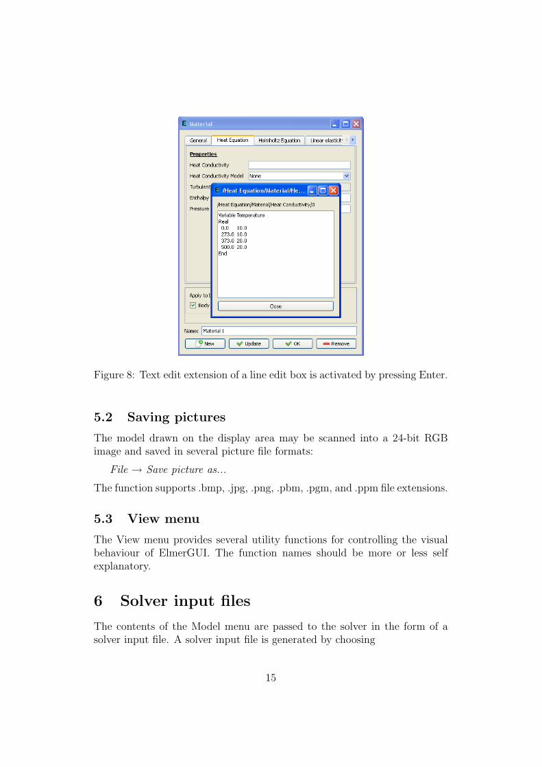
Figure 8: Text edit extension of a line edit box is activated by pressing Enter.
5.2 Saving pictures
The model drawn on the display area may be scanned into a 24-bit RGBimage and saved in several picture file formats:
File → Save picture as...
The function supports .bmp, .jpg, .png, .pbm, .pgm, and .ppm file extensions.
5.3 View menu
The View menu provides several utility functions for controlling the visualbehaviour of ElmerGUI. The function names should be more or less selfexplanatory.
6 Solver input files
The contents of the Model menu are passed to the solver in the form of asolver input file. A solver input file is generated by choosing
15
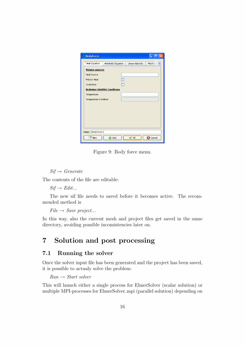
Figure 9: Body force menu.
Sif → Generate
The contents of the file are editable:
Sif → Edit...
The new sif file needs to saved before it becomes active. The recom-mended method is
File → Save project...
In this way, also the current mesh and project files get saved in the samedirectory, avoiding possible inconsistencies later on.
7 Solution and post processing
7.1 Running the solver
Once the solver input file has been generated and the project has been saved,it is possible to actualy solve the problem:
Run → Start solver
This will launch either a single process for ElmerSolver (scalar solution) ormultiple MPI-processes for ElmerSolver mpi (parallel solution) depending on
16

Figure 10: Initial condition menu.
the definitions in
Run → Parallel settings...
The parallel menu has three group boxes. Usually, the user is supposed totouch only the “General settings” group and select the number of processes toexecute. The two remaining groups deal with system commands to launchMPI-processes and external tools for domain decomposition. The parallelmenu is greyed out if ElmerSolver mpi is not present at start-up.
When the solver is running, there is a log window and a convergencemonitor from which the iteration may be followed. In case of divergence orother troubles, the solver may be terminated by choosing
Run → Kill solver
The solver will finally write a result file for ElmerPost in the projectdirectory. The name of the ep-file is defined in
Model → Setup...
7.2 Post preocessor
The post processor is activated from
Run → Start postprocessor
17

Figure 11: Boundary condition menu.
This will launch ElmerPost, which will read in the results and displays acontour plot representing the solution. If the results were prodoced by theparallel solver, the domain decomposition used in the calculations will beshown.
A ElmerGUI initialization file
The initialization file for ElmerGUI is located in ELMERGUI HOME/edf. It iscalled egini.xml:
<?xml version=’1.0’ encoding=’UTF-8’?><!DOCTYPE egini><egini version="1.0">
Show splash screen at startup:<splashscreen> 1 </splashscreen>
Show system tray icon:<systrayicon> 1 </systrayicon>
Show system tray messages:<systraymessages> 1 </systraymessages>
18
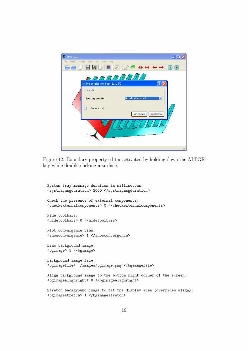
Figure 12: Boundary property editor activated by holding down the ALTGRkey while double clicking a surface.
System tray message duration in millisecons:<systraymsgduration> 3000 </systraymsgduration>
Check the presence of external components:<checkexternalcomponents> 0 </checkexternalcomponents>
Hide toolbars:<hidetoolbars> 0 </hidetoolbars>
Plot convergence view:<showconvergence> 1 </showconvergence>
Draw background image:<bgimage> 1 </bgimage>
Background image file:<bgimagefile> :/images/bgimage.png </bgimagefile>
Align background image to the bottom right corner of the screen:<bgimagealignright> 0 </bgimagealignright>
Stretch background image to fit the display area (overrides align):<bgimagestretch> 1 </bgimagestretch>
19

Figure 13: Parallel settings dialog.
Maximum number of solvers / equation:<max_solvers> 10 </max_solvers>
Maximum number of equations:<max_equations> 10 </max_equations>
Maximum number of materials:<max_materials> 10 </max_materials>
Maximum number of bodyforces:<max_bodyforces> 10 </max_bodyforces>
Maximum number of initial conditions:<max_initialconditions> 10 </max_initialconditions>
Maximum number of bodies:<max_bodies> 100 </max_bodies>
Maximum number of bcs:<max_bcs> 500 </max_bcs>
Maximum number of boundaries:
20
<max_boundaries> 500 </max_boundaries>
</egini>
You may change the default behaviour of ElmerGUI by editing this file.For example, to turn off the splash screen at start up, change the value of thetag <splshscreen> from 1 to 0. To change the background image, enter apicture file name in the <bgimagefile> tag. You might also want to increasethe default values for solvers, equations, etc., in case of very complex models.
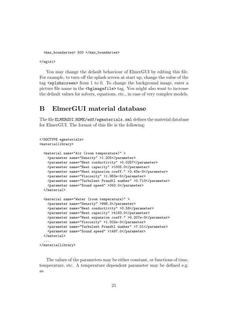
B ElmerGUI material database
The file ELMERGUI HOME/edf/egmaterials.xml defines the material databasefor ElmerGUI. The format of this file is the following:
<!DOCTYPE egmaterials><materiallibrary>
<material name="Air (room temperature)" ><parameter name="Density" >1.205</parameter><parameter name="Heat conductivity" >0.0257</parameter><parameter name="Heat capacity" >1005.0</parameter><parameter name="Heat expansion coeff." >3.43e-3</parameter><parameter name="Viscosity" >1.983e-5</parameter><parameter name="Turbulent Prandtl number" >0.713</parameter><parameter name="Sound speed" >343.0</parameter>
</material>
<material name="Water (room temperature)" ><parameter name="Density" >998.3</parameter><parameter name="Heat conductivity" >0.58</parameter><parameter name="Heat capacity" >4183.0</parameter><parameter name="Heat expansion coeff." >0.207e-3</parameter><parameter name="Viscosity" >1.002e-3</parameter><parameter name="Turbulent Prandtl number" >7.01</parameter><parameter name="Sound speed" >1497.0</parameter>
</material>...
</materiallibrary>
The values of the parameters may be either constant, or functions of time,temperature, etc. A temperature dependent parameter may be defined e.g.as
21
<parameter name="A" >Variable Temperature; Real; 2 3; 4 5; End</parameter>
In this case, A(2) = 3 and A(4) = 5. Values between the points are interpo-lated linearly, and extrapolated in the tangent direction outside the domain.The number of points defining he interpolant may be arbitrary.
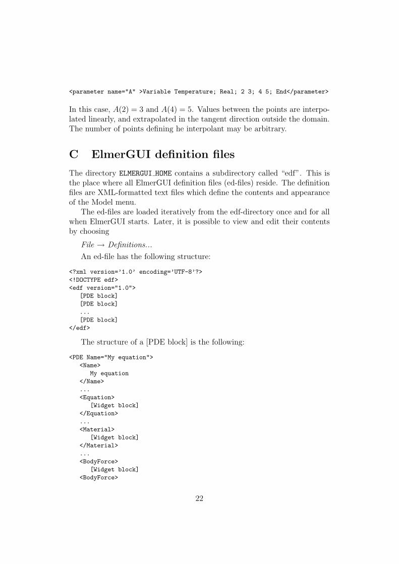
C ElmerGUI definition files
The directory ELMERGUI HOME contains a subdirectory called “edf”. This isthe place where all ElmerGUI definition files (ed-files) reside. The definitionfiles are XML-formatted text files which define the contents and appearanceof the Model menu.
The ed-files are loaded iteratively from the edf-directory once and for allwhen ElmerGUI starts. Later, it is possible to view and edit their contentsby choosing
File → Definitions...
An ed-file has the following structure:
<?xml version=’1.0’ encoding=’UTF-8’?><!DOCTYPE edf><edf version="1.0">
[PDE block][PDE block]...[PDE block]
</edf>
The structure of a [PDE block] is the following:
<PDE Name="My equation"><Name>
My equation</Name>...<Equation>
[Widget block]</Equation>...<Material>
[Widget block]</Material>...<BodyForce>
[Widget block]<BodyForce>
22
...<InitialCondition>
[Widget block]</InitialCondition>...<BoundaryCondition>
[Widget block]</BoundaryCondition>
</PDE>
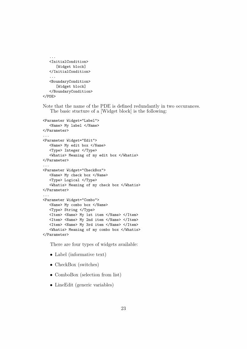
Note that the name of the PDE is defined redundantly in two occurances.The basic stucture of a [Widget block] is the following:
<Parameter Widget="Label"><Name> My label </Name>
</Parameter>...<Parameter Widget="Edit">
<Name> My edit box </Name><Type> Integer </Type><Whatis> Meaning of my edit box </Whatis>
</Parameter>...<Parameter Widget="CheckBox">
<Name> My check box </Name><Type> Logical </Type><Whatis> Meaning of my check box </Whatis>
</Parameter>...<Parameter Widget="Combo">
<Name> My combo box </Name><Type> String </Type><Item> <Name> My 1st item </Name> </Item><Item> <Name> My 2nd item </Name> </Item><Item> <Name> My 3rd item </Name> </Item><Whatis> Meaning of my combo box </Whatis>
</Parameter>
There are four types of widgets available:
• Label (informative text)
• CheckBox (switches)
• ComboBox (selection from list)
• LineEdit (generic variables)
23

Each widget must be given a name and and a variable type: logical, integer,real, or string. It is also a good practice to equip the widgets with tooltipsexplaining their purpose and meaning as clearly as possible.
Below is a working example of a minimal ElmerGUI definition file. It willadd “My equation” to the equation tabs in the Model menu, see Figure N.The file is called “sample.edf” and it should be placed in ELMERGUI HOME/edf.
<?xml version=’1.0’ encoding=’UTF-8’?><!DOCTYPE edf><edf version="1.0"><PDE Name="My equation"><Name> My equation </Name><Equation><Parameter Widget="Label"><Name> My label </Name>
</Parameter><Parameter Widget="Edit"><Name> My edit box </Name><Type> Integer </Type><Whatis> Meaning of my edit box </Whatis>
</Parameter><Parameter Widget="CheckBox"><Name> My check box </Name><Type> Logical </Type><Whatis> Meaning of my check box </Whatis>
</Parameter><Parameter Widget="Combo"><Name> My combo box </Name><Type> String </Type><Item> <Name> My 1st item </Name> </Item><Item> <Name> My 2nd item </Name> </Item><Item> <Name> My 3rd item </Name> </Item><Whatis> Meaning of my combo box </Whatis>
</Parameter></Equation>
</PDE></edf>
More sophisticated examples with different tags and attribites can befound from the XML-files in ELMERGUI HOME/edf.
24
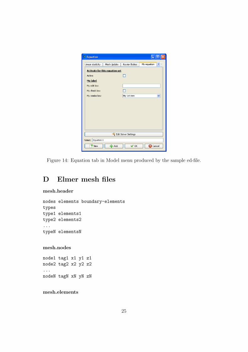
Figure 14: Equation tab in Model menu produced by the sample ed-file.
D Elmer mesh files
mesh.header
nodes elements boundary-elements
types
type1 elements1
type2 elements2
...
typeN elementsN
mesh.nodes
node1 tag1 x1 y1 z1
node2 tag2 x2 y2 z2
...
nodeN tagN xN yN zN
mesh.elements
25
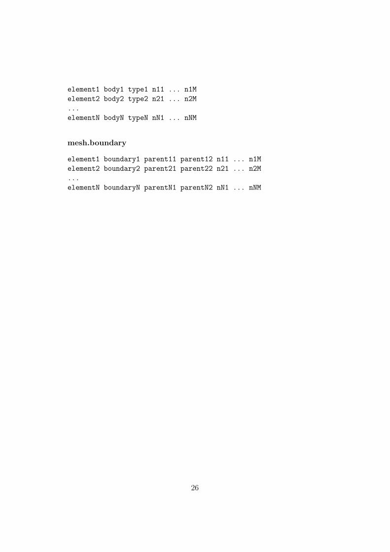
element1 body1 type1 n11 ... n1M
element2 body2 type2 n21 ... n2M
...
elementN bodyN typeN nN1 ... nNM
mesh.boundary
element1 boundary1 parent11 parent12 n11 ... n1M
element2 boundary2 parent21 parent22 n21 ... n2M
...
elementN boundaryN parentN1 parentN2 nN1 ... nNM
26

E Adding menu entries to ElmerGUI
As ElmerGUI is based on Qt4, it should be relatively easy to customize themenus and dialog windows. A new menu item, for example, is added asfollows.
First, we declare the menu action and a private slot in src/mainwindow.h:
private slots:
...
void mySlot();
...
private:
...
QAction *myAct;
...
Then, in src/mainwindow.cpp, we actually create the action, connect anappropriate signal from the action to the slot, and add the action in a menu:
void MainWindow::createActions()
{
...
myAct = new QAction(tr("*** My menu entry ***"), this);
connect(myAct, SIGNAL(triggered()), this, SLOT(mySlot()));
...
}
and
void MainWindow::createMenus()
{
...
meshMenu->addSeparator();
meshMenu->addAction(myAct);
...
}
It finally remains to define the slot to which the triggering signal is con-nected. All processing related to the action should be done here:
void MainWindow::mySlot()
{
cout << "Here we go!" << endl;
}
27
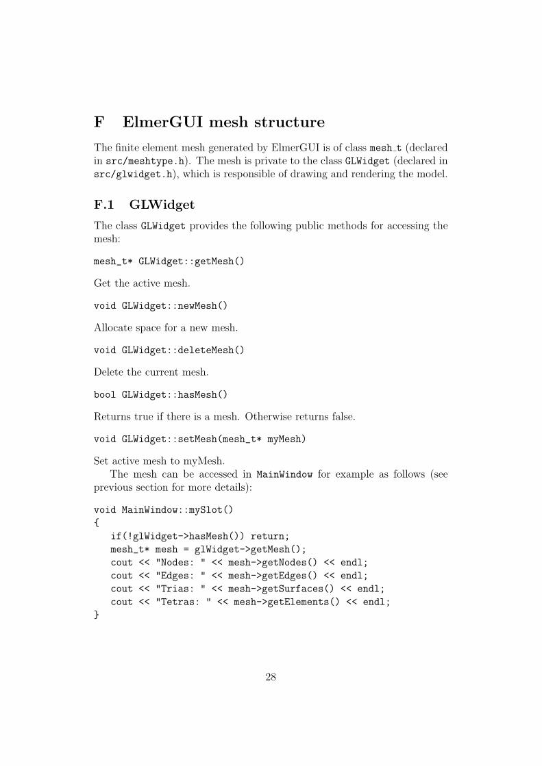
F ElmerGUI mesh structure
The finite element mesh generated by ElmerGUI is of class mesh t (declaredin src/meshtype.h). The mesh is private to the class GLWidget (declared insrc/glwidget.h), which is responsible of drawing and rendering the model.
F.1 GLWidget
The class GLWidget provides the following public methods for accessing themesh:
mesh_t* GLWidget::getMesh()
Get the active mesh.
void GLWidget::newMesh()
Allocate space for a new mesh.
void GLWidget::deleteMesh()
Delete the current mesh.
bool GLWidget::hasMesh()
Returns true if there is a mesh. Otherwise returns false.
void GLWidget::setMesh(mesh_t* myMesh)
Set active mesh to myMesh.The mesh can be accessed in MainWindow for example as follows (see
previous section for more details):
void MainWindow::mySlot()
{
if(!glWidget->hasMesh()) return;
mesh_t* mesh = glWidget->getMesh();
cout << "Nodes: " << mesh->getNodes() << endl;
cout << "Edges: " << mesh->getEdges() << endl;
cout << "Trias: " << mesh->getSurfaces() << endl;
cout << "Tetras: " << mesh->getElements() << endl;
}
28
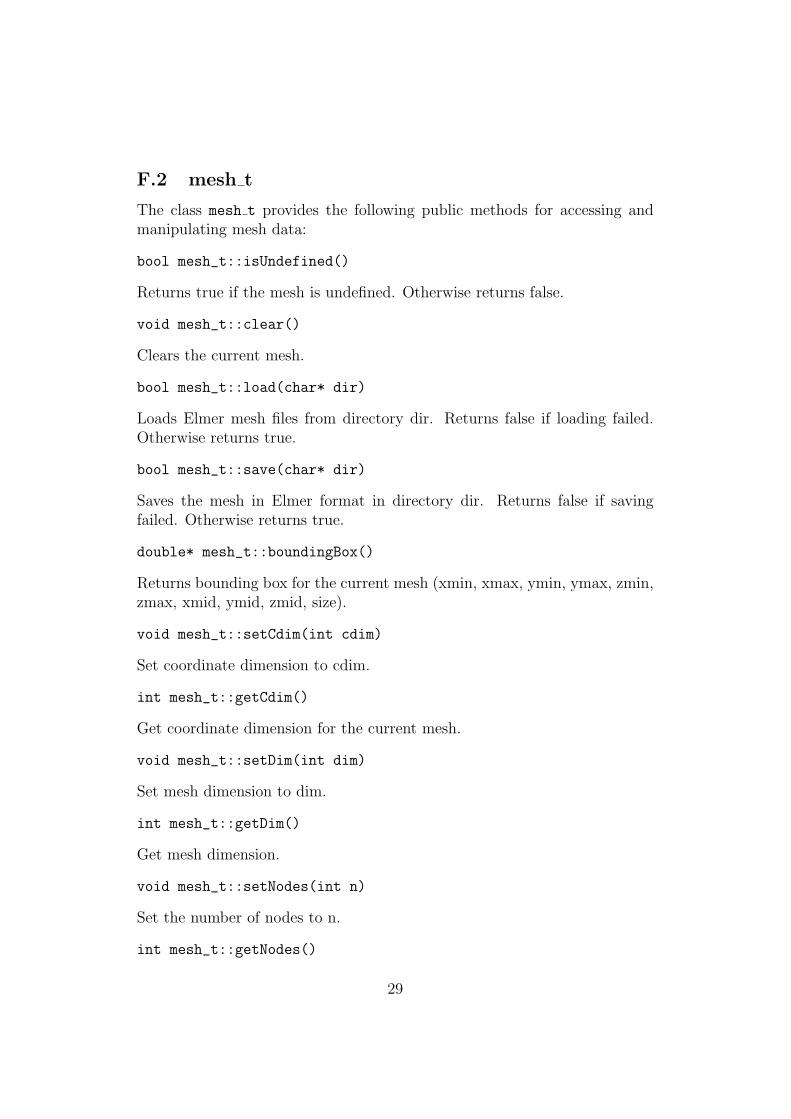
F.2 mesh t
The class mesh t provides the following public methods for accessing andmanipulating mesh data:
bool mesh_t::isUndefined()
Returns true if the mesh is undefined. Otherwise returns false.
void mesh_t::clear()
Clears the current mesh.
bool mesh_t::load(char* dir)
Loads Elmer mesh files from directory dir. Returns false if loading failed.Otherwise returns true.
bool mesh_t::save(char* dir)
Saves the mesh in Elmer format in directory dir. Returns false if savingfailed. Otherwise returns true.
double* mesh_t::boundingBox()
Returns bounding box for the current mesh (xmin, xmax, ymin, ymax, zmin,zmax, xmid, ymid, zmid, size).
void mesh_t::setCdim(int cdim)
Set coordinate dimension to cdim.
int mesh_t::getCdim()
Get coordinate dimension for the current mesh.
void mesh_t::setDim(int dim)
Set mesh dimension to dim.
int mesh_t::getDim()
Get mesh dimension.
void mesh_t::setNodes(int n)
Set the number of nodes to n.
int mesh_t::getNodes()
29
Get the number of nodes.
void mesh_t::setPoints(int n)
Set the number of point elements to n.
int mesh_t::getPoints()
Get the number of point elements.
void mesh_t::setEdges(int n)
Set the number of edge elements to n.
int mesh_t::getEdges()
Get the number of edge elements.
void mesh_t::setSurfaces(int n)
Set the number of surface elements to n.
int mesh_t::getSurfaces()
Get the number of surface elements.
void mesh_t::setElements(int n)
Set the number of volume elements to n.
int mesh_t::getElements()
Get the number of volume elements.
node_t* mesh_t::getNode(int n)
Get node n.
void mesh_t::setNodeArray(node_t* nodeArray)
Set node array point to nodeArray. Useful, if the user wants to take care ofmemory allocation by him/her self.
void mesh_t::newNodeArray(int n)
Allocate memory for n nodes.
void mesh:t::deleteNodeArray()
Delete current node array.
30
point_t* mesh_t::getPoint(int n)
Get point element n.
void mesh_t::setPointArray(point_t* pointArray)
Set point element array point to pointArray. Useful, if the user wants to takecare of memory allocation by him/her self.
void mesh_t::newPointArray(int n)
Allocate memory for n point elements.
void mesh_t::deletePointArray()
Delete current point element array.
edge_t* mesh_t::getEdge(int n)
Get edge element n.
void mesh_t::setEdgeArray(edge_t* edgeArray)
Set edge element array point to edgeArray. Useful, if the user wants to takecare of memory allocation by him/her self.
void mesh_t::newEdgeArray(int n)
Allocate memory for n edge elements.
void mesh_t::deleteEdgeArray()
Delete current edge elemet array.
surface_t* mesh_t::getSurface(int n)
Get surface element n.
void mesh_t::setSurfaceArray(surface_t* surfaceArray)
Set surface element array point to surfaceArray. Useful, if the user wants totake care of memory allocation by him/her self.
void mesh_t::newSurfaceArray(int n);
Allocate memory for n surface elements.
void mesh_t::deleteSurfaceArray()
31

Delete surface element array.
element_t* mesh_t::getElement(int n)
Get volume element n.
void mesh_t::setElementArray(element_t* elementArray)
Set volume element array point to elementArray. Useful, if the user wantsto take care of memory allocation by him/her self.
void mesh_t::newElementArray(int n)
Allocate memory for n volume elements.
void mesh_t::deleteElementArray()
Delete current volume element array.
F.3 node t
The class node t has been declared in src/meshtypes.h. It provides thefollowing public methods for accessing node data:
void node_t::setX(int n, double x)
Set component n of the position vector to x.
double node_t::getX(int n)
Get component n of the position vector.
void node_t::setXvec(double* v)
Set the position vector to v.
double* node_t::getXvec()
Get the position vector.
void node_t::setIndex(int n)
Set the index of the node to n.
int node_t::getIndex()
Get the index of the node.
32
F.4 Base element class element t
The class element t provides the following methods for accessing elementdata:
void element_t::setNature(int n)
Set element nature to n (either PDE UNKNOWN, PDE BOUNDARY, orPDE BULK).
int element_t::getNature()
Get the element nature.
void element_t::setCode(int n)
Set element code to n (202 = two noded line, 303 = three noded triangle, ...)
int element_t::getCode()
Get the element code.
void element_t::setNodes(int n)
Set the number of nodes to n.
int element_t::getNodes()
Get the number of nodes.
void element_t::setIndex(int n)
Set element index to n.
int element_t::getIndex()
Get the element index.
void element_t::setSelected(int n)
Set the selection state (1=selected, 0=unselected).
int element_t::getSelected()
Returns 1 if element is selected. Otherwise returns 0.
int element_t::getNodeIndex(int n)
Get the index of node n.
33

void element_t::setNodeIndex(int m, int n)
Set the index of node m to n.
int* element_t::getNodeIndexes()
Get the indexes of all nodes.
void element_t::newNodeIndexes(int n)
Allocate space for n node indexes.
void element_t::deleteNodeIndexes()
Delete all node indexes.
F.5 Point element class point t
The class point t inherits all public members from class element t. In addi-tion to this, it provides the following methods for accessing and manipulatingpoint element data:
void setSharp(bool b);
Mark the point element “sharp” (b=true) or not (b=false).
bool isSharp();
Returns true if the point element is “sharp”. Otherwise returns false.
void setEdges(int n);
Set the number of edges elements connected to the point to n.
int getEdges();
Get the number of edge elements connected to the point.
void setEdgeIndex(int m, int n);
Set the index of m’th edge element to n.
int getEdgeIndex(int n);
Get the index of n’th connected edge element.
void newEdgeIndexes(int n);
Allocate space for n edge element indexes.
void deleteEdgeIndexes();
Delete all edge element indexes.
34
F.6 Edge element class edge t
The class edge t inherits all public methods from element t. It also providesthe following methods for accessing and manipulating edge element data:
void edge_t::setSharp(bool b)
Mark the edge sharp (b=true) or not (b=false).
bool edge_t::isSharp()
Returns true if the edge is sharp.
void edge_t::setPoints(int n)
Set the number of point elements connected to the edge to n.
int edge_t::getPoints()
Get the number of point elements connected to the edge.
void edge_t::setPointIndex(int m, int n)
Set the index of point element m to n.
int edge_t::getPointIndex(int n)
Get the index of point element n.
void edge_t::newPointIndexes(int n)
Allocate space for n point element indexes.
void edge_t::deletePointIndexes()
Delete all point element indexes.
void edge_t::setSurfaces(int n)
Set the number of surface elements connected to the edge to n.
int edge_t::getSurfaces()
Get the number of surface elements connected to the edge.
void edge_t::setSurfaceIndex(int m, int n)
Set the index of surface element m to n.
int edge_t::getSurfaceIndex(int n)
Get the index of m’th surface element connected to the edge.
void edge_t::newSurfaceIndexes(int n)
Allocate space for n surface element indexes.
void edge_t::deleteSurfaceIndexes()
Delete all surface element indexes.
35
F.7 Surface element class surface t
Finally, the class surface t provides the following public methods for access-ing and manipulating surface element data, besides of those inherited fromthe base element class element t:
void surface\_t::setEdges(int n)
Set the number of edge elements connected to the surface to n.
int surface\_t::getEdges()
Get the number of edge elements connected to the surface element.
void surface\_t::setEdgeIndex(int m, int n)
Set the inde of m’th edge element to n.
int surface\_t::getEdgeIndex(int n)
Get the index of n’th edge element connected to the surface element.
void surface\_t::newEdgeIndexes(int n)
Allocate space for n edge element indexes.
void surface\_t::deleteEdgeIndexes()
Delete all edge element indexes.
void surface\_t::setElements(int n)
Set the number of volume elements connected to the surface element to n.
int surface\_t::getElements()
Get the number of volume elements connected to the surface element.
void surface\_t::setElementIndex(int m, int n)
Set the index of m’th volume element to n.
int surface\_t::getElementIndex(int n)
Get the index of n’th volume element connected to the surface.
void surface\_t::newElementIndexes(int n)
Allocate space for n volume element indexes.
36
void surface\_t::deleteElementIndexes()
Delete all volume element indexes.
void surface\_t::setNormalVec(double* v)
Set the normal vector to the surface element.
double* surface\_t::getNormalVec()
Get the normal vector for the surface element.
double surface\_t::getNormal(int n)
Get component n of the normal vector.
void surface\_t::setNormal(int n, double x)
Set component n of the normal to x.
void surface\_t::setVertexNormalVec(int n, double* v)
Set the normal vector for vertex n to v.
void surface\_t::addVertexNormalVec(int m, double* v)
Add vector v to the normal in vertex n.
void surface\_t::subVertexNormalVec(int m, double* v)
Subtract vector v from the normal in vertex n.
double* surface\_t::getVertexNormalVec(int n)
Get the normal vector in vertex n.
37