
ELM325 J1708 Interpreter - Elm Electronics
31
ELM325 Elm Electronics – Circuits for the Hobbyist www.elmelectronics.com J1708 Interpreter With the advent of electronic engine controls, many vehicles also adopted some form of diagnostic tools to help monitor their operation. As more modules began to be used in vehicles, there was also a need for the devices to share information rather than each independently obtain this from separate sensors. In the 1980’s, the SAE J1708 standard was created to provide a specification for a common data bus to be used in heavy duty vehicles. It used RS485 wiring (already proven to be reliable in noisy environments), and a UART-based low speed data format. The SAE J1587 standard followed a few years later to describe the mechanism by which messages and data should be sent between vehicle modules. The ELM325 allows a PC or similar device to be used to monitor and query devices on a J1708 data bus, using simple commands that can be sent from almost any terminal program. It is able to work with either the J1587 or the J1922 data formats. • Supports both SAE J1587 and J1922 • High speed RS232 interface • Works with standard RS485 transceivers • Fully configurable with AT commands • Wide operating voltage range (1.8 to 5.5V) • Low power CMOS design • Diagnostic trouble code readers • Heavy duty vehicle scan tools • Teaching aids • ECU Simulators Description Applications Features 1 of 31 ELM325DSA Block Diagram Connection Diagram PDIP and SOIC (top view) VDD VSS RO InvDE XT1 XT2 DE J Tx LED RS Rx LED J Rx LED 1 2 3 14 13 12 11 4 5 6 10 9 8 7 RS232 Tx RE RS Tx LED RS232 Rx 2 3 XT1 XT2 5 6 Timing and Control J1587/1922 Interpreter J1708 Interface RO 11 13 RE 4 DE 12 RS232 Tx RS232 Rx InvDE J Tx LED 10 J Rx LED 9 3.58 MHz RS232 Interface 7 RS Rx LED RS Tx LED 8
Transcript of ELM325 J1708 Interpreter - Elm Electronics

ELM325
Elm Electronics – Circuits for the Hobbyistwww.elmelectronics.com
J1708 Interpreter
With the advent of electronic engine controls,many vehicles also adopted some form of diagnostictools to help monitor their operation. As moremodules began to be used in vehicles, there wasalso a need for the devices to share informationrather than each independently obtain this fromseparate sensors.
In the 1980’s, the SAE J1708 standard wascreated to provide a specification for a common databus to be used in heavy duty vehicles. It usedRS485 wiring (already proven to be reliable in noisyenvironments), and a UART-based low speed dataformat. The SAE J1587 standard followed a fewyears later to describe the mechanism by whichmessages and data should be sent between vehiclemodules.
The ELM325 allows a PC or similar device to beused to monitor and query devices on a J1708 databus, using simple commands that can be sent fromalmost any terminal program. It is able to work witheither the J1587 or the J1922 data formats.
• Supports both SAE J1587 and J1922
• High speed RS232 interface
• Works with standard RS485 transceivers
• Fully configurable with AT commands
• Wide operating voltage range (1.8 to 5.5V)
• Low power CMOS design
• Diagnostic trouble code readers
• Heavy duty vehicle scan tools
• Teaching aids
• ECU Simulators
Description
Applications
Features
1 of 31ELM325DSA
Block Diagram
Connection DiagramPDIP and SOIC
(top view)
VDD VSS
RO
InvDE
XT1
XT2
DE
J Tx LED
RS Rx LED
J Rx LED
1
2
3
14
13
12
114
5
6
10
9
87
RS232 Tx
RE
RS Tx LED
RS232 Rx
2 3XT1 XT2
5
6
Timing andControl
J1587/1922Interpreter
J1708Interface
RO
11
13
RE
4
DE
12
RS232 Tx
RS232 Rx
InvDE
J Tx LED10
J Rx LED9
3.58 MHz
RS232Interface
7RS Rx LED
RS Tx LED 8

ELM325
Elm Electronics – Circuits for the Hobbyistwww.elmelectronics.com
2 of 31ELM325DSA
Electrical Information Copyright and Disclaimer.............................................................2
Pin Descriptions........................................................................... 3
Absolute Maximum Ratings......................................................... 4
Electrical Characteristics..............................................................4
Using the ELM325 Overview...................................................................................... 5
Communicating with the ELM325................................................ 5
AT Commands............................................................................. 7
AT Command Summary...............................................................7
AT Command Descriptions.......................................................... 8
Sending AT Commands............................................................. 11
J1587 Commands...................................................................... 12
Listening to a Vehicle.................................................................13
Receive Filtering........................................................................ 14
Getting Trouble Codes............................................................... 15
Making Requests....................................................................... 16
Automatic Receive Filters.......................................................... 17
Setting the MID.......................................................................... 18
Multiline Responses................................................................... 18
Setting the Timeout....................................................................20
About J1922...............................................................................21
Restoring Order..........................................................................21
Design Discussions Microprocessor Interfaces..........................................................22
Example Applications.................................................................23
Tester Connectors......................................................................27
Misc Error Messages and Alerts.........................................................28
Outline Diagrams....................................................................... 29
Ordering Information.................................................................. 29
Index.......................................................................................... 30
Contents
All rights reserved. Copyright 2012 by Elm Electronics Inc.Every effort is made to verify the accuracy of information provided in this document, but no representation or warranty can be given and no liability assumed by Elm Electronics with respect to the accuracy and/or use of any products or information described in this document. Elm Electronics will not be responsible for any patent infringements arising from the use of these products or information, and does not authorize or warrant the use of any Elm Electronics product in life support devices and/or systems. Elm Electronics reserves the right to make changes to the device(s) described in this document in order to improve reliability, function, or design.

ELM325
Elm Electronics – Circuits for the Hobbyistwww.elmelectronics.com
Pin Descriptions
3 of 31
VDD (pin 1)
This pin is the positive supply pin, and should alwaysbe the most positive point in the circuit. Internalcircuitry connected to this pin is used to providepower on reset of the microprocessor, so an externalreset signal is not required. Refer to the ElectricalCharacteristics section for further information.
XT1 (pin 2) and XT2 (pin 3)
A 3.579545 MHz oscillator crystal (often knownsimply as a ‘3.58 MHz’ crystal) is to be connectedbetween these two pins. Loading capacitors asrequired by the crystal (typically 27pF) also need tobe connected from each of these pins to circuitcommon (Vss). A crystal is preferred, but you mayalso use a ceramic resonator.
Note that this device has not been configured foroperation with an external oscillator, and it expects acrystal or resonator to be connected between thesepins. Use of an external clock source is notrecommended.
InvDE (pin 4)
This input is used to invert the output at the DE pin.This allows the ELM325 to be connected to a varietyof RS485 interface circuits without the need for anexternal inverter.
Normally, the InvDE pin is connected to a high (VDD)level. This causes the DE output (pin 11) to be at alow level during idle, and go to a high level for thestart bit (ie. when active). This is required for mostRS485 interface ICs such as the 75176, DS485,LTC485, ADM485, MAX485, and SN65HVD3080E.If you are using a device that requires an active lowDE output (such as the DS36277), then connect theInvDE pin to a low level.
RS232 Rx (pin 5)
This is the RS232 (serial) data receive input. Thesignal level is compatible with most interface ICs(when at idle, the level should be high), but can beused with other interfaces as well, since the inputhas Schmitt trigger input wave shaping.
RS232 Tx (pin 6)
This is the RS232 (serial) data transmit output. Thesignal level is compatible with most interface ICs (theoutput is high when idle), and there is sufficientcurrent drive to allow interfacing using only a PNPtransistor, if desired.
RS Rx LED (pin 7), RS Tx LED (pin 8),
J Rx LED (pin 9) and J Tx LED (pin 10)
These four pins normally output a high level, and aredriven low when the ELM325 is transmitting orreceiving data. The internal circuitry is suitable fordirectly driving most LEDs through current limitingresistors, or interfacing to other logic circuits. Whenusing lower VDD levels, the LED should be chosen sothat the forward voltage drop is not more than thesupply level. If unused, these pins should be leftopen-circuited.
DE (pin 11)
This is the J1708 transmit data output, which shouldbe connected to the DE pin on an RS485 transceiverintegrated circuit. The polarity of this signal may bechanged by changing the level on the InvDE pin.
RE (pin 12)
This is a receiver enable output, which may be usedto enable or disable the RS485 receiver. For somecircuits this might result in a substantial reduction incurrent, if the receiver is not being used.
This pin is set to a low level on powerup, or ELM325reset. The level may be controlled with the AT RE0and RE1 commands. If unused, this pin should beleft open-circuited.
RO (pin 13)
This is the J1708 receive data input, and should beconnected to the receive output (RO) pin of theRS485 transceiver IC. This is a standard CMOSinput that accepts TTL level signals.
VSS (pin 14)
Circuit common must be connected to this pin.
ELM325DSA

Elm Electronics – Circuits for the Hobbyistwww.elmelectronics.com
Absolute Maximum Ratings
Storage Temperature....................... -65°C to +150°C
Ambient Temperature withPower Applied....................................-40°C to +85°C
Voltage on VDD with respect to VSS..... -0.3V to +6.5V
Voltage on any other pin withrespect to VSS........................... -0.3V to (VDD + 0.3V)
Note:
These values are given as a design guideline only. The ability to operate to these levels is neither inferred nor recommended, and stresses beyond those listed here will likely damage the device.
4 of 31ELM325DSA
ELM325
Electrical Characteristics
Notes:1. This integrated circuit is based on Microchip Technology Inc.’s PIC16F1823 device. For more detailed
device specifications, and possibly clarification of those given, please refer to the Microchip documentation(available at http://www.microchip.com/).
2. This spec must be met in order to ensure that a correct power on reset occurs. It is quite easily achievedusing most common types of supplies, but may be violated if one uses a slowly varying supply voltage, asmay be obtained through direct connection to solar cells or some charge pump circuits.
3. ELM325 device only – does not include any load currents
All values are for operation at 25°C and a 5V supply, unless otherwise noted. For further information, refer to note 1 below.
Characteristic Minimum Typical Maximum ConditionsUnits
Supply voltage, VDD 1.8 5.0 5.5 V
VDD rate of rise 0.05 V/ms
Average current, IDD 1.2 mA
8.0 mAOutput low current
Output high current
see note 2
VOUT = 0.6V max
3.5
3.0
J1708 Baud Rate
RS232 Baud Rate
Reset time 900 msec
bps
bps57600
9600
VDD = 5.0V
0.75 msec
see note 3
VDD = 3.3V
VDD = 5.0V
VDD = 3.3V
6.0 mA
mA VOUT = 4.3V min
mA VOUT = 2.6V min
VOUT = 0.6V max
measured from the end of the command to the start of the ID message (ELM325 v1.0)
2.0
AT Z
AT WS

5 of 31
ELM325
ELM325DSA Elm Electronics – Circuits for the Hobbyistwww.elmelectronics.com
Communicating with the ELM325
The ELM325 expects to communicate with thecontrolling device through an RS232 serial connection.Although most modern devices do not usually providea serial connection such as this, there are severalways in which a ‘virtual serial port’ can be created. Themost common devices are USB to RS232 adapters,but there are several others such as Wi-Fi modules,ethernet devices, or Bluetooth to serial adapters.
No matter how you physically connect to theELM325, you will need a way to send and receivedata. The simplest method is to use one of the many‘terminal’ programs that are available (HyperTerminal,ZTerm, etc.), to allow typing the characters directlyfrom your keyboard.
To use a terminal program, you will need to adjustseveral settings. First, ensure that your software is setto use the proper ‘COM’ port, and that you havechosen the proper data rate – the ELM325 can onlycommunicate at 57600 bps. If you select the wrong‘COM’ port, you will not be able to send or receive anydata. If you select the wrong data rate, but the right‘COM’ port, the information that you send and receivewill be unreadable by you or the ELM325. Don’t forgetto also set your connection for 8 data bits, no paritybits, and 1 stop bit, and to set it for the proper ‘lineend’ mode. All of the responses from the ELM325 areterminated with a single carriage return character and,optionally, a linefeed character (depending on yoursettings).
Properly connected and powered, the ELM325 willenergize the four LED outputs in sequence (as a ‘lamptest’) and will then send the message:
ELM325 v1.0
>
In addition to identifying the version of this IC,receiving this string is a good way to confirm that thecomputer connections and terminal software settings
are correct (however, at this point no communicationshave taken place with the vehicle, so the state of thatconnection is still unknown).
The ‘>’ character that is shown on the second lineis the ELM325’s prompt character. It indicates that thedevice is in the idle state, ready to receive characterson the RS232 port. If you did not see the identificationstring, try resetting the IC again with the AT Z (reset)command. Simply type the letters A T and Z (spacesare optional), then press the return key:
>AT Z
That should cause the LEDs to flash again, andthe identification string to be printed. If you only seestrange looking characters, then check your baud rate– you have likely set it incorrectly.
Characters sent from the computer can either beintended for the ELM325’s internal use, or forreformatting and passing on to the vehicle. TheELM325 can quickly determine where the receivedcharacters are to be directed by monitoring thecontents of the message. Commands that areintended for the ELM325’s internal use will begin withthe characters ‘AT’, while messages for the vehicle areonly allowed to contain the ASCII codes forhexadecimal digits (0 to 9 and A to F).
Whether it is an ‘AT’ type internal command or ahex string for the J1708 bus, all messages to theELM325 must be terminated with a carriage returncharacter (hex ‘0D’) before it will be acted upon. Theone exception is when an incomplete string is sent andno carriage return appears. In this case, an internaltimer will automatically abort the incomplete messageafter about 20 seconds, and the ELM325 will print asingle question mark (‘?’) to show that the input wasnot understood (and was not acted upon).
Messages that are not understood by the ELM325(syntax errors) will always be signalled by a single
Overview
The following describes how to use the ELM325 toobtain information from your vehicle.
We begin by discussing just how to ‘talk’ to the ICusing a PC, then explain how to change options usingthe ‘AT’ commands, and finally we show how tocommunicate with a vehicle. For the more advancedexperimenters, there are also sections on how to usesome of the other features of this product as well.
Using the ELM325 is not as daunting as it firstseems. Many users may never need to issue an ‘AT’command, adjust timeouts, or change the MID. Forthose that do want to make changes, all that isrequired is a PC or smart device with a terminalprogram (such as HyperTerminal or ZTerm), and alittle knowledge…

Communicating with the ELM325 (continued)
question mark. These include incomplete messages,incorrect AT commands, or invalid hexadecimal digitstrings, but are not an indication of whether or not themessage was understood by the vehicle. One mustkeep in mind that the ELM325 is a protocol interpreterthat makes no attempt to assess the content ofmessages for validity – it only ensures thathexadecimal digits were received, combined intobytes, then sent out the J1708 port, and it does notknow if a message sent to the vehicle was appropriateor not.
While processing J1708 messages, the ELM325will continually monitor for an RS232 characterreceived. If it sees one, this will interrupt the IC, quicklyreturning control to the user. Since the time to respondvaries with what the ELM325 was doing at the time,software should always wait for the prompt character(‘>’ or hex 3E) to be received, before beginning tosend the next command.
Finally, it should be noted that the ELM325 is notcase-sensitive, so the commands ‘ATZ’, ‘atz’, and
‘AtZ’ are all exactly the same to the ELM325. Allcommands may be entered as you prefer, as no onemethod is faster or better. The ELM325 also ignoresspace characters and all control characters (tab, etc.),so they can be inserted anywhere in the input toimprove readability.
One other feature of the ELM325 is the ability torepeat the last command when only a single carriagereturn character is received. This may be convenient ifyou have sent a command and wish to repeat it inorder to obtain updates. If you simply send a carriagereturn, then you do not have to resend the entirecommand. The memory buffer only remembers oneprevious command though – there is no provision inthe current ELM325 to provide storage for more.
6 of 31
ELM325
ELM325DSA Elm Electronics – Circuits for the Hobbyistwww.elmelectronics.com
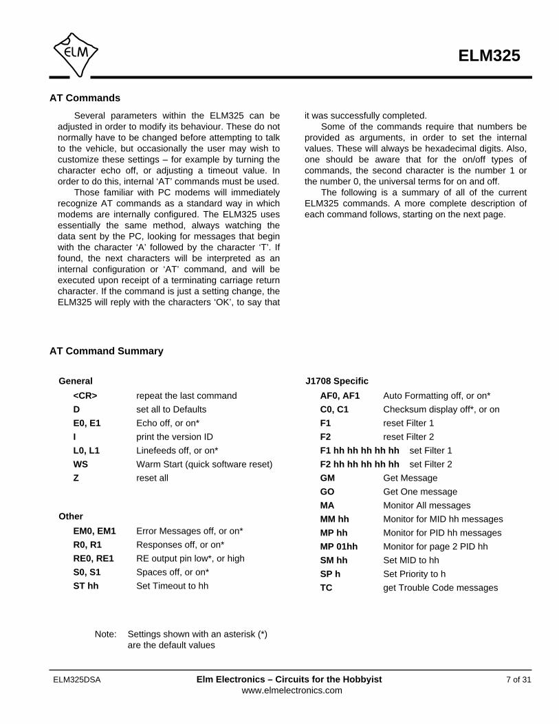
Several parameters within the ELM325 can beadjusted in order to modify its behaviour. These do notnormally have to be changed before attempting to talkto the vehicle, but occasionally the user may wish tocustomize these settings – for example by turning thecharacter echo off, or adjusting a timeout value. Inorder to do this, internal ‘AT’ commands must be used.
Those familiar with PC modems will immediatelyrecognize AT commands as a standard way in whichmodems are internally configured. The ELM325 usesessentially the same method, always watching thedata sent by the PC, looking for messages that beginwith the character ‘A’ followed by the character ‘T’. Iffound, the next characters will be interpreted as aninternal configuration or ‘AT’ command, and will beexecuted upon receipt of a terminating carriage returncharacter. If the command is just a setting change, theELM325 will reply with the characters ‘OK’, to say that
it was successfully completed.Some of the commands require that numbers be
provided as arguments, in order to set the internalvalues. These will always be hexadecimal digits. Also,one should be aware that for the on/off types ofcommands, the second character is the number 1 orthe number 0, the universal terms for on and off.
The following is a summary of all of the currentELM325 commands. A more complete description ofeach command follows, starting on the next page.
7 of 31
ELM325
ELM325DSA Elm Electronics – Circuits for the Hobbyistwww.elmelectronics.com
AT Command Summary
AT Commands
General
<CR> repeat the last command
D set all to Defaults
E0, E1 Echo off, or on*
I print the version ID
L0, L1 Linefeeds off, or on*
WS Warm Start (quick software reset)
Z reset all
Other
EM0, EM1 Error Messages off, or on*
R0, R1 Responses off, or on*
RE0, RE1 RE output pin low*, or high
S0, S1 Spaces off, or on*
ST hh Set Timeout to hh
J1708 Specific
AF0, AF1 Auto Formatting off, or on*
C0, C1 Checksum display off*, or on
F1 reset Filter 1
F2 reset Filter 2
F1 hh hh hh hh hh set Filter 1
F2 hh hh hh hh hh set Filter 2
GM Get Message
GO Get One message
MA Monitor All messages
MM hh Monitor for MID hh messages
MP hh Monitor for PID hh messages
MP 01hh Monitor for page 2 PID hh
SM hh Set MID to hh
SP h Set Priority to h
TC get Trouble Code messages
Note: Settings shown with an asterisk (*)are the default values

8 of 31
ELM325
ELM325DSA Elm Electronics – Circuits for the Hobbyistwww.elmelectronics.com
AT Command Descriptions
<CR> [ repeat the last command ]
Sending a single carriage return character causesthe ELM325 to repeat the last command that itperformed. This helps if you wish to repeat a requestseveral times to obtain updates for a monitored value,for example.
AF0 and AF1 [ Auto Formatting off or on* ]
All messages must start with the sender’s address(the MID) and end with a checksum. If automaticformatting is on (it is by default), the ELM325 will addthese to every message for you, so that you only needto provide the data bytes that you wish to send. Ifautomatic formatting is off, you must provide all bytes,including the MID and the checksum.
Automatic (ie ‘auto’) formatting also provides helpwhen making requests for a PID. If you provide onedata byte, or two data bytes with the first being 01, theELM325 assumes that you wish to make a PIDrequest. It will add the MID, the request PID,checksum, etc. for you, set the filters if you haven’t,and send the request. If the auto formatting is off, allbytes that you provide are sent without modification ofany kind (but the ELM325 still attempts to set filters foryou, if you have not set any).
One final issue to note is that the ELM325’sinternal J1708 buffer is 21 bytes long. This means thatyou may actually send a 23 byte message if formattingis on (MID + 21 bytes in buffer + checksum), but if theauto formatting is off, the total length of the messagemust be 21 bytes or less (as the entire message istaken from the buffer). It also means that if you try toprovide 21 data bytes for a message, plus a messagecount nibble, you will get an error (as you have over-filled the internal buffer). This is generally of noconcern if you are implementing the SAE J1587protocol, but may be an issue if you are trying to sendsome special SAE J1922 messages.
C0 and C1 [ Checksum display off* or on ]
These commands are used to make the received
checksum byte visible or not. Usually, it is preferredthat the byte not be shown, so the ELM325 hides it bydefault. If you wish to see the byte printed with everymessage, simply send AT C1.
D [ set all to Defaults ]
This command is used to set the options to theirdefault (or factory) settings, as when power is firstapplied. Any settings that you had made for a customMID, for filters, for message formatting, or timersettings will be restored to their default values.
E0 and E1 [ Echo off or on* ]
These commands control whether or not thecharacters received on the RS232 port are echoed(retransmitted) back to the host computer. Characterecho can be used to confirm that the characters sentto the ELM325 were received correctly. The default isE1 (or echo on).
EM0 and EM1 [ Error Messages off or on* ]
If a message is received and there is a problemwith it, the ELM325 will add an error description to thereceived line. An arrow (‘<‘) that points to the messageis printed first, then either PROT ERROR, RX ERROR,or DATA ERROR is printed to describe the problem.You may find that the description is of little use to youin your application, and wish to only see the ‘arrow’. Ifyou set AT EM0, the ELM325 will do that for you.
F1 [ reset Filter 1 ]
If you have set message receive filter F1 and wishto disable that setting, simply send AT F1. TheELM325 will discard any setting that you had made.
F2 [ reset Filter 2 ]
If you have set message receive filter F2 and wishto disable that setting, simply send AT F2. TheELM325 will discard any setting that you had made.
The following describes each AT Command that thecurrent version of the ELM325 supports, in somedetail. Many of these commands are also describedfurther in other sections:

9 of 31
ELM325
ELM325DSA Elm Electronics – Circuits for the Hobbyistwww.elmelectronics.com
AT Command Descriptions (continued)
F1 hh hh hh hh hh [ set Filter 1 to… ]
Filter F1 can be used to selectively receive onlythe messages that contain matching bytes in the firstfive byte positions. Simply set the values for the fivebytes (ten nibbles) with this command and theELM325 will make the internal adjustments for you. Ifthere is a nibble that can have any value, then use theletter ‘X’ to define it. See the Receive Filtering sectionfor more details.
F2 hh hh hh hh hh [ set Filter 2 to… ]
Filter F2 can be used to selectively receive onlythe messages that contain matching bytes in the firstfive byte positions. Simply set the values for the fivebytes (ten nibbles) with this command and theELM325 will make the internal adjustments for you. Ifthere is a nibble that can have any value, then use theletter ‘X’ to define it. See the Receive Filtering sectionfor more details.
GM [ Get Message ]
Occasionally, you may wish to set the receive filterfor a particular message and ‘get’ it from the datastream. The AT GM command may be used to do so.
This command is very similar to AT MA with theF1/F2 filters set, except that it respects the AT STtimeout value. That is, if no message is received in theST time, the ELM325 will return with a NO DATAmessage, and if multiple messages are received withinthat time, they will all be displayed. Note that F1 and/orF2 must be set prior to using AT GM.
GO [ Get One message ]
This command performs exactly as the AT GMcommand, except that it only gets one response andthen returns immediately to the prompt.
I [ Identify yourself ]
Issuing this command causes the chip to identifyitself, by printing the startup product ID string (currently‘ELM325 v1.0’). Software can use this to determineexactly which integrated circuit it is talking to, withouthaving to reset the IC.
L0 and L1 [ Linefeeds off or on* ]
This option controls the sending of linefeedcharacters (0x0A) after each carriage return character
(0x0D). Users will generally wish to have this option onif using a terminal program, but off if using a customcomputer interface (as the extra characters transmittedwill only serve to slow the communications down). Thedefault setting is L1 (linefeeds on).
MA [ Monitor All messages ]
This command places the ELM325 into a busmonitoring mode, in which it continually monitors for(and displays) all messages that it sees. If the F1 andF2 filters have not been set, then all messages on theJ1708 bus will be displayed.
Often, it is not desirable to display everything thatis being transmitted on the system. If you wish toreduce the amount of information displayed, simply setthe F1 and/or F2 filters to the values that you wish tosee. Then, with AT MA, the ELM325 will display allmessages that meet that criteria.
MM hh [ Monitor for MID hh ]
The AT MM command is similar to the AT MAcommand except that it also filters for only messagesthat match the MID provided. That is, the AT MMcommand is effectively an extra filter that can beapplied to incoming messages.
MP hh [ Monitor for PID hh ]
The AT MP command is very similar to the AT MMcommand except that it only allows messages with theprovided PID value in the second byte position. Again,the F1 and/or F2 filters may be used to further refinethe data that is shown.
MP 01hh [ Monitor for page 2 PID hh ]
This command is identical to the previouscommand except that it filters for page 2 PIDs (that is,for PIDs of value 0100 to 01FF). Again, F1 and F2filters can also be used with this command.
As an aside, this command actually monitors for0xFF in the second byte position, and for the hh valuein the third byte position (which is the way that page 2PIDs are defined in the SAE J1587 standard).
R0 and R1 [ Responses off or on* ]
These commands control whether the ELM325 willlook for a response from the vehicle, after a messagehas been sent. If responses have been turned off (with

10 of 31
ELM325
ELM325DSA Elm Electronics – Circuits for the Hobbyistwww.elmelectronics.com
AT R0), the ELM325 will not wait for a reply from thevehicle after sending a request – it will simply say ‘OK’,and will then return immediately to wait for the nextcommand. An R0 setting will always override any‘number of responses digit’ that is provided with amessage.
R0 may be useful for sending commands blindlywhen simulating an ECU for demonstration or testpurposes. The default setting is R1, or responses on.
RE0 and RE1 [ RE output to 0* or 1 ]
This command is used to control the state of theRE output pin. After a powerup or reset, the ELM325always sets this pin to a low level. If you send AT RE1,you will change the output to a high level (ie to VDD),and AT RE0 will restore it to a low level (VSS).
While this pin was intended for use with RS485transceiver ‘receive enable’ inputs, it does not need tobe used in that way. This control pin functionsindependently of any internal circuitry so can be usedfor many other functions, such as disabling peripheralsor blinking an LED.
S0 and S1 [ printing of Spaces off or on* ]
This command controls whether or not spacecharacters are inserted in the message response.
The ELM325 normally formats messageresponses as a series of two nibbles followed by aspace (0x20) character. If you wish to reduce theamount of received data and your PC’s processingtime, you may wish to turn spaces off. By default,spaces are on (S1), and space characters are insertedin every response.
SM hh [ Set the MID to hh ]
The ELM325 normally assumes that you wish tosend using the MID ‘AC’ (which is decimal 172). Thisvalue has been assigned by SAE J1587 to the #1 Off-board Diagnostics unit. If you wish to change the MIDthat the ELM325 uses when sending messages,simply define it with this command. See the ‘Settingthe MID’ section for more information.
SP h [ Set the Priority to h ]
Each message that is sent by the ELM325 has apriority assigned to it. These priorities can have valuesfrom 1 (the highest) to 8 (the lowest).
The AT SP command may be used to change the
message priority, but great care must be used withthis. It is possible to preempt other more importantmessages if you change the priority, possiblyadversely affecting the operation of the vehicle. Do notadjust this parameter if you are unsure of why you aredoing so, and what affect it may have. By default, theELM325 uses a priority value of 8.
ST hh [ Set Timeout to hh ]
After sending a request, the ELM325 waits apreset time for a response before it can declare thatthere was ‘NO DATA’ received from the vehicle. Thesame timer setting is also used after a response hasbeen received, while waiting to see if any more arecoming. The AT ST command allows this timer to beadjusted, in increments of 100 msec.
The ST timer is set to 0F (15 decimal) by default,which gives a time of 1.5 seconds. Note that sendingAT ST 00 does not result in no time – it causes thedefault time to be set.
TC [ monitor for Trouble Code messages ]
This command is used to quickly monitor fortrouble codes that are being broadcast – that is, allPIDs that are equal to C2 (or decimal 194), withouthaving to set the filters.
The AT TC command uses the AT ST timer to limitthe time that it waits for a message to arrive.
WS [ Warm Start ]
This command causes the ELM325 to perform acomplete reset which is very similar to the AT Zcommand, but does not include the power on LEDtest. Users may find this a convenient way to quickly‘start over’ without having the extra delay of the AT Zcommand.
Z [ reset all ]
This command causes the chip to perform acomplete reset as if power were cycled off and then onagain. All settings are returned to their default values,and the chip will be put into the idle state, waiting forcharacters on the RS232 bus.
AT Command Descriptions (continued)
Sending AT Commands
Before learning some J1587 Commands, we willshow a few examples of how to use an AT Command.We will assume that you have built (or purchased) acircuit that is similar to that of Figure 7 in the ExampleApplications section.
Do not connect your circuit to a vehicle at thistime. Power it from a test source only (a 9V ‘transistorradio’ battery works well), and connect it to your PC asdiscussed in the Communicating with the ELM325section.
For your first command, simply reset the IC bysending AT Z. Try this a few ways (don’t forget topress enter or return after each):
>AT Z
or
>atz
or
>a T z
You should see the RS232 LEDs blink as you typeeach letter, and after you press return (or enter) youshould see all four Tx/Rx LEDs blink, in order, followedby a final blink of the RS232 Tx LED as the ELM325sends ‘ELM325 v1.0’.
Most J1708 messages are continually sent on thedata bus, at a predetermined rate. Some messagesmay be sent 10x per second, while others are only 1xper 10 seconds. This means that you may need toadjust the internal timeout setting depending on whatmessage you are attempting to receive. We will adjustthis timeout setting next.
Try this request for trouble codes:
>AT TC
After about 2 seconds, you should see a responsethat looks like:
NO DATA
>
since there is no vehicle attached, there was no datareceived.
Now, adjust the timeout to 10 seconds. If you lookat the AT command list, you will see that there is a SetTimeout command that is used for this. Timing is inincrements of 100 msec (0.1 sec), so to obtain a 10second delay, the AT ST setting should be 100. Weneed to convert the 100 to hexadecimal, however, as
all numbers handled by the ELM325 must be inhexadecimal. Converting then, 100 (= 6 x 16 + 4) is 64in hexadecimal, so we send:
>AT ST 64
Again, don’t forget to press return (or enter). Now,the timeout should be set to 10 seconds. To verify this,repeat the Trouble Codes command:
>AT TC
It should be 10 seconds before you see the NODATA response this time. To try it again, you do notneed to enter the AT TC command again, you onlyneed to press enter, and the ELM325 will repeat yourlast command (AT TC) for you.
As a final test, enter AT TC again, but before the10 seconds is up, press any key on the keyboard. Youshould see the ELM325 respond with:
STOP?
which means that it was interrupted and it thinks thatyou wish to stop. If you ever see the ‘STOP?’response, it means that the ELM325 thinks it has beeninterrupted by you.
Now, restore the AT ST time to the default value,with the Defaults command:
>AT D
You should see a response of ‘OK’ and then aprompt character on a new line, to show that theELM325 is waiting for you. In this case, you might alsohave sent AT ST 00, since that also restores thetimeout setting to its default value.
Experiment with these commands – you are notconnected to a vehicle, so can do no harm. SendingAT Commands is not difficult, they just require a littlepractice.
11 of 31
ELM325
ELM325DSA Elm Electronics – Circuits for the Hobbyistwww.elmelectronics.com

J1587 Commands
The SAE J1708 standard defines how messagesshould be sent on what is essentially an RS485 databus. The actual content of the messages are definedby the SAE J1587 standard (and the J1922 standard,too, but it is very similar). Our discussion from thispoint on will be in regard to the J1587 messages only(the ELM325 handles the rest of the conversionprocess for us).
J1587 messages always begin with a single bytecalled the Message ID, or MID. It is basically thesender’s address (they are always predefined, and notwo devices on the bus can have the same MID).
The next byte contains a Parameter IDentificationnumber, or PID. It tells you what type of information iscontained in the message. One or more data bytesfollow the PID and are the actual content of themessage being sent. Several PID/data groups can becontained in a single message as long as there are nomore than 19 bytes of data used (that is, the messagemust be 21 bytes or less in length).
If multiple groups of data are transmitted in onemessage, there needs to be a way to separate themwhen received, and the SAE J1587 standard sets outhow this is done. PIDs 00 to 7F (ie 0 to 127), alwayshave one data byte only, while PIDs 80 to BF (128 to191) have two data bytes. PIDs C0 to FD (192 to 253)can have a variable number of data bytes – the
number is always given in the first byte following thePID. The pattern repeats again for the page 2 PIDs(0100 to 017F have one byte, 0180 to 01BF have two,etc.)
PID FE (ie 254) is a special one called the datalink escape PID. The data contained within thatmessage is manufacturer specific.
Finally, PID FF (ie 255) is used to signal that allthe PIDs in that message are in page 2. That is, PIDsare always defined with one byte, modulo 256. To saythat all of the PIDs referred to in the message areactually in the range 0100 to 01FF (256 to 511), thefirst PID (ie. the second byte in the message) will beFF (255).
The final byte of a message, after all the PID andData groups, contains a checksum. This helps thereceiver to detect if errors have occurred in the datathat is received. The ELM325 does not normally showthis byte when receiving a message, but you can haveit displayed if you send the AT C1 command.
Figure 1 below shows pictorially how a J1587message is formed. If you wish to learn more aboutthe SAE J1587 standard, you may purchase a copyfrom www.sae.org.
12 of 31
ELM325
ELM325DSA Elm Electronics – Circuits for the Hobbyistwww.elmelectronics.com
Figure 1. The SAE J1587 Message Structure
MID PID Data for the PID PID Data . . . PID Data Checksum
maximum 19 bytes
more than one PID group is allowed

Listening to a Vehicle
Before we begin, it should be noted that theELM325 always uses hexadecimal numbers whencommunicating with the PC. That is, while the J1587standard may talk of engine #1 being assigned a MIDof 128, the ELM325 always uses 80 for that sameaddress. If you are not familiar with the hexadecimalnumbering system, you should review it beforeproceeding.
Listening to a vehicle with the ELM325 is exactlythe same as with the other ELM OBD ICs – simply tellthe IC that you want to monitor all data:
>AT MA
and the chip will begin displaying all the data that itsees. (If you are connected to a ‘live’ vehicle, but arenot seeing data, you may have reversed the polarity ofyour J1708 connections.) To stop the flow of data,simply press any key on the keyboard.
Perhaps this is too much data and you wish toonly see data being sent by the engine. You mayeasily monitor for only that MID, by sending:
>AT MM 80
and you should then only see data that begins withMID 80. Note that the ELM325 does not show thechecksum by default – you need to tell it to show thatbyte. For example, monitoring for MID 80 might show:
>AT MM 8080 5C 66 BE E0 2E80 B7 40 06 5C 64 BE 30 2F80 5C 64 BE 30 2Fetc.
if you wish to see the checksum byte, send AT C1then monitor for MID 80:
>AT C1OK
>AT MM 8080 5C 66 BE E0 2E F280 B7 40 06 5C 64 BE 30 2F A680 5C 64 BE 30 2F A3etc.
While other J1587 monitors tend to always showthe checksum, the ELM325 hides it by default (as itdoesn’t really help in assessing the data).
Just what is the information contained in these
messages? If you look at the first line that wasreceived (with the checksum turned off), you can breakit into components as follows:
80 5C 66 BE E0 2E
MID(engine #1)
PID 5C(% load)
PID BE(rpm)
The first byte (80) represents the engine #1 MID,while the second byte is always a PID (5C in thiscase). Since 5C is in the range from 00 to 1F, there isone data byte following the PID (the 66) before thenext PID begins. The next PID is then BE, which is inthe range 80 to BF so it should have two data bytesassociated with it (which it does).
What does this data mean? Well, 5C is equivalentto 92 in decimal. Looking up this PID in J1587, onefinds that it is for the % engine load, and each digitrepresents 1/2 %. Converting 66 to decimal gives 102,so the % engine load is 102 x 1/2% = 51%.
The second PID is BE (190 decimal), which is forengine speed, with each digit representing 1/4 rpm.Simple enough, but how do you interpret the two databytes? ie Should they be E02E or 2EE0? It turns outthat the J1587 standard uses what is known as ‘littleendian’ data representation, so the first byte that yousee is the least significant (little) one. The engine rpmdata should be interpreted as 2EE0, or 12000 decimal.With 1/4 rpm per digit, the speed is then 3000 rpm.
The other lines received (or other messages) canbe analyzed in a similar fashion. Start with the firstPID, and work your way through. If the first PIDhappens to be FF, you will need to start with the nextbyte (the third one), and you must then treat all PIDs inthe message as if they are page 2 PIDs (ie in therange from 0100 to 01FF, or 256 to 511).
That’s about all there is to interpreting the datareceived. It is almost essential to get a copy of theSAE J1587 standard if you are going to do muchinterpreting of the data, as there are hundreds of MIDsand PIDs that are defined in it.
13 of 31
ELM325
ELM325DSA Elm Electronics – Circuits for the Hobbyistwww.elmelectronics.com
Receive Filtering
The ELM325 is also capable of monitoring for aparticular PID, instead of for a MID as we showed inthe previous section. For example, if you would onlylike to see messages with 5C in the first PID position,you might send:
>AT MP 5C
and the ELM325 would display only messages that itreceives that have 5C in the second byte position,such as:
80 5C 66 BE E0 2E80 5C 64 BE 30 2Fetc.
Note that the current version of the ELM325 onlydisplays PIDs that are in the second byte position andis not able to follow the PID chain. That is, it can notdetect the PID 5C in a message such as this:
80 B7 40 06 5C 64 BE 30 2F
You will need to manually assess messages thatcontain multiple PIDs, or write software to do so.
When monitoring for page 2 PIDs, the procedureis very similar. For example, to monitor for engine oillevel (PID 366 or hex 016E), simply send:
>AT MP 016E
(don’t worry about the extension PID as the ELM325
takes care of that for you).Being able to monitor for a PID or a MID may be
helpful at times, but it would often be more helpful tomonitor for both a MID and a PID. You can not do thiswith the AT MM and AT MP commands, but you canby setting a receive filter.
The ELM325 has two special purpose receivefilters built in. These filters act on every receivedmessage, and only allow messages with matchingbytes to pass. Both F1 and F2 allow a five byte patternto be defined.
What if you would like to see a range of values, sodo not wish to define all five bytes of the pattern? Is itpossible to define only the MID and the PID and letmessages that match those bytes pass? Certainly.Simply tell the ELM325 that you do not care aboutthose extra bytes (by providing an ‘X’ for each nibblethat you do not care about). For example, to filter forall messages that are from MID 80, and contain a 5Cin the first PID position, simply say:
>AT F1 80 5C XX XX XX
From that point on, all received messages muststart with 80 5C, or they will be discarded. Note thatthis will pass messages of two or more bytes in length(not including the checksum byte), since you told theELM325 that you did not care what values the otherbytes had, if any.
Since this filter will act on all received messages,
14 of 31
ELM325
ELM325DSA Elm Electronics – Circuits for the Hobbyistwww.elmelectronics.com
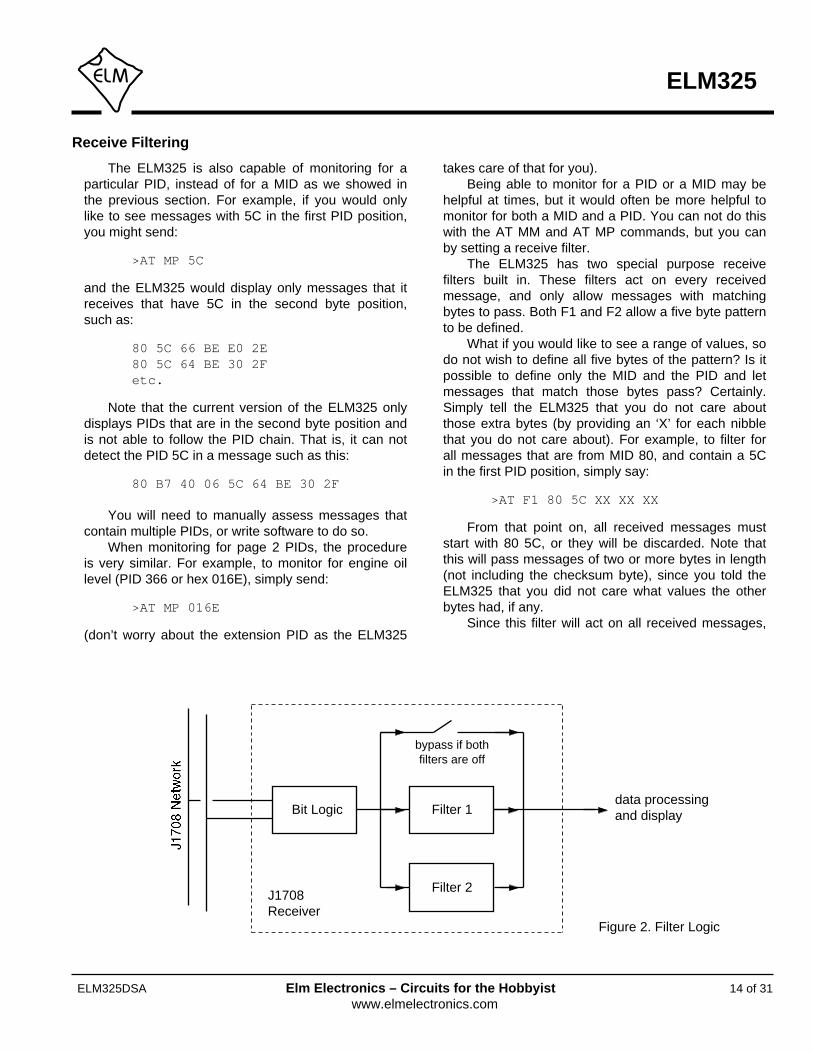
Figure 2. Filter Logic
Bit Logic Filter 1
bypass if bothfilters are off
Filter 2
data processing and display
J1708Receiver

Getting Trouble Codes
Trouble (diagnostic) codes are usually broadcastover the J1708 network so that all devices can know ofproblems. They will be transmitted when a problem isfirst discovered, while it is active, and when it clears.For this reason, all that you should normally have to dois monitor for the Trouble Code PID (it is C2 or decimal194). Since this is likely to be a very common use ofthe ELM325, we have built in a special function just forthis. To monitor for currently active trouble codes,simply send the command:
>AT TC
and the IC will configure the filters that you need forreceiving them. Note that if you have defined the filterspreviously for another function, the ELM325 will notchange your settings. It will instead treat this commandas if you had entered AT GM, so be careful.
If there are no trouble codes found in the time setby the AT ST timer, the AT TC command will returnwith a response of ‘NO DATA.’ If there are troublecodes found, they will be printed out for you.
The AT TC command doesn’t do anything that youcan not do, it just saves a few steps for you. If youwish to do exactly as the TC command does, try this:
>AT F1 XX C2 XX XX XX
>AT F2 XX C0 XX C2 XX
>AT GM
The filtering for C0 in the F2 setting is done so thatany long responses (multi section parameter IDs) will
also be detected and displayed.The AT GM command is actually quite a handy
one to use when you wish to look for specificmessages on the J1708 bus. Simply set the filters asrequired, ensure that the AT ST timer is set properly(some PIDs are only broadcast every 10 seconds),and then send AT GM. Of course, you could also setthe filters and then use the AT MA command, but thatcommand does not time out – you must manually stopit by pressing a key on the keyboard (or sending onefrom your program). The AT GM command will stopwaiting for a message after the AT ST time, which isoften more useful. A variation of this command, theGet One (AT GO) is also very useful as it acts exactlylike AT GM, except that it only gets one responsebefore returning immediately to the prompt.
We have discussed the monitoring for troublecodes that are being broadcast over the network, butwhat if you should wish to actually ask the modules fortrouble codes? You can do this easily as well – all youneed to do is send a request like this:
>C2
and the ELM325 will return with either a response fromthe MID(s), or it will will say ‘NO DATA’. The sendingof requests such as this is discussed further in the nextsection (Making Requests).
15 of 31
ELM325
ELM325DSA Elm Electronics – Circuits for the Hobbyistwww.elmelectronics.com
Receive Filtering (continued)
you may use it with any of the AT Commands that areavailable. For example, to see all messages that theJ1708 Receiver logic is now passing, simply send:
>AT MA
Of course, you may still use AT MM or MP when afilter has been defined, but then the received messagemust also meet the MM or MP condition.
As shown in Figure 2, the ELM325 also contains asecond filter that you may define in exactly the sameway. If a second filter is defined, then messages that
meet either the F1 or the F2 criteria are allowed topass on (and if neither filter has been defined, allmessages will be allowed to pass).
There are a few more examples of how to definethese filters in the next section (Getting TroubleCodes) and also in the Automatic Receive Filterssection. Creating filters is not very difficult if you knowwhat you expect the received message to ‘look’ like.

16 of 31
ELM325
ELM325DSA Elm Electronics – Circuits for the Hobbyistwww.elmelectronics.com
Making Requests
Using the ELM325 to send messages on theJ1708/J1587 bus is very similar to sending OBDmessages with our other products (the ELM327, etc.).Simply provide the data bytes that you want sent andthe ELM325 takes care of the details for you.
For example, assume that you wish to send thebytes 11 22 33 44 for some reason. Simply providethem to the ELM325 from the prompt:
>11 22 33 44
and the IC will add the MID and checksum for youbefore sending the entire message. You can provideas many as 21 data bytes (42 digits) to be sent in thismanner.
As a another example, assume that you wish tomake a request for PID BE data (this is the engine rpmPID that was discussed previously). PID 00 is used torequest a parameter, so to request parameter BE,simply send:
>00 BE
The ELM325 adds your MID for you, as well as thechecksum at the end, then transmits the entiremessage. Note that the MID and checksum are onlyadded if you have left the auto formatting on – if youhave turned it off, only the bytes that you provide willbe transmitted.
Similarly, if you wish to obtain % engine load (alsodiscussed previously), then send:
>00 5C
What if the information being requested iscurrently being broadcast regularly, and you only wishto see one message in response, not many? TheELM325 allows you to specify a single digit for thenumber of responses that you wish to see. Just add itafter the bytes. For example, to see only one responsefor the above request, send:
>00 5C 1
and the IC will return with a prompt after receiving onlyone message. The count that you provide is a hexdigit, and can have values from 0 to F.
Since these requests for parameters may be verycommon, we have simplified matters a little for you.The ELM325 always monitors what you are sending,and if it finds that you are sending a single byte only(while auto formatting is on), it will assume that you
are making a request for a parameter, and it will addthe 00 for you. That is, to request parameter BE,simply send:
>BE
and to obtain only 1 response for parameter 5C, send:
>5C 1
The page 2 parameters normally add a littlecomplexity to your sending, but with the ELM325’sautomatic formatting, they are again just a matter ofentering the PID number. To request the engine oillevel (PID 016E), simply send:
>016E
and if you wish to limit the number of responses to say3, send:
>016E 3
Note that the automatic formatting will only changeyour data bytes if you send a single byte or two bytesthat begin with 01. All other messages will remainunaffected, and will be transmitted exactly as provided.
This of course leads to the question ‘but what if Iwant to send a single byte message, or a two bytemessage that begins with 01?’. Then you will need toturn the automatic formatting off and send the entiremessage yourself (you will need to provide the MIDand the checksum too). Fortunately, it would be a veryspecial case if you wanted to send only a PID numberor if you wanted to send a single byte with PID 01(which has been discouraged since PIDs 194 to 196were introduced in 1988).
The above said to simply send a few bytes and allwould be well, if the auto formatting was on. But howdoes the IC know what messages to look for in theresponse? That is, what about setting the filters so thatthe ELM325 can selectively receive only the desiredresponse? That is taken care of for you too, even if theauto formatting is off. The next section discusses this.

Automatic Receive Filters
The ELM325 receiver always accepts bytes fromthe J1708 data stream, and then decides if they shouldbe passed on to the other logic, or discarded. Thisdecision to pass the messages on or not is done withselective logic called filters. You can set theseselective filters yourself (see the Receive Filteringsection), or allow the ELM325 to do it for you.
If you do not set either receive filter, and send amessage, the ELM325 will choose filter settings foryou based on the content of your message (theautomatic formatting does not have to be on for this tohappen). The settings may not be perfect for everysituation, but they will be acceptable for most. Thechart in Figure 3 shows what the settings will be fordifferent messages that you might send.
If you do not agree with the filter settings that theELM325 chooses for you, then simply define your own,using the AT F1 and AT F2 commands. Also if you
17 of 31
ELM325
ELM325DSA Elm Electronics – Circuits for the Hobbyistwww.elmelectronics.com
have already chosen filters, and would now prefer thatthe ELM325 choose them for you, then turn off thefilter(s) that you have enabled. To turn off filter 1, forexample, send the following:
>AT F1
Note that there are no parameters provided withthis command – just the AT and the F1. Similarly,disabling F2 is done with AT F2.
Seeing how the ELM325 sets its filters should atleast provide a starting point, if you are looking forspecific data. With a little experimentation, you will findthat it is not that difficult to set the filters, and so limitwhat is printed by the ELM325.
Figure 3. Filter Settings When Sending Messages to the ECU
PID Request
the send data looks like...
Filter 1
Filter 2
MID 00 PID XX PID XX XX XX
Description
MID FF 00 PIDExtended PID Request (page 2)
MID 80 PID RxMID RxMID PID XX XX XXComponent Specific (page 1)
MID FF 80 PID RxMID RxMID FF PID XX XXComponent Specific (page 2)
MID C3 03 RxMID PID RxMID C4 XX XX XXDiagnostic DataRequest
(data that does not match any of the above)
All other requests
XX C0 XX PID XX
XX FF PID XX XX
XX FF C0 XX PID
RxMID C0 XX C4 XX
(not used)
XX XX XX XX XX
RxMID C0 XX PID XX
RxMID FF C0 XX PID

Setting the MID
The Message ID (MID) is a single byte value thatis assigned by the SAE Truck and Bus Low SpeedCommunications Network Subcommittee. No twotransmitters on the network may use the same ID, sofor this reason, care should be used if you areexperimenting with different values of it.
The ELM325 uses the MID for the ‘Off-boardDiagnostics #1’ device by default. That is hex valueAC, or decimal value 172. If you wish to sendmessages using another MID, it is easily done with theSet MID command. For example, to use B4 (decimal180) which is for the Off-board Diagnostics #2 unit,then simply send the Set MID command:
>AT SM B4
Every message that the ELM325 sends from thatpoint (as long as auto formatting is on) will use theMID B4, instead of AC. Of course, you could also
18 of 31
ELM325
ELM325DSA Elm Electronics – Circuits for the Hobbyistwww.elmelectronics.com
There are occasions when a vehicle must respondwith more information than is able to fit in a single‘message’. In these cases, it responds with severaldata frames which the receiver must assemble intoone complete response. The following shows how thisis done with the SAE J1587 protocol.
Figure 3 of the Automatic Receive Filters sectionshowed that the ELM325 looks for two types ofresponses to a PID request. In the first, the requestedPID number appears in the very first data byteposition. This is the standard reply where a responseof 1 to 18 data bytes may be expected. The secondresponse that it looks for is one where the data beginswith the hex digits C0. The C0 PID is a special onethat is used to signify that the response is a specialmultisection one, and that the total number of databytes will be something greater than 18.
Figure 4 on the next page describes how the C0PID encodes the data contained. The very firstmessage (ie. section 0) has one extra byte to showhow many bytes in total are in the response. The nextlines received are identical to the first, except that theydo not have this one byte (and so have room for onemore data byte).
In total, there can be as many as 15 sections inone message, so the maximum number of data bytesthat can be sent in this way is 14 + 15 x 15 = 239 . If a
vehicle needs to send more than that, the J1587protocol has made provision for it with the TransportProtocol. While the ELM325 does not explicitly supportthe Transport Protocol in firmware, you can support itwith software (you will need one filter to watch for C5’sand the other to get C6’s).
The diagram in Figure 4 makes it fairly easy to seewhat each byte is doing, but again, you may wish torefer to the SAE standard for more complete details.We’ll just add a few notes for some of the more subtlepoints:
• The ELM325 does not assemble these messagesfor you – it must be done manually or withsoftware.
• There may be more than one MID responding to arequest for a PID.
• The segments are all sent in sequence, and youcan not request random resends.
pretend to be an engine or transmission, but youwould almost certainly cause problems, unless youwere in a teaching situation, with controlled conditions.
The MID assigned in this way stays in effect untilthe ELM325 restores its default values. This could bethrough the use of the AT D command, throughAT WS or AT Z, or from a power off and on. Thisversion of the ELM325 does not provideProgrammable Parameters (like the ELM327 or theELM329), so a preferred value (other than AC) can notbe stored in EEPROM.
Multiline Responses

19 of 31
ELM325
ELM325DSA Elm Electronics – Circuits for the Hobbyistwww.elmelectronics.com
Multiline Responses (continued)
C0 n PID Sections Bytes Data . . . Data ChecksumMID
sender’s ID# of bytes followingin this message (17)
multisection
PID
the PID thatwas requested
total # of Data bytesin all sections
14 data bytes
The first section:
All the other sections:
Figure 4. The Multisection Response
C0 n PID Sections Data . . . Data ChecksumMID
# of bytes followingin this message (3 to 17)
1 to 15 data bytes
this needs to be viewedas two nibbles:
thissection #
the lastsection #
ELM325
20 of 31ELM325DSA Elm Electronics – Circuits for the Hobbyistwww.elmelectronics.com
Setting the Timeout
Users often ask about how to obtain fasterscanning rates when obtaining information from avehicle. There is no definite answer for all vehicles, butyou can improve the response rate if you understandthe ELM325 internal timing process.
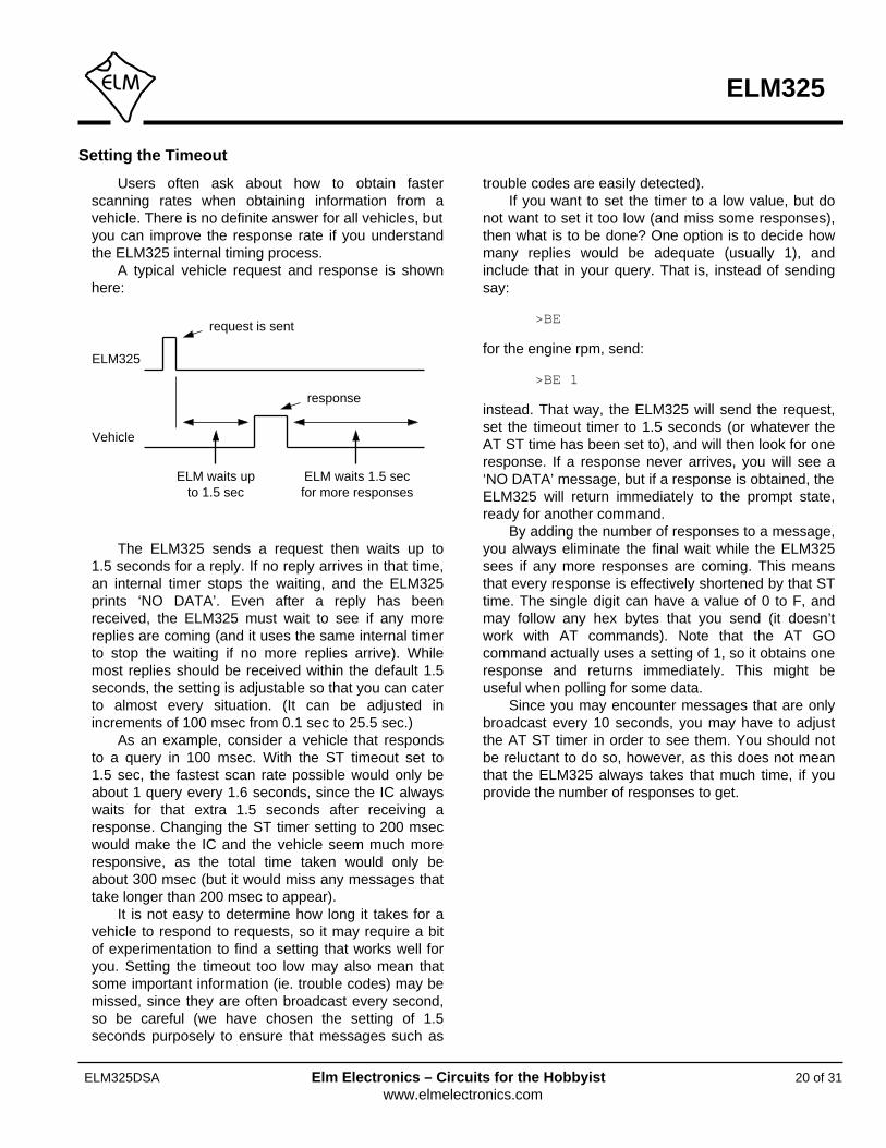
A typical vehicle request and response is shownhere:
The ELM325 sends a request then waits up to1.5 seconds for a reply. If no reply arrives in that time,an internal timer stops the waiting, and the ELM325prints ‘NO DATA’. Even after a reply has beenreceived, the ELM325 must wait to see if any morereplies are coming (and it uses the same internal timerto stop the waiting if no more replies arrive). Whilemost replies should be received within the default 1.5seconds, the setting is adjustable so that you can caterto almost every situation. (It can be adjusted inincrements of 100 msec from 0.1 sec to 25.5 sec.)
As an example, consider a vehicle that respondsto a query in 100 msec. With the ST timeout set to1.5 sec, the fastest scan rate possible would only beabout 1 query every 1.6 seconds, since the IC alwayswaits for that extra 1.5 seconds after receiving aresponse. Changing the ST timer setting to 200 msecwould make the IC and the vehicle seem much moreresponsive, as the total time taken would only beabout 300 msec (but it would miss any messages thattake longer than 200 msec to appear).
It is not easy to determine how long it takes for avehicle to respond to requests, so it may require a bitof experimentation to find a setting that works well foryou. Setting the timeout too low may also mean thatsome important information (ie. trouble codes) may bemissed, since they are often broadcast every second,so be careful (we have chosen the setting of 1.5seconds purposely to ensure that messages such as
trouble codes are easily detected).If you want to set the timer to a low value, but do
not want to set it too low (and miss some responses),then what is to be done? One option is to decide howmany replies would be adequate (usually 1), andinclude that in your query. That is, instead of sendingsay:
>BE
for the engine rpm, send:
>BE 1
instead. That way, the ELM325 will send the request,set the timeout timer to 1.5 seconds (or whatever theAT ST time has been set to), and will then look for oneresponse. If a response never arrives, you will see a‘NO DATA’ message, but if a response is obtained, theELM325 will return immediately to the prompt state,ready for another command.
By adding the number of responses to a message,you always eliminate the final wait while the ELM325sees if any more responses are coming. This meansthat every response is effectively shortened by that STtime. The single digit can have a value of 0 to F, andmay follow any hex bytes that you send (it doesn’twork with AT commands). Note that the AT GOcommand actually uses a setting of 1, so it obtains oneresponse and returns immediately. This might beuseful when polling for some data.
Since you may encounter messages that are onlybroadcast every 10 seconds, you may have to adjustthe AT ST timer in order to see them. You should notbe reluctant to do so, however, as this does not meanthat the ELM325 always takes that much time, if youprovide the number of responses to get.
ELM325
Vehicle
request is sent
response
ELM waits upto 1.5 sec
ELM waits 1.5 secfor more responses

ELM325
21 of 31ELM325DSA Elm Electronics – Circuits for the Hobbyistwww.elmelectronics.com
Restoring Order
There may be times when the ELM325 settingshave been adjusted, and it’s not responding properly.Perhaps you are not sure of the present settings (butyou do know that you were getting responses before,and are now not seeing any). Perhaps you have toldthe ELM325 to monitor all data, and there are screensand screens of data flying by.
The ELM325 can always be interrupted from atask by a single keystroke from the keyboard. As partof its normal operation, the ELM325 constantly checksfor any received characters on the serial port, and iffound, it will stop what it is doing at the nextopportunity. This may mean that it will continue tosend the information for the current line, then stop,print a prompt character, and wait for your input. Thestopping may not always seem immediate if it has justbegun printing a line, for example, so be patient.
There may be times when the problems seemmore serious and you don’t remember just what youdid to make them so bad. Perhaps you have ‘adjusted’the timer, and experimented with the filters, or perhapstried to see what happens if the MID byte is changed.To reset only the filters to their initial state, simplysend:
>AT F1
then
>AT F2
and the ELM325 will remove any settings that youhave made to either filter.
If the problem is a little more involved than this,
then all of the settings can be reset by sending the ‘setto Defaults’ command:
>AT D
This is usually enough to restore order, but ofcourse it removes all of the settings that you havemade (echo, linefeeds, etc), so should only be usedwhen you truly want all the settings to be restored totheir default values.
If the AT D command still does not bring theexpected results, it may be necessary to do somethingmore drastic – like resetting the entire IC. There are afew ways that this can be performed with the ELM325.One way is to simply remove the power and thenreapply it. Another way that acts exactly the same wayas a power off and then on is to send the full resetcommand:
>AT Z
It takes approximately one second for the IC toperform this reset, initialize everything and then testthe four status LEDs in sequence. A much quickeroption is available, however, if the led test is notrequired – the ‘Warm Start’ command:
>AT WS
The AT WS command performs a software reset,restoring the same items as AT Z, but it does notperform the LED test.
About J1922
SAE J1922 is another standard that may be usedby heavy duty trucks and busses. The data format issimilar enough to J1587 that you may use yourELM325 circuit with it.
J1922 uses a number of predefined messages forcommunicating status and performing various controlfunctions. These are either broadcast at a regular rate,or provided on demand, just like J1587. Unlike J1587,they do not use PIDs for defining functions though –they do that with the MID byte. The J1708 standarddefines MIDs 45 to 56 (ie. 69 to 86 decimal) for usewith J1922).
The messages may be from 2 to 23 bytes in lengthwith J1922 (21 data bytes are actually allowed by
J1708 if the vehicle’s engine is not running, and it’s notmoving). This is not an issue with the ELM325, as it iscapable of receiving an unlimited number of bytes, andis able to send as many as 21 data bytes (23 total) ifthe automatic formatting is on.
When monitoring for J1922 messages, use thesame commands as you would with J1587 – MA, MM,GM, etc. will all work. Note that AT MP will still worktoo, but it will filter for the first data byte (which is likelyof minimal use). The only concern might be that if youare sending messages and looking for responses, youmay have to define your own F1 and F2 filters (see theReceive Filtering section for more information on this).
22 of 31
ELM325
ELM325DSA Elm Electronics – Circuits for the Hobbyistwww.elmelectronics.com
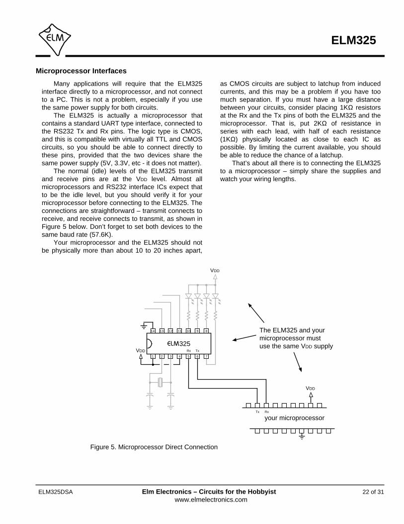
Many applications will require that the ELM325interface directly to a microprocessor, and not connectto a PC. This is not a problem, especially if you usethe same power supply for both circuits.
The ELM325 is actually a microprocessor thatcontains a standard UART type interface, connected tothe RS232 Tx and Rx pins. The logic type is CMOS,and this is compatible with virtually all TTL and CMOScircuits, so you should be able to connect directly tothese pins, provided that the two devices share thesame power supply (5V, 3.3V, etc - it does not matter).
The normal (idle) levels of the ELM325 transmitand receive pins are at the VDD level. Almost allmicroprocessors and RS232 interface ICs expect thatto be the idle level, but you should verify it for yourmicroprocessor before connecting to the ELM325. Theconnections are straightforward – transmit connects toreceive, and receive connects to transmit, as shown inFigure 5 below. Don’t forget to set both devices to thesame baud rate (57.6K).
Your microprocessor and the ELM325 should notbe physically more than about 10 to 20 inches apart,
as CMOS circuits are subject to latchup from inducedcurrents, and this may be a problem if you have toomuch separation. If you must have a large distancebetween your circuits, consider placing 1KΩ resistorsat the Rx and the Tx pins of both the ELM325 and themicroprocessor. That is, put 2KΩ of resistance inseries with each lead, with half of each resistance(1KΩ) physically located as close to each IC aspossible. By limiting the current available, you shouldbe able to reduce the chance of a latchup.
That’s about all there is to connecting the ELM325to a microprocessor – simply share the supplies andwatch your wiring lengths.
Microprocessor Interfaces
The ELM325 and yourmicroprocessor mustuse the same VDD supply
your microprocessorTx Rx
VDD
325
1 2 3 4 5 6 7
891011121314
TxRxVDD
VDD
Figure 5. Microprocessor Direct Connection
23 of 31
ELM325
ELM325DSA Elm Electronics – Circuits for the Hobbyistwww.elmelectronics.com
Example Applications
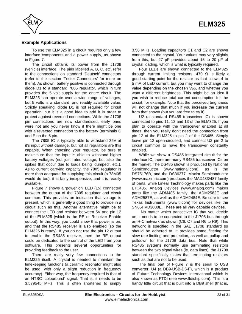
To use the ELM325 in a circuit requires only a fewinterface components and a power supply, as shownin Figure 7.
The circuit obtains its power from the J1708(vehicle) interface. The pins labelled A, B, C, etc. referto the connections on standard ‘Deutsch’ connectors(refer to the section ‘Tester Connectors’ for more onthem). As shown, battery positive is connected throughdiode D1 to a standard 7805 regulator, which in turnprovides the 5 volt supply for the entire circuit. TheELM325 can operate over a wide range of voltages,but 5 volts is a standard, and readily available value.Strictly speaking, diode D1 is not required for circuitoperation, but it is a good idea to add it in order toprotect against reversed connections. While the J1708pin connections are now standardised, early oneswere not and you never know if there might be onewith a reversed connection to the battery (terminals Cand E on the 6 pin.
The 7805 IC is typically able to withstand 35V atit’s input without damage, but not all regulators are thiscapable. When choosing your regulator, be sure tomake sure that the input is able to withstand higherbattery voltages (not just rated voltage, but also thespikes that occur due to loads being ‘dumped’, etc.).As to current carrying capacity, the 7805 regulator ismore than adequate for supplying this circuit (a 78M05would do too), it is fairly inexpensive, and it is readilyavailable.
Figure 7 shows a ‘power on’ LED (L5) connectedbetween the output of the 7805 regulator and circuitcommon. This provides an indication that voltage ispresent, which is generally a good thing to provide in acircuit such as this. Another alternative might be toconnect the LED and resistor between 5V and pin 12of the ELM325 (which is the RE or Receiver Enableoutput). In this way, you could show that power is on,and that the RS485 receiver is also enabled (so theELM325 is ready). If you do not use the pin 12 outputto enable the RS485 receiver, then the RE outputcould be dedicated to the control of the LED from yoursoftware. This presents several opportunities forproviding feedback to the user.
There are really very few connections to theELM325 itself. A crystal is needed to maintain thetimekeeping functions (a ceramic resonator might alsobe used, with only a slight reduction in frequencyaccuracy). Either way, the frequency required is that ofan NTSC ‘colourburst’ signal. That is, it needs to be3.579545 MHz. This is often shortened to simply
3.58 MHz. Loading capacitors C1 and C2 are shownconnected to the crystal. Your values may vary slightlyfrom this, but 27 pF provides about 15 to 20 pF ofcrystal loading, which is what is typically required.
Four LEDs are shown connected to the ELM325through current limiting resistors. 470 Ω is likely agood starting point for the resistor as that allows 4 to5 mA of LED current, but you may want to change thevalue depending on the chosen VDD, and whether youwant a different brightness. This might be an idea ifyou wish to reduce total current consumption for thecircuit, for example. Note that the perceived brightnesswill not change that much if you increase the currentfrom that shown (but you are free to try it).
U2 (a standard RS485 transceiver IC) is shownconnected to pins 11, 12 and 13 of the ELM325. If youplan to operate with the transceiver enabled at alltimes, then you really don’t need the connection frompin 12 of the ELM325 to pin 2 of the DS485. Simplyleave pin 12 open-circuited, and connect U2 pin 2 tocircuit common to have the transceiver constantlyenabled.
While we show a DS485 integrated circuit for theinterface IC, there are many RS485 transceiver ICs onthe market. The DS485 shown is produced by NationalSemiconductor (www.national.com), as is theDS75176B, and the DS36277. Maxim Semiconductor(www.maxim-ic.com) produces the MAX483/487 familyof parts, while Linear Technology makes parts like theLTC485. Analog Devices (www.analog.com) makesparts like the ADM485 family, the ADM2582E andADM2587E, as well as the ADM2484E. Be sure to seeTexas Instruments (www.ti.com) for devices like theSN65HVD3080E. These are all very capable devices.
No matter which transceiver IC that you decideon, it needs to be connected to the J1708 bus throughan R-C network as shown (C6, C7 and R6 to R9). Thisnetwork is specified in the SAE J1708 standard soshould be adhered to. It provides some filtering forslew rate limiting and protection, as well as pullup andpulldown for the J1708 data bus. Note that whileRS485 systems normally use terminating resistorsbetween the two signal wires (ie. data lines), the J1708standard specifically states that terminating resistorssuch as that are not to be used.
The final part of Figure 7 is the serial to USBconverter, U4 (a DB9-USB-D5-F), which is a productof Future Technology Devices International which isalso known as FTDI (see www.ftdichip.com). This is ahandy little circuit that is built into a DB9 shell (that is,

3 4
Example Applications (continued)
24 of 31
ELM325
ELM325DSA Elm Electronics – Circuits for the Hobbyistwww.elmelectronics.com
Figure 7.A J1708 to USB Interpreter
2 (RxD)
X13.579 MHz
C227pF
USBInterface(mini B)
J1708Interface
R1-4470Ω
+5V
C127pF
3 (TxD)
5 (SG)
1 (DCD)
4 (DTR)
6 (DSR)
7 (RTS)
8 (CTS)
+5V1 2
DS485
325
1 2 3 4 5 6 7
891011121314
U1
L1-L4
C62.2nF
U2
R5470Ω
+5V
C50.1µF
‘Power’L5
+
BatteryPositive
C (B)
Ground
+5V
C40.01µF
D11N4002
U3
7805C3
10µF50V
in out
com
FTDI
DB9-USB-D5-F
9 (RI)
+5V
R104.7KΩ
D21N4148
Note:The terminal labels are for a 6 pin Deutsch connector(the 9 pin connections are shown in brackets)
E (A)
A (F)
B (G)
J1708 +
J1708 -
R747Ω
R647Ω
C72.2nF R9
4.7KΩ
+5V
R84.7KΩ
U4
5678

Capacitors (16V or greater, except as noted)
C1, C2 = 27pFC3 = 10µF 50VC4 = 0.01uFC5 = 0.1µFC6, C7 = 2.2nF (2200pF)
MiscX1 = 3.579545 MHz crystal6 or 9 pin Deutsch connector8 pin DIP socket14 pin DIP socket
SemiconductorsD1 = 1N4001D2 = 1N4148L1, L2, L3, L4 = Yellow LEDL5 = Green LEDU1 = ELM325U2 = DS485 (RS485 transceiver)U3 = 7805 (5V, 1A regulator)U4 = FTDI DBP-USB-D5-F (USB I/F)
Resistors (1/8W or greater)
R1, R2, R3, R4, R5 = 470 ΩR6, R7 = 47 ΩR8, R9, R10 = 4.7 KΩ
25 of 31
ELM325
ELM325DSA Elm Electronics – Circuits for the Hobbyistwww.elmelectronics.com
Figure 8. Parts List for Figure 7
it looks like a 9 pin serial connector, with a mini USBsocket where the cable normally connects). It obtainsit’s power from the PC through the USB cable, so isnot a burden on the ELM325 circuit. In fact, the FTDImodule will even try to power the ELM325 whenconnected, which is why we added D2 and R10 – toblock any reverse current from flowing back into theELM325.
There isn’t much more that that we can say aboutthe FTDI module, except that it works as advertised,and works well. It requires software to be installedbefore you can use it, but that is available at their website (www.ftdichip.com) for Macintosh, Windows, andLinux. Go to Drivers, then choose VCP Drivers for theneeded virtual com port support. Once the software isinstalled, you may ‘talk’ to the ELM325 circuit withstandard serial interface software (such asHyperTerminal or ZTerm), or with custom interfacesoftware.
There are other RS232 to USB solutions availablesuch as the CP2102 from Silicon Laboratories(www.silabs.com), or you might try other devices such
as a Bluetooth or Wi-Fi module. We only show theFTDI product here as one possible option.
The final circuit that we offer is that of Figure 9. Itis identical to that in Figure 7, except that we show adiscrete RS232 interface connected to the ELM325’spins 5 and 6. This circuit is more than adequate for thisapplication, and is relatively low in cost. (It is also thesame as the one that we suggest with our ELM327and ELM329 integrated circuits.) Of course, if youwant to reduce the amount of wiring, you may wish toconsider products like the MAX232 family from MaximIntegrated Products (www.maxim-ic.com), and similardevices.
That should get you started with the ELM325. Itactually needs very few components to make a fullyfunctioning circuit, so should not be that difficult orexpensive to build. If you should need help, check thehelp pages on our web site, or write an email to ourtechnical support ([email protected])and we’ll do what we can to get you going.
Example Applications (continued)

3 4
ELM325
26 of 31ELM325DSA Elm Electronics – Circuits for the Hobbyistwww.elmelectronics.com
Example Applications (continued)
Figure 9. An RS232 Serial Interface
2 (RxD)
RS232Interface
(DB9F)
+5V
3 (TxD)
5 (SG)
1 (DCD)
4 (DTR)
6 (DSR)
7 (RTS)
8 (CTS)
4.7KΩ
10KΩ
10KΩ
1N4148
1N4148
0.1µF
+5V
4.7KΩ
10KΩ2N3906
2N3904
3.579 MHz
27pF
J1708Interface
4 x 470Ω
+5V
27pF
+5V1 2
DS485
325
1 2 3 4 5 6 7
891011121314
U1
2.2nF
470Ω
+5V
0.1µF
‘Power’
+
BatteryPositive
C (B)
Ground
+5V
0.01µF
1N4002
U3
7805
10µF50V
in out
com
Note:The terminal labels are for a 6 pin Deutsch connector(the 9 pin connections are shown in brackets)
E (A)
A (F)
B (G)
J1708 +
J1708 -
47Ω
47Ω
2.2nF 4.7KΩ
+5V
4.7KΩ
5678

27 of 31ELM325DSA Elm Electronics – Circuits for the Hobbyistwww.elmelectronics.com
ELM325
Tester Connectors
The tester that you make will need to connect tothe vehicle’s diagnostics port using a cable and specialconnector. You may need a few connectors for this, asthe types used by the manufacturers have varied overthe years. The two most common ones that you willfind are the 6 pin, and the 9 pin ‘Deutsch’ connectors.Deutsch Industrial is a multinational company thatmakes products for use in harsh environmentalconditions.
The following shows the pin configurations for the‘Deutsch’ connectors, and lists part numbers for each.Should you wish to make your own connectors, you
6 pin ‘Deutsch’ test connector(looking into the open end)
A
B
C
D
E
F
9 pin ‘Deutsch’ test connector(looking into the open end)
Shell
# 12Socket Pins
Deutsch Industrial Amphenol Sine Systems
HD16-6-12Sor
HD16-6-96S
AHD16-6-12S(889-1064-ND)
orHD16-6-12S-B010
(889-1063-ND)
AT62-210-1231(889-1053-ND)
or65-54748
(889-1057-ND)
1062-12-0122
will need to buy a shell (or casing) as well as the metalpins to insert into it.
While the Deutsch Industrial products are what isnormally specified for these connectors, you may findthe Amphenol parts to be an acceptable alternativeand possibly easier to obtain in your area. We providea Digi-Key (www.digikey.com) part number in bracketsunder each Amphenol part to help you if ordering fromthem.
Shell
# 16Socket Pins
Deutsch Industrial Amphenol Sine Systems
HD16-9-1939S AHD16-9-1939S(889-1059-ND)
AT62-16-0622(AT62-16-0622-ND)
orAT62-16-0122
(889-1049-1-ND)or
65-54757(889-1055-ND)
1062-12-0122AB
CD E
F
G
H
J
Error Messages and Alerts
BUFFER FULL
The ELM325 provides an internal memory space(or ‘buffer’) for temporarily storing data bytes beforethey are transmitted as RS232 data. The state of thisbuffer is continually monitored and a warning is given ifit should become full (as data will be lost if thatcontinues).
If you are receiving BUFFER FULL messages,then you may be trying to connect to a system that isoperating at a non-standard baud rate, or possibly hasexcessive noise. You may reduce the amount of datatransmitted (and so reduce the amount of data thatneeds to be put into the buffer) by setting the filters toonly show specific data. You might also try settingchecksums off (AT C0), spaces off (AT S0) andpossibly error messages off (AT EM0) to reduce theamount of data being sent.
BUS BUSY
Messages provided to the ELM325 are sent after acertain time passes (based on the message priority),and while no other device is sending. If another deviceshould begin sending at the same time as theELM325, then both devices will stop, wait some time,and attempt a resend. Usually, this is sufficient to allowa message to be successfully sent, but should theELM325 not be successful after a few seconds, it willstop trying and report that the bus is too busy. If thisoccurs, you will need to determine if there is a problem(eg. possibly in the wiring), and decide if you wish totry again.
<DATA ERROR
This message appears if the checksum calculationdid not agree with the one that was sent from thevehicle. It means that there is a problem with one ormore of the bytes received. There could have been anoise burst which interfered, or possibly there is acircuit problem. Try the command again – if it was anoise burst, it may be received correctly the secondtime.
NO DATA
The IC waited for the period of time (as set by the
AT ST timer), and detected no response from thevehicle. It may be that the vehicle did not respond, orpossibly that it did, but the filters were set so that theresponse was not seen. If you are certain that thereshould have been a response, try increasing the STtime (to be sure that you have allowed enough time forthe ECU to respond).
<PROT ERROR
A protocol error occurs if there was a violation ofthe timing requirements before the message. Thismight be due to some noise or another problem, butthe message is intended to only make you aware thatsomething isn’t quite right. If the checksums agree (noDATA ERROR), then the content of the messageshould be OK. If the problem persists, there may bean issue with the sender of the message which wouldrequire further investigation.
<RX ERROR
A receive error occurs if there was a problemdetected with the low level J1708 data. That is, therewas a problem with the actual length of the bytereceived and its component bits. This usually occurs ifthe baud rate is incorrect (which should not be thecase if you are connected to a J1708 system, as theyall use 9600 bps).
STOP?
If an operation is interrupted by a received RS232character, the ELM325 will print STOP? then return tothe prompt state. If you should see this response, thensomething that you have done has interrupted theELM325.
?
This is the standard response for a misunderstoodcommand received on the RS232 input. Usually it isdue to a typing mistake, but it can also occur if you tryto do something that is not appropriate for thecommand (for example, the AT GM command will givean error if a filter has not been set).
The following describes the messages that thisversion of the ELM325 sends to tell you of a problem.
28 of 31ELM325DSA Elm Electronics – Circuits for the Hobbyistwww.elmelectronics.com
ELM325

29 of 31
ELM325
ELM325DSA Elm Electronics – Circuits for the Hobbyistwww.elmelectronics.com
Outline Diagrams
The diagrams at the right show the two packagestyles that the ELM325 is available in.
The first shows our ELM325P product in what iscommonly known as a 300 mil Plastic DIP (or PDIP)package. It is used for through hole applications.
The ELM325SM package shown at right is oursurface mount option. It is 3.90 mm wide (or 150 mils)and is known as a narrow Small Outline IC (or SOIC)package. We have chosen to simply refer to it as anSM (surface mount) package.
The drawings shown here provide the basicdimensions for these ICs only. Please refer to thefollowing Microchip Technology Inc. documentation formore detailed information:
• The Microchip Packaging Specification, documentname en012702.pdf (7.5MB). At the home page(www.microchip.com), select Design Support thenDocumentation then Packaging Specifications, or goto www.microchip.com/packaging
• The PIC12(L)F1822/PIC16(L)F1823 Data Sheet, filename 41413C.pdf (7 MB). At the www.microchip.comhome page, use the Search Data Sheets box to lookfor 16F1823.
Note: all dimensions shown are in mm.
ELM325P
ELM325SM
3.90
6.00
1.27
These integrated circuits are 14 pin devices, available in either a 300 mil wide plastic DIP format, or in a 150 mil (3.90 mm body) SOIC surface mount type of package. We do not currently offer any other package options for this device.
The ELM325 part numbers are as follows:
300 mil 14 pin Plastic DIP..............................ELM325P 150 mil 14 pin SOIC....................................ELM325SM
Ordering Information
2.54
max10.92
6.35

E
Electrical Characteristics, 4
Error Messages and Alerts, 28
Example Applications
Basic, 23
Figure 7 (USB), 24
Figure 7 Parts List, 25
Figure 9 (RS232), 26
F
Features, 1
Figure 7, 24
Filtering, Receive, 14-15
Filters, Automatic Receive, 17
G
Getting Trouble Codes, 15
I
Interfaces, Microprocessor, 22
J
J1587 Commands, 12
Number of responses, 16, 20
J1922, About, 21
L
Listening to a Vehicle, 13
M
Making Requests, 16
Maximum Ratings, Absolute, 4
Index
A
About J1922, 21
Absolute Maximum Ratings, 4
Amphenol Connectors, 27
Applications, Example, 23-26
AT Commands
Descriptions, 8-10
Introduction, 7
Sending, 11
Summary, 7
AT ST command, 10, 20
Automatic Receive Filters, 17
B
Block Diagram, 1
BUFFER FULL, 28
BUS BUSY, 28
C
Codes, Getting Trouble, 15
Commands, AT
Descriptions, 8-10
Summary, 7
Commands, J1587, 12
Communicating with the ELM325, 5-6
Connectors, Tester, 27
Contents, 2
Connection Diagram, 1
Copyright and Disclaimer, 2
D
DATA ERROR, 28
Description and Features, 1
Diagrams, Outline, 29
Disclaimer and Copyright, 2
Deutsch Connector, 27
30 of 31
ELM325
ELM325DSA Elm Electronics – Circuits for the Hobbyistwww.elmelectronics.com
Index (continued)
M (continued)
Message Filtering, 14, 17
Messages, Error, 28
Microprocessor Interfaces, 22
MID, Setting the, 18
Monitoring the Bus, 13
Multiline Responses, 18-19
N
NO DATA, 28
Number of Responses, 16, 20
O
Order, Restoring, 21
Ordering Information, 29
Outline Diagrams, 29
Overview, How to use the ELM325, 5
P
PDIP, 29
Pin Descriptions, 3
PROT ERROR, 28
R
Reading Trouble Codes, 15
Receive Filtering, 14-15
Receive Filters, Automatic, 17
Responses, Multiline, 18-19
Restoring Order, 21
Requests, Making, 16
RX ERROR, 28
S
Sending AT Commands, 11
Setting
Filters, 14-15
the MID, 18
Timeouts, 20
Specify the Number of Responses, 16, 20
STOP?, 28
Summary, AT Commands, 7
T
Tester Connectors, 27
Timeouts, Setting, 20
Trouble Codes, Getting, 15
U
Using the ELM325, 5
31 of 31
ELM325
ELM325DSA Elm Electronics – Circuits for the Hobbyistwww.elmelectronics.com