ELITE Series Garage Door Opener Installation . . . . . . . . . . . . . . .6-13 · 2017-05-25 ·...
41
CONTENTS Preparation . . . . . . . . . . . . . . . . 2-3 Assembly . . . . . . . . . . . . . . . . . 4-5 Installation . . . . . . . . . . . . . . . 6-13 Install the Door Control . . . . . . 14-15 Install the Protector System ® . . 16-19 Power. . . . . . . . . . . . . . . . . . 20-21 Adjustments . . . . . . . . . . . . . 22-24 Battery Backup* . . . . . . . . . . . 25-26 Operation . . . . . . . . . . . . . . . . . 27 Features . . . . . . . . . . . . . . . . . . 28 Door Control . . . . . . . . . . . . . 29-30 Remote Control . . . . . . . . . . . 31-32 To Erase the Memory . . . . . . . . . 32 To Open the Door Manually . . . . . 33 Maintenance . . . . . . . . . . . . . . . 34 Troubleshooting. . . . . . . . . . . 35-36 Accessories. . . . . . . . . . . . . . . . 37 Warranty. . . . . . . . . . . . . . . . . . 38 Repair Parts . . . . . . . . . . . . . 39-41 * If applicable ELITE Series Garage Door Opener LiftMaster 845 Larch Avenue Elmhurst, Illinois 60126-1196 ■ Please read this manual and the enclosed safety materials carefully! ■ Fasten the manual near the garage door after installation. ■ The door WILL NOT CLOSE unless the Protector System ® is connected and properly aligned. ■ Periodic checks of the garage door opener are required to ensure safe operation. ■ The model number label is located on the left side panel of your garage door opener. ■ This garage door opener is ONLY compatible with MyQ ® and Security✚ 2.0™ accessories. ■ DO NOT enable the Timer-to-Close feature if you are installing the garage door opener on a one-piece door. The Timer-to-Close is to be used ONLY with sectional doors. NOTE: If you are installing the garage door opener on a one-piece door, visit www.LiftMaster.com for installation instructions. www.LiftMaster.com Serial Number: Date of Purchase: Models • 8550 - DC Belt Drive with Battery Backup • 8557 - 3/4 hp Belt Drive FOR RESIDENTIAL USE ONLY Write down the following information for future reference: .
Transcript of ELITE Series Garage Door Opener Installation . . . . . . . . . . . . . . .6-13 · 2017-05-25 ·...

CONTENTS
Preparation . . . . . . . . . . . . . . . .2-3Assembly . . . . . . . . . . . . . . . . .4-5Installation . . . . . . . . . . . . . . . 6-13Install the Door Control . . . . . . 14-15Install the Protector System® . . 16-19Power. . . . . . . . . . . . . . . . . . 20-21Adjustments . . . . . . . . . . . . . 22-24Battery Backup*. . . . . . . . . . . 25-26Operation . . . . . . . . . . . . . . . . . 27Features . . . . . . . . . . . . . . . . . . 28Door Control . . . . . . . . . . . . . 29-30Remote Control . . . . . . . . . . . 31-32To Erase the Memory . . . . . . . . . 32To Open the Door Manually . . . . . 33Maintenance . . . . . . . . . . . . . . . 34Troubleshooting. . . . . . . . . . . 35-36Accessories. . . . . . . . . . . . . . . . 37Warranty. . . . . . . . . . . . . . . . . . 38Repair Parts . . . . . . . . . . . . . 39-41
* If applicable
ELITE Series Garage Door Opener
LiftMaster845 Larch Avenue
Elmhurst, Illinois 60126-1196
■ Please read this manual and the enclosed safety materials carefully!
■ Fasten the manual near the garage door after installation.
■ The door WILL NOT CLOSE unless the Protector System® is connected and properly aligned.
■ Periodic checks of the garage door opener are required to ensure safe operation.
■ The model number label is located on the left side panel of your garage door opener.
■ This garage door opener is ONLY compatible with MyQ® and Security✚ 2.0™ accessories.
■ DO NOT enable the Timer-to-Close feature if you are installing the garage door opener on a one-piece door. The Timer-to-Close is to be used ONLY with sectional doors.
NOTE: If you are installing the garage door opener on a one-piece door, visit www.LiftMaster.com for installation instructions.
www.LiftMaster.comSerial Number:
Date of Purchase:
Models • 8550 - DC Belt Drive
with Battery Backup • 8557 - 3/4 hp
Belt Drive
FOR RESIDENTIAL USE ONLY
Write down the following information for future reference:
.

2
Safety Symbol and Signal WordReviewThis garage door opener has been designed andtested to offer safe service provided it is installed,operated,maintained and tested in strictaccordance with the instructions and warningscontained in thismanual.When you see these Safety Symbols and SignalWords on the following pages, they will alert you tothe possibility of serious injury or death if you donot comply with the warnings that accompany them.The hazard may come from something mechanicalor from electric shock. Read the warnings carefully.
Mechanical
ElectricalWhen you see this Signal Word on the followingpages, it will alert you to the possibility of damage toyour garage door and/or the garage door opener ifyou do not comply with the cautionary statementsthat accompany it. Read them carefully.
Check the Door
To prevent possible SERIOUS INJURY orDEATH:
l ALWAYS call a trained door systemstechnician if garage door binds, sticks,or is out of balance. An unbalancedgarage door mayNOT reverse whenrequired.
l NEVER try to loosen,move or adjustgarage door, door springs, cables,pulleys, brackets or their hardware,ALL of which are under EXTREMEtension.
l Disable ALL locks and removeALL ropes connected to garage doorBEFORE installation and operatinggarage door opener to avoidentanglement.
To prevent damage to garage door andopener:
l ALWAYS disable locks BEFOREinstalling and operating the opener.
l ONLY operate garage door opener at120V, 60 Hz to avoid malfunction anddamage.
1. Disable locks and remove any ropesconnected to the garage door.
2. Lift the door halfway up. Release thedoor. If balanced, it should stay in place,supported entirely by its springs.
3. Raise and lower the door to check forbinding or sticking. If your door binds,sticks, or is out of balance, call a traineddoor systems technician.
4. Check the seal on the bottom of the door.Any gap between the floor and thebottom of the door must not exceed1/4 inch (6 mm).Otherwise, the safetyreversal systemmay not work properly.
5. The opener should be installed abovethe center of the door. If there is a torsionspring or center bearing plate in the wayof the header bracket, it may be installedwithin 4 feet (1.2 m) to the left or right ofthe door center. See page 7.
Torsion
SpringExtension
SpringOR
Tools Needed
21
3/16
7/16
1/2
5/32
5/16
5/8
9/16
1/4
7/16
Preparation

3
Carton InventoryAccessories will vary depending on the garage door opener model purchased. Depending on yourspecific model, other accessoriesmay be included with your garage door opener. The instructions forthese accessories will be attached to the accessory and are not included in thismanual. The imagesthroughout thismanual are for reference and your productmay look different.
A. Header bracketB. Pulley and bracketC. Door bracketD. Curved door armE. Straight door armF. TrolleyG. Emergency release rope and handleH. RailI. Garage door openerJ. Sprocket cover with hex screwsK. BeltL. Door controlM. White and red/white wireN. The Protector System®
Safety reversing sensors with white and white/black wire attached: Sending Sensor (1)Receiving Sensor (1) and Safety Sensor Brackets (2)
O. Safety labels and literatureP. Rail grease
Security+ 2.0™ Accessories880LMSmart Control Panel®
895MAXRemote Control
InstallationHardwareHex bolt 5/16"-18 x 7/8" (4) Lock washer 5/16" (4)Lag screw 5/16"-9 x 1-5/8" (2) Self-threading screw 1/4"-14 x 5/8" (2)Clevis pin 5/16" x 2-3/4" (1) Ring fastener (3)Clevis pin 5/16" x 1-1/4" (1) Carriage bolt 1/4"-20 x 1/2" (2)Clevis pin 5/16" x 1" (1) Wing nut 1/4"-20 (2)Nut 5/16"-18 (4)
DoorControl HardwareScrew 6AB x 1" (2)Screw 6-32 x 1" (2)Drywall anchors (2)Insulated staples
A B
C
J
N
I
OP
DE
F
H
GK
L
M
Not Provided
Not
Provided
Preparation

4
Assembly
1 Attach the Rail to the Garage Door Opener
To avoid possible SERIOUS INJURY to finger frommoving garage door opener:l ALWAYS keep hand clear of sprocket while operating opener.l Securely attach sprocket cover BEFORE operating.
To avoid SERIOUS damage to garage door opener, use ONLY those bolts/fastenersmounted inthe top of the opener.
NOTE: ONLY use the bolts removed from the garage door opener. Place the garage door opener onthe packing material to prevent scratching.
1. Model 8550: Remove the two bolts from the top of the garage door opener.Model 8557: Remove bolt and lock nut from the top of the garage door opener.
2. Align the rail and the styrofoam over the sprocket. Cut the tape from the rail, belt, andstyrofoam.
3. Model 8550: Fasten the rail with the previously removed bolts.Model 8557: Fasten the rail with the previously removed washered bolt and lock nut.
4. Position the belt around the garage door opener sprocket.5. Attach the sprocket cover over the garage door opener sprocket and attach with hex screws.
Model 8550
Model 8557
Washered Bolt
5/16"-18x1/2"Hex Screw
#8x3/8"
Lock Nut
Washered Bolt 5/16"-18x1/2"
(Mounted in the garage
door opener)
Model 8550 (2)
Model 8557 (1)
Hex Screw#8x3/8"(Packed with the sprocket cover)
Lock Nut
(Mounted in the
garage door opener)
Model 8557 (1)
Washered Bolt
5/16"-18x1/2"
Hex Screw
#8x3/8"
HARDWARE

5
Assembly
2 Tighten the Belt1. By hand, thread the spring trolley nut on the threaded shaft until it is finger tight against the
trolley. Do not use any tools.2. Insert a flathead screwdriver tip into one of the nut ring slots and brace it firmly against the
trolley.3. Tighten the spring trolley nut with an adjustable wrench or a 7/16" open end wrench about a
quarter turn until the spring releases and snaps the nut ring against the trolley. This sets thespring to optimum belt tension.
Spring Trolley Nut
(To motor unit)
Nut ring
slot
Nut Ring Nut Ring
AFTER RELEASE1-1/4"
(3.18 cm)
BEFORE1"
(2.5 cm)
1
2
3

6
Installation
IMPORTANT INSTALLATION INSTRUCTIONSWARNING
To reduce the risk of SEVERE INJURY or DEATH:1. READANDFOLLOWALL INSTALLATIONWARNINGS AND INSTRUCTIONS.2. Install garage door opener ONLY on properly balanced and lubricated garage door. An
improperly balanced door mayNOT reverse when required and could result in SEVEREINJURY or DEATH.
3. ALL repairs to cables, spring assemblies and other hardware MUST be made by a traineddoor systems technician BEFORE installing opener.
4. Disable ALL locks and remove ALL ropes connected to garage door BEFORE installingopener to avoid entanglement.
5. Install garage door opener 7 feet (2.13 m) or more above floor.6. Mount the emergency release within reach, but at least 6 feet (1.83 m) above the floor and
avoiding contact with vehicles to avoid accidental release.7. NEVER connect garage door opener to power source until instructed to do so.8. NEVER wear watches, rings or loose clothing while installing or servicing opener. They could
be caught in garage door or opener mechanisms.
9. Install wall-mounted garage door control:l within sight of the garage door.l out of reach of children atminimum height of 5 feet (1.5 m).l away fromALL moving parts of the door.
10. Place entrapment warning label on wall next to garage door control.11. Place manual release/safety reverse test label in plain view on inside of garage door.12. Upon completion of installation, test safety reversal system. Door MUST reverse on contact
with a 1-1/2" (3.8 cm) high object (or a 2x4 laid flat) on the floor.13. To avoid SERIOUS PERSONAL INJURY or DEATH from electrocution, disconnect ALL
electric and battery power BEFORE performing ANY service or maintenance.14. DO NOT enable the Timer-to-Close functionality if operating either one-piece or swinging
garage doors. To be enabled ONLY when operating a sectional door.
NOTE: If you are installing the garage door opener on a one-piece door, visit www.LiftMaster.com for installation instructions.

7
Installation
1 Determine the Header Bracket Location
To prevent possible SERIOUS INJURY or DEATH:l Header bracketMUST be RIGIDLY fastened to structural support on header wall or ceiling,
otherwise garage door might NOT reverse when required. DO NOT install header bracketover drywall.
l Concrete anchorsMUST be used if mounting header bracket or 2x4 into masonry.l NEVER try to loosen,move or adjust garage door, springs, cables, pulleys, brackets, or their
hardware, ALL of which are under EXTREME tension.l ALWAYS call a trained door systems technician if garage door binds, sticks, or is out of
balance. An unbalanced garage door might NOT reverse when required.l DO NOT enable the Timer-to-Close functionality if operating either one-piece or swinging
garage doors. To be enabled ONLY when operating a sectional door.
NOTE: If you are installing the garage door opener on a one-piece door, visit www.LiftMaster.com forinstallation instructions.Close the door and mark the inside vertical centerline of the garage door.Extend the line onto the header wall above the door. You can fasten the header bracket within 4 feet(1.22 m) of the left or right of the door center only if a torsion spring or center bearing plate is in the way;or you can attach it to the ceiling when clearance isminimal. (It may be mounted on the wall upside downif necessary, to gain approximately 1/2" (1 cm). If you need to install the header bracket on a 2x4 (on wallor ceiling), use lag screws (not provided) to securely fasten the 2x4 to structural supports.Open your door to the highest point of travel as shown. Draw an intersecting horizontal line on theheader wall 2" (5 cm) above the high point. This height will provide travel clearance for the top edge ofthe door.NOTE: If the total number of inches exceeds the height available in your garage, use the maximumheight possible, or refer to page 8 for ceiling installation.
Header Wall
Unfinished Ceiling
Vertical Centerline
of Garage Door
2x4
2x4
Structural
Supports
Level
(Optional)
OPTIONAL
CEILING
MOUNT FOR
HEADER
BRACKET
Sectional door with curved track
Header Wall
Track
2" (5 cm)
Highest Point of Travel
Door

8
Installation
2 Install the Header BracketYou can attach the header bracket either to the wall above the garage door, or to the ceiling. Follow theinstructions which will work best for your particular requirements.Donot install the header bracket overdrywall. If installing intomasonry, use concrete anchors (not provided).
HARDWARE
Lag Screw 5/16"-9x1-5/8"
OPTION AWALL INSTALLATION1. Center the bracket on the vertical centerline with the bottom edge of the bracket on the
horizontal line as shown (with the arrow pointing toward the ceiling).2. Mark the vertical set of bracket holes (do not use the holes designated for ceiling mount). Drill
3/16" pilot holes and fasten the bracket securely to a structural support with lag screws.
Wall Mount
Optional Mounting Holes
Vertical Centerline of Garage Door
(Header Wall)
Header Bracket
2x4 Structural Support
Door Spring
(Garage Door)Highest Point of Garage Door
Travel
Horizontal Line
Lag Screw
5/16" - 9 x 1-5/8"
OPTION B CEILING INSTALLATION1. Extend the vertical centerline onto the ceiling as shown.2. Center the bracket on the vertical mark, no more than 6" (15 cm) from the wall. Make sure the
arrow is pointing toward the wall. The bracket can be mounted flush against the ceiling whenclearance isminimal.
3. Mark the side holes. Drill 3/16" pilot holes and fasten bracket securely to a structural supportwith lag screws.
(Header Wall)
Ceiling Mounting Holes
(Finished Ceiling)
Vertical Centerline of Garage Door
Header Bracket
6" (15 cm) Maximum
Door Spring
(Garage Door)
Lag Screw
5/16" - 9 x 1-5/8"

9
Installation
3 Attach the Rail to the Header Bracket1. Align the rail with the header bracket. Insert the clevis pin through the holes in the header
bracket and rail. Secure with the ring fastener.NOTE: Use the packing material as a protective base for the garage door opener.
Ring
Fastener
Clevis Pin
5/16" X 2-3/4"
HARDWARE
Clevis Pin 5/16" x 2-3/4" Ring Fastener
4 Position the Garage Door Opener
To prevent damage to garage door, rest garage door opener rail on 2x4 placed on top section ofdoor.
1. Remove the packing material and lift the garage door opener onto a ladder.2. Fully open the door and place a 2x4 (laid flat) under the rail.
A 2x4 is ideal for setting the distance between the rail and the door. If the ladder is not tall enough youwill need help at this point. If the door hits the trolley when it is raised, pull the trolley release arm down todisconnect the inner and outer trolley. Slide the outer trolley toward the garage door opener. The trolleycan remain disconnected until instructed.
Connected Disconnected

10
Installation
5 Hang the Garage Door Opener
To avoid possible SERIOUS INJURY from a falling garage door opener, fasten it SECURELY tostructural supports of the garage. Concrete anchorsMUST be used if installing ANY brackets intomasonry.
Hanging your garage door opener will vary depending on your garage. Two representative installationsare shown. Yoursmay be different. Hanging brackets should be angled (Figure 1) to provide rigidsupport. On finished ceilings (Figure 2), attach a sturdymetal bracket to structural supports beforeinstalling the opener. This bracket and fastening hardware are not provided.
1. Measure the distance from each side of the motor unit to the structural support.2. Cut both pieces of the hanging bracket to required lengths.3. Drill 3/16" pilot holes in the structural supports.4. Attach one end of each bracket to a support with 5/16"-18x1-7/8" lag screws (not provided).5. Fasten the opener to the hanging brackets with 5/16"-18x7/8" hex bolts, lock washers and
nuts.6. Check to make sure the rail is centered over the door (or in line with the header bracket if the
bracket is not centered above the door).7. Remove the 2x4. Operate the door manually. If the door hits the rail, raise the header bracket.
NOTE: DO NOT connect power to opener at this time.
FIGURE 1 FIGURE 2
(Not Provided)
Lag Screws
5/16"- 18x1-7/8"
Measure
Distance
Hex Bolt 5/16"- 18x7/8", Lock Washer 5/16", Nut 5/16"-18
FIGURE 3
Not Provided
Finished CeilingUnfinished Ceiling
Hex Bolt 5/16"- 18x7/8" Nut 5/16"-18 Lock Washer 5/16"
HARDWARE

11
Installation
6 Install the Light Bulbs
To prevent possible OVERHEATING of the end panel or light socket:l Use ONLY A19 incandescent (100W maximum) or compact fluorescent (26W maximum)
light bulbs.l DO NOT use incandescent bulbs larger than 100W.l DO NOT use compact fluorescent light bulbs larger than 26W (100W equivalent).l DO NOT use halogen bulbs.l DO NOT use short neck or specialty light bulbs.
1. Pull on the top center of the light lens and rotate the light lens down.2. Insert an A19 incandescent (100Wmaximum) or compact fluorescent (26W, 100W equivalent)
light bulb into the light socket.NOTE: DO NOT use halogen, short neck, or specialty light bulbs as these may overheat the end panelor light socket. DO NOT use LED bulbs as theymay reduce the range or performance of your remotecontrol(s).
3. Rotate the lens up to close.
or or
7 Attach the Emergency Release Rope and Handle
To prevent possible SERIOUS INJURY or DEATH from a falling garage door:l If possible, use emergency release handle to disengage trolleyONLY when garage door is
CLOSED.Weak or broken springs or unbalanced door could result in an open door fallingrapidly and/or unexpectedly.
l NEVER use emergency release handle unless garage doorway is clear of persons andobstructions.
l NEVER use handle to pull door open or closed. If rope knot becomes untied, you could fall.
1. Insert one end of the emergency release rope through the handle.Make sure that “NOTICE” isright side up. Tie a knot at least 1 inch (2.5 cm) from the end of the emergency release rope.
2. Insert the other end of the emergency release rope through the hole in the trolley release arm.Mount the emergency release within reach, but at least 6 feet (1.83 m) above the floor,avoiding contact with vehicles to prevent accidental release and secure with a knot.
NOTE: If it is necessary to cut the emergency release rope, seal the cut end with a match or lighter toprevent unraveling. Ensure the emergency release rope and handle are above the top of all vehicles toavoid entanglement.
Trolley
Release Arm

12
Installation
8 Install the Door Bracket
Fiberglass, aluminum or lightweight steel garage doorsWILLREQUIRE reinforcement BEFOREinstallation of door bracket. Contact the garage door manufacturer or installing dealer for openerreinforcement instructions or reinforcement kit. Failure to reinforce the top section as requiredaccording to the door manufacturer may void the door warranty.
A horizontal and vertical reinforcement is needed forlightweight garage doors (fiberglass, aluminum, steel,doors with glass panel, etc.) (not provided). A horizontalreinforcement brace should be long enough to be securedto two or three vertical supports. A vertical reinforcementbrace should cover the height of the top panel. Contact thegarage door manufacturer or installing dealer for openerreinforcement instructions or reinforcement kit.
NOTE: Many door reinforcement kits provide for direct attachment of the clevis pin and door arm. In thiscase you will not need the door bracket; proceed to the next step.
SECTIONAL DOORS1. Center the door bracket on the previouslymarked vertical centerline used for the header
bracket installation. Note correct UP placement, as stamped inside the bracket.2. Position the top edge of the bracket 2"-4" (5-10 cm) below the top edge of the door, OR
directly below any structural support across the top of the door.3. Mark, drill holes and install as follows, depending on your door’s construction:
Metal or light weight doors using a vertical angle iron brace between the door panel support and thedoor bracket:
l Drill 3/16" fastening holes. Secure the door bracket using the two self threading screws.(Figure 1)
l Alternately, use two 5/16" bolts, lock washers and nuts (not provided). (Figure 2)Metal, insulated or light weight factory reinforced doors:
l Drill 3/16" fastening holes. Secure the door bracket using the self-threading screws. (Figure 3)
WoodDoors:l Use top and bottom or side to side door bracket holes. Drill 5/16” holes through the door and
secure bracket with 5/16"-18x2" carriage bolts, lock washers and nuts (not provided).(Figure 4)
NOTE: The 1/4"-14x5/8" self-threading screws are not intended for use on wood doors.
FIGURE 1
FIGURE 3
Vertical Reinforcement
Vertical Centerline
of Garage Door
UP
Door BracketSelf-Threading Screw
1/4" - 14x 5/8"
Self-Threading
Screw
1/4" - 14x 5/8"
Vertical Centerline
of Garage Door
UP
FIGURE 4
Vertical
Centerline of
Garage Door
Bolt 5/16"-18x2"
(Not provided)
UP
Inside Edge of Door or
Reinforcement Board
FIGURE 2
Vertical Reinforcement
Bolt 5/16"-18x2"
(Not provided)
Lock Washer 5/16"
Nut 5/16"-18
Door Bracket
UP
Vertical
Centerline
of Garage Door
Self-Threading Screw
1/4"-14x5/8"
HARDWARE
13
Installation
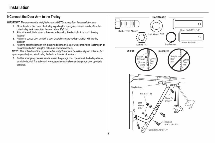
9 Connect the Door Arm to the TrolleyIMPORTANT: The groove on the straight door armMUST face away from the curved door arm.
1. Close the door. Disconnect the trolley by pulling the emergency release handle. Slide theouter trolley back (away from the door) about 2" (5 cm).
2. Attach the straight door arm to the outer trolley using the clevis pin. Attach with the ringfastener.
3. Attach the curved door arm to the door bracket using the clevis pin. Attach with the ringfastener.
4. Align the straight door armwith the curved door arm. Select two aligned holes (as far apart aspossible) and attach using the bolts, nuts and lock washers.
NOTE: If the holes do not line up, reverse the straight door arm. Select two aligned holes (as farapart as possible) and attach using the bolts, nuts and lock washers.5. Pull the emergency release handle toward the garage door opener until the trolley release
arm is horizontal. The trolley will re-engage automatically when the garage door opener isactivated.
Straight Door Arm Curved
DoorArm
(Groove facing out)
CORRECT
StraightDoorArm
Curved Door Arm
INCORRECT
Clevis Pin 5/16"x1-1/4"
Ring Fastener
Clevis Pin5/16"x1"
Nut 5/16" - 18
Lock Washer5/16"
Hex Bolt 5/16" - 18 x 7/8"
HARDWARE
Hex Bolt 5/16"-18x7/8"
Nut 5/16"-18
Lock Washer 5/16"
Clevis Pin 5/16"x1"
Clevis Pin 5/16"x1-1/4"
Ring Fastener

14
Install the Door Control
1 Install the Door Control
To prevent possible SERIOUS INJURY or DEATH from electrocution:l Be sure power is NOT connected BEFORE installing door control.l Connect ONLY to 12 VOLT low voltage wires.
To prevent possible SERIOUS INJURY or DEATH from a closing garage door:l Install door control within sight of garage door, out of reach of children at a minimum height of
5 feet (1.5 m), and away fromALL moving parts of door.l NEVER permit children to operate or play with door control push buttons or remote control
transmitters.l Activate door ONLY when it can be seen clearly, is properly adjusted, and there are no
obstructions to door travel.l ALWAYS keep garage door in sight until completely closed. NEVER permit anyone to cross
path of closing garage door.
INTRODUCTIONCompatible with MyQ® and Security+ 2.0™ accessories, see page 37. Your garage door opener iscompatible with up to 2 Smart Control Panels or 4 of any other Security+ 2.0™ door controls.NOTE: Older LiftMaster door controls and third party products are not compatible.Install the door control within sight of the door at a minimum height of 5 feet (1.5 m) where small childrencannot reach, and away from the moving parts of the door. For gang box installations it is not necessaryto drill holes or install the drywall anchors. Use the existing holes in the gang box.NOTE: Your productmay look different than the illustrations.
HARDWARE
Screw6ABx1" (2)
Drywall Anchors (2)
Screw6-32x1" (2)
1. Strip 7/16 inch (11 mm) of insulation from one end of the wire and separate the wires.2. Connect one wire to each of the two screws on the back of the door control. The wires can be
connected to either screw.PRE-WIRED INSTALLATIONS: Choose any two wires to connect, note which wires are usedso the correct wires are connected at the garage door opener in a later step.
3. Mark the location of the bottommounting hole and drill a 5/32 inch (4 mm) hole.4. Install the bottom screw, allowing 1/8 inch (3 mm) to protrude from the wall.5. Position the bottom hole of the door control over the screw and slide down into place.6. Lift the push bar up and mark the top hole.7. Remove the door control from the wall and drill a 5/32 inch (4 mm) hole for the top screw.8. Position the bottom hole of the door control over the screw and slide down into place. Attach
the top screw.
7/16" (11 mm) Wall
1 2 3
DRYWALLGANG BOX
6ABx1"
6-32x1"Drywall Anchor
4-5 6
6-32x1"
GANG BOX
8 DRYWALL
6ABx1"
Drywall Anchor
7

15
Install the Door Control
2 Wire the door control to the garage door opener
HARDWARE
Insulated Staple
(Not shown)
PRE-WIRED INSTALLATIONS:When wiring the door control to the garage door opener make sure youuse the same wires that are connected to the door control.
1. Run the white and red/white wire from the door control to the garage door opener. Attach thewire to the wall and ceiling with the staples (not applicable for gang box or pre-wiredinstallations). Do not pierce the wire with the staple as thismay cause a short or an opencircuit.
2. Strip 7/16 inch (11 mm) of insulation from the end of the wire near the garage door opener.3. Connect the wire to the red and white terminals on the garage door opener. To insert or
release wires from the terminal, push in the tab with screwdriver tip.
7/16" (11 mm) 2
3
1
Staple
RED
WH
ITE
WH
ITE
GR
EY
3 Attach the warning labels1. Attach the entrapment warning label on the wall near the door control with tacks or staples.2. Attach the manual release/safety reverse test label in a visible location on the inside of the
garage door.

16
Install the Protector System®
Introduction
Be sure power is NOT connected to the garage door opener BEFORE installing the safety reversingsensor.To prevent SERIOUS INJURY or DEATH from closing garage door:
l Correctly connect and align the safety reversing sensor. This required safety device MUSTNOT be disabled.
l Install the safety reversing sensor so beam is NO HIGHER than 6" (15 cm) above garagefloor.
IMPORTANT INFORMATIONABOUTTHE SAFETY REVERSING SENSORSThe safety reversing sensors must be connected and aligned correctly before the garage dooropenerwillmove in the down direction.The sending sensor (with an amber LED) transmits an invisible light beam to the receiving sensor (with agreen LED). If an obstruction breaks the light beamwhile the door is closing, the door will stop andreverse to the full open position, and the garage door opener lights will flash 10 times.NOTE: For energy efficiency the garage door opener will enter sleep mode when the door is fullyclosed. The sleep mode shuts the garage door opener down until activated. The sleep mode issequenced with the garage door opener light bulb; as the light bulb turns off the sensor LEDswill turn offand whenever the garage door opener lights turn on the sensor LEDswill light. The garage door openerwill not go into the sleep mode until the garage door opener has completed 5 cycles upon power up.When installing the safety reversing sensors check the following:
l Sensors are installed inside the garage, one on either side of the door.l Sensors are facing each other with the lenses aligned and the receiving sensor lens does not
receive direct sunlight.l Sensors are no more than 6 inches (15 cm) above the floor and the light beam is
unobstructed.
Invisible Light BeamProtection Area
Safety Reversing Sensor6" (15 cm) max. above floor
Safety Reversing Sensor6" (15 cm) max. above floor

17
Install the Protector System®
1 Install the Safety Reversing SensorsHARDWARE
Carriage Bolt1/4"-20x1/2"
Wing Nut1/4"-20
The safety reversing sensors can be attached to the door track, the wall, or the floor. If the door track willnot support the sensor bracket a wall installation is recommended. Choose one of the followinginstallations.
OPTION A DOORTRACK INSTALLATION1. Slide the curved arms of the sensor bracket around the edge of the door track. Snap into place
so that the sensor bracket is flush against the track.2. Slide the carriage bolt into the slot on each sensor.3. Insert the bolt through the hole in the sensor bracket and attach with the wing nut. The lenses
on both sensors should point toward each other. Make sure the lens is not obstructed by thesensor bracket.
No morethan 6 inches(15 cm) Carriage Bolt
1/4"-20x1/2" Wing Nut1/4"-20
1 2 3
OPTION BWALL INSTALLATIONIf additional clearance is needed an extension bracket (not provided) or wood blocks can be used.Makesure each bracket has the same amount of clearance so they will align correctly.
1. Position the sensor bracket against the wall with the curved arms facing the door.Make surethere is enough clearance for the beam to be unobstructed.Mark holes.
2. Drill 3/16 inch pilot holes for each sensor bracket and attach the sensor brackets to the wallusing lag screws (not provided).
3. Slide the carriage bolt into the slot on each sensor.4. Insert the bolt through the hole in the sensor bracket and attach with the wing nut. The lenses
on both sensors should point toward each other. Make sure the lens is not obstructed by thesensor bracket.
(Not provided)
No more than 6 inches (15 cm)
1 2Inside
Garage
Wall
(Not provided)
LensCarriage Bolt1/4"-20x1/2"
Wing Nut1/4"-20
3 4

18
Install the Protector System®
OPTION C FLOOR INSTALLATIONUse an extension bracket (not provided) or wood block to raise the sensor bracket if needed.
1. Carefully measure the position of both sensor brackets so they will be the same distance fromthe wall and unobstructed.
2. Attach the sensor brackets to the floor using concrete anchors (not provided).3. Slide the carriage bolt into the slot on each sensor.4. Insert the bolt through the hole in the sensor bracket and attach with the wing nut. The lens on
both sensors should point toward each other. Make sure the lens is not obstructed by thesensor bracket.
Inside
Garage
Wall
(Not provided)1 2
Carriage Bolt
1/4"-20x1/2"
Wing Nut
1/4"-20
3 4
2 Wire the Safety Reversing SensorsPRE-WIRED INSTALLATIONS: If your garage already haswires installed for the safety reversingsensors, see page 18.
HARDWARE
Insulated Staple
(Not shown)
OPTION A INSTALLATION WITHOUT PRE-WIRING1. Run the wire from both sensors to the garage door opener. Attach the wire to the wall and
ceiling with the staples.2. Strip 7/16 inch (11 mm) of insulation from each set of wires. Separate the wires. Twist the white
wires together. Twist the white/black wires together.3. Insert the white wires into the white terminal on the garage door opener. Insert the white/black
wires into the grey terminal on the garage door opener. To insert or remove the wires from theterminal, push in the tab with a screwdriver tip.
Staple
1 2
3
7/16" (11 mm)
RED
WH
ITE
WH
ITE
GR
EY
DR
ED
WRE
WH
ITE
WH
ITE
GR
EY
GR
EY

19
Install the Protector System®
OPTION B PRE-WIRED INSTALLATION1. Cut the end of the safety reversing sensor wire,making sure there is enough wire to reach the
pre-installed wires from the wall.2. Separate the safety reversing sensor wires and strip 7/16 inch (11 mm) of insulation from each
end. Choose two of the pre-installed wires and strip 7/16 inch (11 mm) of insulation from eachend.Make sure that you choose the same color pre-installed wires for each sensor.
3. Connect the pre-installed wires to the sensor wires with wire nutsmaking sure the colorscorrespond for each sensor. For example, the white wire would connect to the yellowwire andthe white/black wire would connect to the purple wire.
4. At the garage door opener, strip 7/16 inch (11 mm) of insulation from each end of the wirespreviously chosen for the safety reversing sensors. Twist the like-colored wires together.
5. Insert the wires connected to the white safety sensor wires to the white terminal on the garagedoor opener. Insert the wires that are connected to the white/black safety sensor wires to thegrey terminal on the garage door opener.
Safety reversing sensor wires
Pre-installed wires
WhiteWhite/Black
Yellow (for example)
Purple (for example)
Not Provided
Pre-installed wires Safety reversing sensor wires
7/16"(11 mm)
Yellow
Purple
1
3
4
7/16" (11 mm)
2
Yellow(for example)
Purple(for example)
To insert or remove the wires from the terminal, push in the tab with a screwdriver tip.
5
RED
WH
ITE
WH
ITE
GR
EY
DR
ED
WRE
WH
ITE
WH
ITE
GR
EY
GR
EY

20
Power
1 Connect Power
To prevent possible SERIOUS INJURY or DEATH from electrocution or fire:l Be sure power is NOT connected to the opener, and disconnect power to circuit BEFORE
removing cover to establish permanent wiring connection.l Garage door installation and wiring MUST be in compliance with ALL local electrical and
building codes.l NEVER use an extension cord, 2-wire adapter, or change plug in ANY way to make it fit
outlet. Be sure the opener is grounded.
To avoid installation difficulties, do not activatethe garage door opener at this time.To reduce the risk of electric shock, your garagedoor opener has a grounding type plug with a thirdgrounding pin. This plug will only fit into agrounding type outlet. If the plug doesn’t fit into youroutlet, contact a qualified electrician to install theproper outlet.
THERE ARE TWO OPTIONS FORCONNECTING POWER:
OPTION A TYPICAL WIRING
1. Plug in the garage door opener into agrounded outlet.
2. DO NOT run garage door opener at thistime.
TYPICAL WIRING
OPTION B PERMANENT WIRINGIf permanent wiring is required by your local code, refer to the following procedure. To make apermanent connection through the 7/8 inch hole in the top of the motor unit (according to local code):
Wiring through a filter board (8550 models manufacturedbefore April 12, 2013):
1. Be sure power is NOT connected to the opener,and disconnect power to circuit.
2. Remove the garage door opener cover and setaside.
3. Remove the attached green ground terminal.4. Cut black and white wires. Strip away 1/2 inch (1
cm) of insulation, 3 inches (7.5 cm) before spadeterminals.
5. Remove the power cord from opener.6. Install a conduit or flex cable adapter to the 7/8 inch
hole.7. Run wires through conduit, cut to proper length and
strip insulation.8. Attach with wire nuts provided. Attach the ground
wire to the green ground screw. The opener mustbe grounded.
9. Properly secure wire under plastic ties so that wiredoes not come in contact with moving parts.
10. Reinstall the cover. DO NOT run garage dooropener at this time.
Ground Tab
Green Ground
Screw
Ground Wire
Black Wire
White Wire
PERMANENT WIRING
Wire Nuts
Wiring through a terminal block (8550 modelsmanufactured after April 12, 2013 and all 8557 models):
1. Remove the motor unit cover screws and set thecover aside.
2. Remove the attached 3-prong cord.3. Connect the black (line) wire to the screw on the
brass terminal; the white (neutral) wire to the screwon the silver terminal; and the ground wire to thegreen ground screw.The openermust begrounded.
4. Reinstall the cover.
Ground Tab
Green
Ground
Screw
Ground
Wire
White Wire
PERMANENT WIRING
Black
Wire
Black
Wire

21
Power
2 Ensure the Safety Reversing Sensors are AlignedThe doorwill not close if the sensors have not been installed and aligned correctly.When the light beam is obstructed or misaligned while the door is closing, the door will reverse and thegarage door opener lights will flash ten times. If the door is already open, it will not close. The sensorscan be aligned by loosening the wing nuts, aligning the sensors, and tightening the wing nuts.
1. Check to make sure the LEDs in both sensors are glowing steadily. The LEDs in both sensorswill glow steadily if they are aligned and wired correctly.
Green LEDAmber LED
If the receiving sensor is in direct sunlight, switch it with sending sensor so it is on the opposite side of the door.
(invisible light beam)
SENDING SENSOR RECEIVING SENSOR
IF THE AMBERLEDONTHE SENDING SENSOR IS NOTGLOWING:1. Make sure there is power to the garage door opener.2. Make sure the sensor wire is not shorted/broken.3. Make sure the sensor has been wired correctly:White wires to white terminal and white/black
wires to gray terminal.
RE
D
WH
ITE
WH
ITE
GR
EY
321
IF THE GREEN LED ON THE RECEIVING SENSOR IS NOT GLOWING:1. Make sure the sensor wire is not shorted/broken.2. Make sure the senors are aligned.
1 2
3 Ensure the Door Control is Wired CorrectlyIf the door control has been installed and wired correctly a message will display on the screen.

22
Adjustments
Introduction
Without a properly installed safety reversal system, persons (particularly small children) could beSERIOUSLY INJURED or KILLED by a closing garage door.
l Incorrect adjustment of garage door travel limits will interfere with proper operation ofsafety reversal system.
l After ANY adjustments are made, the safety reversal systemMUST be tested. Door MUSTreverse on contact with 1-1/2" (3.8 cm) high object (or 2x4 laid flat) on floor.
To prevent damage to vehicles, be sure fully open door provides adequate clearance.
Your garage door opener is designed with electronic controls to make setup and adjustments easy. Theadjustments allow you to programwhere the door will stop in the open (UP) and close (DOWN) position.The electronic controls sense the amount of force required to open and close the door. The force isadjusted automatically when you program the travel.NOTE: If anything interferes with the door’s upward travel it will stop. If anything interferes with the door’sdownward travel, it will reverse.
UP (Open) DOWN (Close)
PROGRAMMING BUTTONSThe programming buttons are located on the left side panel of the garage door opener and are used toprogram the travel.While programming, the UP and DOWNbuttons can be used to move the door asneeded.
UP Button
Adjustment Button
DOWN Button
PROGRAMMING BUTTONS
To watch a short instructional video on programming your new garage door opener use yoursmartphone to read the QRCode below:

23
Adjustments
1 Program the Travel
Without a properly installed safety reversal system, persons (particularly small children) could beSERIOUSLY INJURED or KILLED by a closing garage door.
l Incorrect adjustment of garage door travel limits will interfere with proper operation ofsafety reversal system.
l After ANY adjustments are made, the safety reversal systemMUST be tested. Door MUSTreverse on contact with 1-1/2" (3.8 cm) high object (or 2x4 laid flat) on floor.
While programming, the UP and DOWNbuttons can be used to move the door as needed.1. Press and hold the Adjustment Button until the UP Button begins to flash and/or a beep is
heard.2. Press and hold the UP Button until the door is in the desired UP position.3. Once the door is in the desired UP position press and release the Adjustment Button. The
garage door opener lights will flash twice and the DOWNButton will begin to flash.4. Press and hold the DOWNButton until the door is in the desired DOWNposition.5. Once the door is in the desired DOWNposition press and release the Adjustment Button. The
garage door opener lights will flash twice and the UP Button will begin to flash.6. Press and release the UP Button.When the door travels to the programmed UP position, the
DOWNButton will begin to flash.7. Press and release the DOWNButton. The door will travel to the programmed DOWNposition.
Programming is complete.If the garage door opener lights are flashing 5 times during the steps for Program the Travel, theprogramming has timed out. If the garage door opener lights are flashing 10 times during the steps forProgram the Travel, the safety reversing sensors are misaligned or obstructed (refer to page 21).Whenthe sensors are aligned and unobstructed, cycle the door through a complete up and down cycle usingthe remote control or the UP and DOWNbuttons. Programming is complete. If you are unable to operatethe door up and down, repeat the steps for Programming the Travel.
UP Button
Adjustment Button
DOWN Button
PROGRAMMING BUTTONS
1 2 3
4 5
6 7

24
Adjustments
2 Test the Safety Reversal System
Without a properly installed safety reversal system, persons (particularly small children) could beSERIOUSLY INJURED or KILLED by a closing garage door.
l Safety reversal systemMUST be tested everymonth.l After ANY adjustments are made, the safety reversal systemMUST be tested. Door MUST
reverse on contact with 1-1/2" (3.8 cm) high object (or 2x4 laid flat) on the floor.
1. With the door fully open, place a 1-1/2 inch (3.8 cm) board (or a 2x4 laid flat) on the floor,centered under the garage door.
2. Press the remote control push button to close the door. The door MUST reverse when it makescontact with the board.
If the door stops and does not reverse on the obstruction, increase the down travel (refer to AdjustmentStep 1). Repeat the test.When the door reverses upon contact with the 1-1/2 inch board, remove theboard and open/close the door 3 or 4 times to test the adjustment. If the garage door opener continues tofail the safety reversal test, call a trained door systems technician.
1 2
3 Test the Protector System®
Without a properly installed safety reversing sensor, persons (particularly small children) could beSERIOUSLY INJURED or KILLED by a closing garage door.
1. Open the door. Place the garage door opener carton in the path of the door.2. Press the remote control push button to close the door. The door will notmove more than an
inch (2.5 cm), and the garage door opener lights will flash 10 times.The garage door opener will not close from a remote control if the LED in either safety reversing sensoris off (alerting you to the fact that the sensor ismisaligned or obstructed). If the garage door openercloses the door when the safety reversing sensor is obstructed (and the sensors are no more than6 inches [15 cm] above the floor), call for a trained door systems technician.
1 2

25
Battery Backup*
1 Install the Battery
To reduce the risk of FIRE or INJURY to persons:l Disconnect ALL electric and battery power BEFORE performing ANY service or
maintenance.l Use ONLY LiftMaster part # 485LM for replacement battery.l DO NOT dispose of battery in fire. Batterymay explode. Checkwith local codes for
disposal instructions.
ALWAYS wear protective gloves and eye protection when changing the battery or workingaround the battery compartment.
1. Unplug the garage door opener.2. Open the light lens on the right side panel of the garage door opener. Use a Phillips head
screwdriver to remove the battery cover on the garage door opener.3. Partially insert the battery into the battery compartment with the terminals facing out.4. Connect red (+) and black (-) wires from the garage door opener to the corresponding
terminals on the battery.5. Replace the battery cover.6. Plug in the garage door opener.7. Wait for the green Battery Status LED to start flashing before proceeding to test the battery.
Battery
Status LED
* If applicable.
2 Test the Battery1. Unplug the garage door opener. The battery status LEDwill either glow solid orange
indicating opener is operating on battery power or will flash indicating low battery power.NOTE:Make sure the garage door opener is unplugged.
2. Open and close the door using the remote control or door control.NOTE: The garage door opener may run slower if the battery is not fully charged. The batterywill take 24 hours to fully charge.
3. Plug in the garage door opener. Verify the battery status LED flashing green, indicating thebattery is charging.
1 2 3

26
Battery Backup*
Charge the BatteryThe battery charges when the garage door opener is plugged into a 110Vac electrical outlet that haspower and requires 24 hours to fully charge. A fully charged battery supplies 12Vdc to the garage dooropener for one to two days of normal operation during an electrical power outage. After the electricalpower has been restored, the battery will recharge within 24 hours. The battery will last approximately 1to 2 years with normal usage. Instructions for replacement are provided with the battery. To obtainmaximum battery life and prevent damage, disconnect the battery when the garage door opener isunplugged for an extended period of time, such as a summer or winter home.NOTE: When the garage door opener is in battery backup mode the garage door opener lights, Timer-to-Close, and Remote Close features are unavailable.
* If applicable, part number 485LM.
Battery Status LEDGREENLED:All systems are normal.
l A solid green LED light indicates the battery is fully charged.l A flashing green LED indicates the battery is being charged.
ORANGE LED:The garage door opener has lost power and is in battery backup mode.
l A solid orange LEDwith beep, sounding approximately every 2 seconds, indicates the garagedoor opener is operating on battery power.
l A flashing orange LEDwith beep, sounding every 30 seconds, indicates the battery is low.REDLED:The garage door opener's 12V battery needs to be replaced.
l A solid red LEDwith beep, sounding every 30 seconds, indicates the 12V battery will nolonger hold a charge and needs to be replaced. Replace the battery back up to maintain thebattery backup feature.
NOTE: The Battery Status LED ismost visible with the garage door opener light off. Battery does nothave to be fully charged to operate the garage door opener.
Battery Status LED

27
IMPORTANT SAFETY INSTRUCTIONS
WARNING
To reduce the risk of SEVERE INJURY or DEATH:1. READANDFOLLOWALL WARNINGS AND INSTRUCTIONS.2. ALWAYS keep remote controls out of reach of children. NEVER permit children to operate or
play with garage door control push buttons or remote controls.3. ONLY activate garage door when it can be seen clearly, it is properly adjusted, and there are
no obstructions to door travel.4. ALWAYS keep garage door in sight and away from people and objects until completely
closed. NO ONE SHOULDCROSS THE PATHOFTHE MOVING DOOR.5. NO ONE SHOULDGO UNDERA STOPPED, PARTIALLY OPENEDDOOR.6. If possible, use emergency release handle to disengage trolleyONLY when garage door is
CLOSED.Use caution when using this release with the door open.Weak or broken springs orunbalanced door could result in an open door falling rapidly and/or unexpectedly andincreasing the risk of SEVERE INJURY or DEATH.
7. NEVER use emergency release handle unless garage doorway is clear of persons andobstructions.
8. NEVER use handle to pull garage door open or closed. If rope knot becomes untied, youcould fall.
9. After ANY adjustments are made, the safety reversal systemMUST be tested.
10. Safety reversal systemMUST be tested everymonth. Garage door MUST reverse oncontact with 1-1/2" (3.8 cm) high object (or a 2x4 laid flat) on the floor. Failure to adjust thegarage door opener properly increases the risk of SEVERE INJURY or DEATH.
11. ALWAYS KEEP GARAGE DOORPROPERLY BALANCED (see page 2). An improperlybalanced door mayNOT reverse when required and could result in SEVERE INJURY orDEATH.
12. ALL repairs to cables, spring assemblies and other hardware, ALL of which are underEXTREME tension,MUST be made by a trained door systems technician.
13. To avoid SERIOUS PERSONAL INJURY or DEATH from electrocution, disconnect ALLelectric and battery power BEFORE performing ANY service or maintenance.
14. This operator system is equipped with an unattended operation feature. The door couldmove unexpectedly. NO ONE SHOULDCROSS THE PATHOFTHE MOVING DOOR.
15. DO NOT enable the Timer-to-Close functionality if operating either one-piece or swinginggarage doors. To be enabled ONLY when operating a sectional door.
16. SAVE THESE INSTRUCTIONS.
Operation

28
Features
Your garage door opener is equipped with features to provide you with greater control over your garagedoor operation.Alert2CloseThe Alert2Close feature provides a visual and an audible alert that an unattended door is closing.TIMER-TO-CLOSE (TTC)The TTC feature automatically closes the door after a specified time period that can be adjusted using aTTC enabled door control (Models 881LM or 880LM). Prior to and during the door closing the garagedoor opener lights will flash and the garage door opener will beep.MyQ®
MyQ® technology uses a 900MHz signal to provide two-way communication between the garage dooropener and MyQ® enabled accessories. Your garage door opener is compatible with up to 16 MyQ®
accessories.SECURITY+ 2.0™ REMOTE CONTROLS ANDDOORCONTROLSYour garage door opener has already been programmed at the factory to operate with your remotecontrol, which changeswith each use, randomly accessing over 100 billion new codes. Compatible withMyQ® and Security+ 2.0™ accessories, see page 37.NOTE: Older LiftMaster remote controls, door controls, and third party products are not compatible.
SECURITY+ 2.0TM
AccessoriesMemory Capacity
Remote Controls Up to 40
DoorControls Up to 2 Smart Control Panels or 4 of any other Security+ 2.0™ door controls
Keyless Entries Up to 4
THE PROTECTORSYSTEM® (SAFETY REVERSING SENSORS)When properly connected and aligned, the safety reversing sensors will detect an obstruction in the pathof the infrared beam. If an obstruction breaks the infrared beamwhile the door is closing, the door willstop and reverse to full open position, and the opener lights will flash 10 times. If the door is fully open,and the safety reversing sensors are not installed, or are misaligned, the door will not close from aremote control. However, you can close the door if you hold the button on the door control or keylessentry until the door is fully closed. The safety reversing sensors do not affect the opening cycle.
ENERGY CONSERVATIONFor energy efficiency the garage door opener will enter sleep mode when the door is fully closed. Thesleep mode shuts the garage door opener down until activated. The sleep mode is sequenced with thegarage door opener light bulb; as the light bulb turns off the sensor LEDswill turn off and whenever thegarage door opener lights turn on the sensor LEDswill light. The garage door opener will not go into thesleep mode until the garage door opener has completed 5 cycles upon power up.LIGHTSThe garage door opener light bulbs will turn on when the opener is initially plugged in; power is restoredafter interruption, or when the garage door opener is activated. The lights will turn off automatically after4-1/2 minutes. An incandescent A19 light bulb (100 watt maximum) or for maximum energy efficiency a26W (100W equivalent) compact fluorescent light (CFL) bulb may be used.Light FeatureThe garage door opener is equipped with an added feature; the lights will turn on when someone entersthrough the open garage door and the safety reversing sensor infrared beam is broken. For addedcontrol over the light bulbs on your garage door opener, see page 29.USING YOURGARAGE DOOROPENERThe garage door opener can be activated through a wall-mounted door control, remote control, wirelesskeyless entry or MyQ® accessory.When the door is closed and the garage door opener is activated thedoor will open. If the door senses an obstruction or is interrupted while opening the door will stop.Whenthe door is in any position other than closed and the garage door opener is activated the door will close.If the garage door opener senses an obstruction while closing, the door will reverse. If the obstructioninterrupts the sensor beam the garage door opener lights will blink 10 times. However, you can close thedoor if you hold the button on the door control or keyless entry until the door is fully closed. The safetyreversing sensors do not affect the opening cycle. The safety reversing sensor must be connected andaligned correctly before the garage door opener will move in the down direction.BATTERY BACKUP*The battery backup system allows access in and out of your garage, even when the power is out.Whenthe garage door opener is operating on battery power, the garage door opener will run slower, the lightwill not function, the Battery Status LEDwill glow solid orange, and a beep will sound approximatelyevery 2 seconds.* If applicable.

29
Door Control
Using the Door Control
SYNCHRONIZE THE DOOR CONTROL
To synchronize the door control to the garage door opener, press the push bar until the garage dooropener activates (it may take up to 3 presses). Test the door control by pressing the push bar, eachpress of the push bar will activate the garage door opener.
Push Bar
LIGHT button
Screen
Motion Sensor
Navigation Buttons
PUSHBARPress the push bar to open or close the door.
NAVIGATIONBUTTONSUse the navigation buttons to make selections and program features.
LIGHTBUTTONPress the LIGHT button to turn the garage door opener lights on or off.When the lights are turned onthey will stay on until the LIGHT button is pressed again, or until the garage door opener is activated.Once the garage door opener is activated the lights will turn off after the specified period of time (thefactory setting is 4-1/2 minutes). The LIGHT button will not control the lights when the door is in motion.SCREENThe screen will display the time and temperature until the menu button is pressed, and then it will displaythe menu options. If there is a problemwith the garage door opener the screen will display the DiagnosticCode. Refer to the Troubleshooting section.
The following features are accessible through the screen using the navigation buttons:LEARNADEVICEAny compatible remote controls, wireless keyless entry, or MyQ® accessories can be programmed to thegarage door opener by accessing the menu and using the navigation buttons.LOCKThe LOCK feature is designed to prevent activation of the garage door opener from remote controlswhile still allowing activation from the door control and keyless entry. This feature is useful for addedpeace ofmind when the home is empty (i.e. vacation).
TIMER-TO-CLOSE (TTC)DO NOT enable TTC if operating a one-piece door. TTC is to be used ONLY with sectional doors.Factory default is set to off. TTC can be set to automatically close your garage door from the fully openposition after a specified period of time (1, 5, 10 minute intervals or a custom setting up to 99 minutes).The garage door opener will Beep and the lights will Flash before closing the door. The screen on thedoor control can display the status of the TTC. TTCWILL NOTwork if the garage door opener isoperating by battery power or if the safety reversing sensors are misaligned. This feature is NOTintended to be the primarymethod of closing the door.A keyless entry should be installed in the eventof an accidental lock out when using this feature.NOTE: Before enabling the TTC for the first time, or if you experience a power outage, cycle the garagedoor opener open and closed to allow the TTC to set.
AUTOMATIC LIGHTMotion SensorFactory default is set to on. This feature automatically turns on the garage door opener lights whenmotion is sensed. The lights will come on for the set period of time, then shut off. If using the garage dooropener light as a work light disable the motion sensor, otherwise the light will turn off automatically if youare beyond the range of the sensor.Light FeatureThe lights will turn on when someone enters through the open garage door and the safety reversingsensor infrared beam is broken.
MAINTENANCE ALERT (MAS)This feature assists the homeowner in ensuring the garage door opener system stays in good workingcondition.When the garage door opener needs to be serviced (approximately 4500 garage dooropener cycles) the command (yellow) and service (red) LEDswill begin to alternately flash back andforth. The factory setting for the MAS feature is off and can be activated at time of installation. Contact yourinstalling dealer for service.

30
Door Control
Smart Control Panel SetupThe features on the door control can be programmed through a series ofmenus on the screen and thenavigation buttons. Refer to the descriptions below.
SCREENThe main screen displays the time, temperature, and current battery charge (if applicable)
Navigation Buttons
FEATURESPress the navigation button below "MENU" to view the Featuresmenu.
Set the time, choose 12 or 24 hour clock and show/hide clock.
For sectional doors ONLY. Set the Timer-to-Close feature off/on
and set the time interval before door closes. NOTE: DO NOT
enable TTC if operating a one-piece door. TTC is to be used
ONLY with sectional doors.
Enable/disable lock.
Add remote controls, MyQ® devices, an extra remote button
to control your garage door opener lights, or a keyless entry.
SETTINGSPress the navigation button below the down arrow till you see TEMPERATURE to view the Settingsmenu.
Display the temperature in Fahrenheit or Celsius and show/hide the temperature.
Select a language.
Set duration for garage door opener light to stay on after operation, selectable range of 1-1/2 to 4-1/2 minutes. Turn the Motion sensor off/on, and turn the entry light feature off/on.
Adjust the contrast of the screen.
SERVICEPress and hold the second navigation button, then press the LIGHT button to view the Service menu.
Displays software version information.
Turn the Maintenance Alert (MAS) on/off.
Displays the number of remote controls, MyQ® devices,
door controls and keyless entries currently programmed
to operate the garage door opener.
Displays any errors that have occurred.
To program a remote control or keyless entry to the garage door opener using the door control, seepage 31.

31
Remote Control
Your remote control has been programmed at the factory to operate with your garage door opener.Older LiftMaster remote controls are NOT compatible, see page 37 for compatible accessories.Programming can be done through the door control or the learn button the garage door opener. Toprogram additional accessories refer to the instructions provided with the accessory or visitwww.LiftMaster.com. If your vehicle is equipped with a Homelink®, you may require an external adapterdepending on the make,model, and year of your vehicle. Visit www.homelink.com for additionalinformation.TO ADD,REPROGRAM,ORCHANGE AREMOTE CONTROL/KEYLESS ENTRY PINUSING THEDOORCONTROL
1. Press the navigation button below "MENU" to view the Featuresmenu.2. Use the navigation buttons to scroll to "PROGRAM".3. Select "REMOTE" or "KEYPAD" to program from the programmenu.4. Remote Control:
Press the button on the remote control that you wish to operate your garage door.Keyless Entry:Enter a 4-digit personal identification number (PIN) of your choice on the keyless entrykeypad. Then press the ENTER button.
The garage door opener lights will flash (or two clicks will be heard) when the code has beenprogrammed. Repeat the steps above for programming additional remote controls or keyless entrydevices. If programming is unsuccessful, program the remote using the learn button.
Press to continue.
TO REMOTE
Press to continue.1 2 3
OR
PIN
? ? ? ?
4GHI 5JKL
7PRS 8TUV 9WXY
0 QZ* #
ENTER
0 QZ*
#
ENTER
6 MNO4

32
Remote Control
PROGRAMAREMOTE CONTROLUSING THE LEARNBUTTONONTHE GARAGE DOOROPENER1. Locate the Learn button on the garage door opener.
NOTE: Your garage door opener may look different.2. Locate the ProgramButton on the side of the remote control.3. Using a safety pin or paper clip, press the program button until the LEDs on the front of the
remote control turn on.4. Press and release the Learn button on the garage door opener. The Learn LED will light.
Within 30 seconds...5. Press and release the remote control button you want to use. Check to see if the garage door
opener light bulb blinks. If not, wait for the remote control LED to light solid then slowly pressand release the remote control button again.Repeat until the light bulb blinks.DO NOT pressthe button after the light bulb blinks.
6. To exit programming mode, press any remote control button except the button that was justprogrammed.
7. To test, press the programmed button on the remote control... The garage door opener willactivate.
1
2 3 4
5
7
6
Learn
DEL
Yellow
Program Button
To Erase the MemoryERASE ALLREMOTE CONTROLS ANDKEYLESS ENTRIES
1. Press and hold the learn button on garage door opener until the learn LED goes out(approximately 6 seconds). All remote control and keyless entry codes are now erased.
Reprogram any accessory you wish to use.
ERASE ALLDEVICES (IncludingMyQ® enabled accessories)1. Press and hold the learn button on garage door opener until the learn LED goes out
(approximately 6 seconds).2. Immediately press and hold the learn button again until the learn LED goes out. All codes are
now erased.Reprogram any accessory you wish to use.

33
To Open the Door Manually
To Open the Door Manually
To prevent possible SERIOUS INJURY or DEATH from a falling garage door:l If possible, use emergency release handle to disengage trolleyONLY when garage door is
CLOSED.Weak or broken springs or unbalanced door could result in an open door fallingrapidly and/or unexpectedly.
l NEVER use emergency release handle unless garage doorway is clear of persons andobstructions.
l NEVER use handle to pull door open or closed. If rope knot becomes untied, you could fall.
DISCONNECTTHE TROLLEY1. The door should be fully closed if possible.2. Pull down on the emergency release handle.
RECONNECTTHE TROLLEYThe lockout feature prevents the trolley from reconnecting automatically.
1. Pull the emergency release handle down and back (toward the opener). The door can thenbe raised and lowered manually as often as necessary.
2. To disengage the lockout feature, pull the handle straight down. The trolley will reconnect onthe next UP or DOWNoperation, either manually or by using the door control or remotecontrol.
NOTICE
NOTICE

34
Maintenance
Maintenance ScheduleEVERY MONTH
l Manually operate door. If it is unbalanced or binding, call a trained door systems technician.l Check to be sure door opens and closes fully. Adjust if necessary, see page 23.l Test the safety reversal system. Adjust if necessary, see page 24.
EVERY YEARl Oil door rollers, bearings and hinges. The garage door opener does not require additional
lubrication. Do not grease the door tracks.l Test the battery (if applicable) and consider replacing the battery to ensure the garage door
opener will operate during an electrical power outage, see page 25 to test the battery backup.EVERY TWO TO THREE YEARS
l Use a rag to wipe away the existing grease from the garage door opener rail. Reapply a smalllayer of white lithium grease to the top and underside of the rail surface where the trolleyslides.
The Remote Control Battery
To prevent possible SERIOUS INJURY or DEATH:l NEVER allow small children near batteries.l If battery is swallowed, immediately notify doctor.
To reduce risk of fire, explosion or chemical burn:l Replace ONLY with 3V CR2016 coin batteries.l DO NOT recharge, disassemble, heat above 212°F (100°C) or incinerate.
Batteries
Screws (2)
To replace the batteries, remove the two screws and open the remotecontrol housing. Push the battery out of the holder for removal. Insertreplacement batteries positive side up (+).Replace the batteries with only 3V CR2016 coin cell batteries. Dispose ofold batteries properly.
NOTICE: To complywith FCC and/or IndustryCanada (IC) rules, adjustment ormodificationsof this transceiverare prohibited. THEREARENOUSERSERVICEABLEPARTS.Thisdevice complieswith Part 15 of the FCC rules and ICRSS-210. Operation is subject to the following two conditions: (1) thisdevicemaynot cause harmfulinterference, and (2) thisdevice must accept any interference received, including interference that maycauseundesired operation.ThisClassBdigitalapparatuscomplieswith Canadian ICES-003.
AVIS: Lesrèglesde la FCC et/ou d’Industrie Canada (IC) interdisent tout ajustement ou toute modification de ce récepteur. ILN’EXISTEAUCUNEPIÈCESUSCEPTIBLED’ÊTREENTRETENUEPAR L’UTILISATEUR.Cet appareilest conforme auxdispositionsde la partie 15 du règlement de la FCC et de l'norme IC RSS-210. Son utilisation estassujettie auxdeuxconditoinssuivantes: (1)ce dispositif ne peut causerdesinterférencesnuisibles, et (2)ce dispositif doit acceptertoute interférence recue, ycomprisune interférence pouvant causerun fonctionnement non souhaité.Cet appareilnumerique de la classe Best conforme a la norme NMB-003 du Canada.

35
Your garage door opener is programmed with self-diagnostic capabilities. The UP and DOWNarrows on the garage door opener flash the diagnostic codes.
DIAGNOSTICCODE SYMPTOM SOLUTION
Up ArrowFlash(es)
Down ArrowFlash(es)
1 1 The garage door opener will not close and the lightbulbs flash.
Safety sensors are not installed, connected or wiresmay be cut. Inspect sensor wires for adisconnected or cut wire.
1 2 The garage door opener will not close and the lightbulbs flash.
There is a short or reversed wire for the safety sensors. Inspect safety sensor wire at all staple pointsand connection points and replace wire or correct as needed.
1 3 The door control will not function. The wires for the door control are shorted or the door control is faulty. Inspect safety sensor wire at allstaple points and connection points and replace wire or correct as needed.
1 4 The garage door opener will not close and the lightbulbs flash.
Safety sensors are misaligned or were momentarily obstructed. Realign both sensors to ensure bothLEDs are steady and not flickering.Make sure nothing is hanging or mounted on the door that wouldinterrupt the sensors path while closing.
1 5 Door moves 6-8" stops or reverses. Manually open and close the door. Check for binding or obstructions, such as a broken spring ordoor lock, correct as needed. Checkwiring connections at travel module and at the logic board.Replace travel module if necessary.
No movement, only a single click. Manually open and close the door. Check for binding or obstructions, such as a broken spring ordoor lock, correct as needed. Replace logic board if necessary.
Opener hums for 1-2 seconds no movement. Manually open and close the door. Check for binding or obstructions, such as a broken spring ordoor lock, correct as needed. Replace motor if necessary.
1 6 Door coast after it has come to a complete stop. Program travel to coasting position or have door balanced by a trained technician.
2 1-5 No movement or sound. Replace logic board.
3 2 Unable to set the travel or retain position. Check travel module for proper assembly, replace if necessary.
3 3 The battery status LED* is constantly flashing green. Battery backup charging circuit error, replace logic board. *(if applicable)
Troubleshooting

36
DIAGNOSTICCODE SYMPTOM SOLUTION
Up ArrowFlash(es)
Down ArrowFlash(es)
4 1-4 Door ismoving stops and or reverses. Manually open and close the door. Check for binding or obstructions, such as a broken spring ordoor lock, correct as needed. If the door is binding or sticking contact a trained door systemstechnician. If door is not binding or sticking attempt to reprogram travel (refer to page 23).
4 5 Opener runs approximately 6-8", stops and reverses. Communication error to travel module. Check travel module connections, replace module ifnecessary.
4 6 The garage door opener will not close and the lightbulbs flash.
Safety sensors are misaligned or were momentarily obstructed. Realign both sensors to ensure bothLEDs are steady and not flickering.Make sure nothing is hanging or mounted on the door that wouldinterrupt the sensor's path while closing.
The garage door opener can beep for several reasons:l (If applicable) Operating on battery power or the 12 Vdc battery needs to be
replaced, see page 26.l Garage door opener has been activated through a device or feature such as
Timer-to-Close, garage door monitor or MyQ® Internet Gateway, see page 28.My remote control will not activate the garage door:
l Verify the lock feature is not activated on the door control.l Reprogram the remote control.l If the remote control will still not activate the door check the diagnostic codes to
ensure the garage door opener is working properly.My doorwill not close and the light bulbs blink onmy motor unit:
The safety reversing sensor must be connected and aligned correctly before the garagedoor opener will move in the down direction.
l Verify the safety sensors are properly installed, aligned and free of anyobstructions.
My garage door opener light(s) will not turn off when the door is open:The garage door opener is equipped with a feature that turns the light on when the safety reversing sensorshave been obstructed or when the motion sensor on the door control detectsmovement in the garage. Thesefeatures can be disabled using the door control, see page 30.My neighbor’s remote control opens my garage door:Erase the memory from your garage door opener and reprogram the remote control(s).The LEDs on the door control blink:If you have a Smart Control Panel installed and the TTC is set to a custom time, press the ON button on thePremiumMotion-Detecting Control Panel to set the time properly.My vehicle's Homelink® is not programming tomy garage door opener:Depending on the make,model, and year of your vehicle an external adapter may be required. Visitwww.homelink.com for additional information.
Troubleshooting

828LM LiftMaster® Internet Gateway:Internet enabled accessorywhich connects to the computerand allows you to monitor andcontrol garage door openersand lighting accessories enabledbyMyQ® technology.
829LM Garage andGate Monitor:Monitor open/closed status for up to4 MyQ® compatible garage dooropeners or gate operators andclose them from anywhere in thehome.
895MAX 3-Button PremiumMAX Remote Control:Compatible with LiftMaster®
garage door openersmanufactured since 1993.Includes visor clip.
880LM Smart Control Panel®:Displays temperature, time and systemdiagnostics; includes a push bar to openand close the door and a lock feature forextra security. SECURITY+ 2.0™
compatible.
823LM Remote Light Switch:Automatically control your lightsusing your garage door opener,a SECURITY+ 2.0™ remotecontrol or a LiftMaster® InternetGateway. Simply replaces yourcurrent wired wall switch.
990LM Surge Protector:The Garage Door Opener SurgeProtector is designed to protectLiftMaster® garage door openersagainst damage from lightning andpower surges. Easy to install.
893MAX 3-ButtonMAX RemoteControl:Compatible with LiftMaster®
garage door openersmanufactured since 1993.Includes visor clip.
881LM MotionDetectingControl PanelwithTimer-to-Close Control:Multi-function door control with motionsensor that automatically turns opener lightson when it detects a person entering thegarage. SECURITY+ 2.0™ compatible.
825LM Remote Light Control:Automatically control your lightsusing your garage door opener,a SECURITY+ 2.0™ remotecontrol or a LiftMaster®
Internet Gateway. Plugs into anyinterior outlet.
877MAX MAX Wireless Keyless Entry:For use outside of the home toenable access to the garage usinga 4-digit PIN.Works with ALLLiftMaster® openers from 1993-present.
890MAX Mini 3-ButtonMAX RemoteControl:Compatible with LiftMaster®
garage door openersmanufactured since 1993.
886LM MotionDetectingControl Panel:Multi-function door control with motionsensor that automatically turns opener lightson when it detects a person entering thegarage. SECURITY+ 2.0™ compatible.
975LM LaserGarage ParkingAssist:Laser enables homeowners toprecisely park vehicles in thegarage.
892LT/894LT 2 & 4 Button LearningRemoteControls:Compatible with LiftMaster®
garage door openersmanufactured since 1997. Alsocompatible with Encrypted DIPfor gate applications.
485LM 12V Battery for BackupSystem:Provides backup power to the garagedoor opener (if applicable).
Accessories
37

Warranty
LIFTMASTER® FIVE YEAR LIMITED WARRANTYLIFETIME MOTOR AND BELT LIMITED WARRANTY
ONE YEAR LIMITED WARRANTY FOR THE BATTERY BACKUP SYSTEM
LiftMaster (“Seller”) warrants to the fi rst retail purchaser of this product, for the residence in which this product is originally installed, that it is free from defects in materials and/or workmanship for a period of fi ve years from the date of purchase, except that the motor and belt are warranted to be free from defects in materials and/or workmanship for the lifetime of the product while you own your residence, and the Battery Backup System is warranted to be free from defects in materials and/or workmanship for a period of one year from the date of purchase. The proper operation of this product is dependent on your compliance with the instructions regarding installation, operation, and maintenance and testing. Failure to comply strictly with those instructions will void this limited warranty in its entirety.
If, during the limited warranty period, this product appears to contain a defect covered by this limited warranty, call 1- 800-528- 9131, toll free, before dismantling this product. You will be advised of disassembly and shipping instructions when you call. Then send the product or component, pre-paid and insured, as directed to our service center for warranty repair. Please include a brief description of the problem and a dated proof-of-purchase receipt with any product returned for warranty repair. Products returned to Seller for warranty repair, which upon receipt by Seller are confi rmed to be defective and covered by this limited warranty, will be repaired or replaced (at Seller’s sole option) at no cost to you and returned pre- paid. Defective parts will be repaired or replaced with new or factory-rebuilt parts at Seller’s sole option. [You are responsible for any costs incurred in removing and/or reinstalling the product or any component .]
ALL IMPLIED WARRANTIES FOR THE PRODUCT, INCLUDING BUT NOT LIMITED TO ANY IMPLIED WARRANTIES OF MERCHANTABILITY AND FITNESS FOR A PARTICULAR PURPOSE, ARE LIMITED IN DURATION TO THE APPLICABLE LIMITED WARRANTY PERIOD SET FORTH ABOVE FOR THE RELATED COMPONENT(S), AND NO IMPLIED WARRANTIES WILL EXIST OR APPLY AFTER SUCH PERIOD. Some States do not allow limitations on how long an implied warranty lasts, so the above limitation may not apply to you. THIS LIMITED WARRANTY DOES NOT COVER NON-DEFECT DAMAGE, DAMAGE CAUSED BY IMPROPER INSTALLATION, OPERATION OR CARE (INCLUDING, BUT NOT LIMITED TO ABUSE, MISUSE, FAILURE TO PROVIDE REASONABLE AND NECESSARY MAINTENANCE, UNAUTHORIZED REPAIRS OR ANY ALTERATIONS TO THIS PRODUCT), LABOR CHARGES FOR REINSTALLING A REPAIRED OR REPLACED UNIT, REPLACEMENT OF CONSUMABLE ITEMS (E.G., BATTERIES IN REMOTE CONTROL TRANSMITTERS AND LIGHT BULBS), OR UNITS INSTALLED FOR NON-RESIDENTIAL USE. THIS LIMITED WARRANTY DOES NOT COVER ANY PROBLEMS WITH, OR RELATING TO, THE GARAGE DOOR OR GARAGE DOOR HARDWARE, INCLUDING BUT NOT LIMITED TO THE DOOR SPRINGS, DOOR ROLLERS, DOOR ALIGNMENT OR HINGES. THIS LIMITED WARRANTY ALSO DOES NOT COVER ANY PROBLEMS CAUSED BY INTERFERENCE. UNDER NO CIRCUMSTANCES SHALL SELLER BE LIABLE FOR CONSEQUENTIAL, INCIDENTAL OR SPECIAL DAMAGES ARISING IN CONNECTION WITH USE, OR INABILITY TO USE, THIS PRODUCT. IN NO EVENT SHALL SELLER’S LIABILITY FOR BREACH OF WARRANTY, BREACH OF CONTRACT, NEGLIGENCE OR STRICT LIABILITY EXCEED THE COST OF THE PRODUCT COVERED HEREBY. NO PERSON IS AUTHORIZED TO ASSUME FOR US ANY OTHER LIABILITY IN CONNECTION WITH THE SALE OF THIS PRODUCT.
Some states do not allow the exclusion or limitation of consequential, incidental or special damages, so the above limitation or exclusion may not apply to you. This limited warranty gives you specifi c legal rights, and you may also have other rights, which vary from state to state.
38

39
Repair PartsRail Assembly Parts Installation Parts
1
3
4
5
7
6
2
NOTICEUP
CEILING MOUNT ONLY
12
3
4
5
6
7
89
10
Description Part Number
1 Belt - for 7 foot door 41A5434-11
Belt - for 8 foot door 41A5434-13
Belt - for 10 foot door 41A5434-14
2 Belt Pulley Bracket 41B5424
3 Master Link 4A1008
4 One-Piece Rail 7 feet (2.1 m)
2777BD
One-Piece Rail 8 feet (2.4 m)
2778BD
One-Piece Rail 10 feet (3 m)
2770BD
5 Trolley Assembly 41B3869-3A
6 Tensioner Assembly 41B4103
7 Trolley Threaded Shaft 109B48
Not Shown
Owner’s Manual 114A4665
Description Part Number
1 Curved Door Arm 178B35
2 Door Bracket with Clevis Pin and Fastener
41A5047-1
3 Emergency Release Rope and Handle
41A2828
4 Header Bracket with Clevis Pin and Fastener
41A4353-1
5 Remote Control Visor Clip 29C151
6 Safety Sensor Bracket 41A5266-1
7 Safety Sensor KitReceiving and sending sensors with 2-conductor wire
41A5034
8 Straight Door Arm 178B34
9 White and Red/White Wire 41B4494-1
10 3V2016 Lithium Battery 10A19

40
4
10
1
95
3
6
2
78
4 3
Repair Parts Description Part Number
1 Sprocket and Sprocket Cover with Screws
41C589-2
2 End Panel with battery cover and light socket
41D217
3 Light Lens 41A7562
4 Light Socket 41C279
5 Transformer 41A7635
6 Cover 041A7619
7 Motor and Travel Module 41D1739-1
8 Travel Module 41A7114-7
9 End Panel and light socket 41D216
10 Receiver Logic Board 45DCT
Garage Door Opener Parts - MODEL 8550

1
6
2
3
4
5
6
5
7
8
9
10
11
1213
Repair PartsGarage Door Opener Parts - MODEL 8557
© 2014, LiftMaster114A4665B All Rights Reserved
Contact Information
Before calling, please have the model number of the garage door opener. If you are calling about a Troubleshooting issue, it is recommended that you have access to your garage
door opener while calling. If you are ordering a repair part please have the following information: part number, part name, and model number.
Address repair parts order to:LiftMaster6050 S. Country Club Rd.Tucson, AZ 85706
For installation and service information call:1-800-528-9131
Or visit us online at:www.LiftMaster.com
DESCRIPTION Part Number
1 Cover with screws 41A4371
2 Gear and sprocket 41A4885-5
3 Drive and Worm Gear 41A2817
4 End panel 041A7756
5 Light Socket 41C279
6 Light Lens 41A7562
7 Capacitor 30B652
8 Gear Case 41A5532
9 Motor 041A7767
10 Travel Module 041D7742-5
11 Cover 041A7619-4
12 Logic Board 45ACT
13 Logic Board End Panel 41D216