
eBook - ITI · eBook Sling Protection: Synthetic Sling in One Hand, Sling Protection in the Other
®
Copyright © 2016 The Crosby Group LLC All Rights ReservedCopyright © 2016 The Crosby Group LLC All Rights Reserved
CH
AIN
& A
CC
ESSO
RIE
S
225
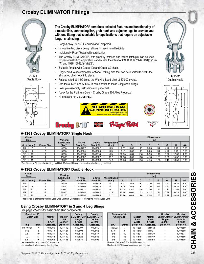
The Crosby ELIMINATOR® combines selected features and functionality of a master link, connecting link, grab hook and adjuster legs to provide you with one fitting that is suitable for applications that require an adjustable length chain sling.• Forged Alloy Steel - Quenched and Tempered. • Innovative two piece design allows for maximum flexibility.• Individually Proof Tested with certification.• The Crosby ELIMINATOR®, with properly installed and locked latch pin, can be used
for personnel lifting applications and meets the intent of OSHA Rule 1926.1431(g)(1)(i)(A) and 1926.1501(g)(4)(iv)(B).
• Suitable for use with Grade 100 and Grade 80 chain.• Engineered to accommodate optional locking pins that can be inserted to “lock” the
shortened chain legs into place.• Fatigue rated at 1-1/2 times the Working Load Limit at 20,000 cycles.• Use the A-1361 and A-1362 in combination to make 3 leg chain slings.• Load pin assembly instructions on page 276.• “Look for the Platinum Color - Crosby Grade 100 Alloy Products.”• All sizes are RFID EQUIPPED.
ChainSize
Frame Size
WorkingLoad Limit
(lbs.)*A-1361
Stock No.L-1361
Stock No.Weight Each
(lbs.)
Dimensions(in.)
(in.) (mm) A B C D E G H AA1/4 7 2 4300 1049797 1049802 3.9 8.20 3.88 .90 3.00 .94 4.40 9.78 3.505/16 8 2 5700 1049804 1049809 3.9 8.18 3.88 .90 3.00 .94 4.40 9.78 3.503/8 10 3 8800 1049813 1049818 6.5 10.05 4.81 1.16 3.50 1.13 5.20 12.06 4.001/2 13 4 15000 1049822 1049827 13.5 12.88 6.00 1.63 4.13 1.31 6.39 15.57 5.005/8 16 5 22600 1049831 1049836 24.1 15.26 6.88 1.96 4.75 1.63 7.41 18.58 6.00
A-1361 Crosby ELIMINATOR® Single Hook
* Proof tested at 2.5 times the Working Load Limit. Minimum Ultimate Load is 4 times the Working Load Limit.
ChainSize
Frame Size
WorkingLoad Limit
(lbs.)*A-1362
Stock No.L-1362
Stock No.Weight Each
(lbs.)
Dimensions(in.)
(in.) (mm) A B C D E G H AA1/4 7 2 8600 1049859 1049913 4.7 8.20 3.88 .90 3.00 .94 4.40 10.10 3.505/16 8 2 11400 1049868 1049922 4.7 8.18 3.88 .90 3.00 .94 4.40 10.10 3.503/8 10 3 17600 1049877 1049931 8.1 10.05 4.81 1.16 3.50 1.13 5.20 12.56 4.001/2 13 4 30000 1049886 1049940 17.3 12.88 6.00 1.63 4.13 1.31 6.39 16.25 5.005/8 16 5 45200 1049895 1049949 31.5 15.26 6.88 1.96 4.75 1.63 7.41 19.33 6.00
A-1362 Crosby ELIMINATOR® Double Hook
* Proof tested at 2 times the Working Load Limit. Minimum Ultimate Load is 4 times the Working Load Limit.
Spectrum 10 Chain Size Master
LinkA-342
Stock No.
MasterLink
A-1342Stock No.
CrosbyELIMINATOR®
SingleA-1361
Stock No.
CrosbyELIMINATOR®
Double A-1362
Stock No.(in.) (mm)1/4 (9/32) 7 1014285 1011412 1049797 1049859
5/16 8 1014319 1011421 1049804 10498683/8 10 1014331 1011430 1049813 10498771/2 13 1014348 1011449 1049822 10498865/8 16 1014365 1011458 1049831 1049895
Spectrum 10 Chain Size Master
LinkA-342
Stock No.
MasterLink
A-1342Stock No.
CrosbyELIMINATOR®
SingleA-1361
Stock No.
CrosbyELIMINATOR®
Double A-1362
Stock No.(in.) (mm)1/4 (9/32) 7 1014285 1011412 – 1049859
5/16 8 1014319 1011421 – 10498683/8 10 1014331 1011430 – 10498771/2 13 1014348 1011449 – 10498865/8 16 1014365 1011458 – 1049895
Use one of either A-342 or A-1342 master link.Use one of each when making three leg sling.
Use one of either A-342 or A-1342 master link.Use two A-1362 fittings when making quad leg sling.
Using Crosby ELIMINATOR® in 3 and 4 Leg SlingsSee page 222-223 for basic chain sling components.
Crosby ELIMINATOR Fittings
On Pages 269-270
SEE APPLICATION AND WARNING INFORMATION
Para Español: www.thecrosbygroup.com
A-1361Single Hook
A-1362Double Hook
Chain Sling Components
Copyright © 2016 The Crosby Group LLC All Rights Reserved
CH
AIN
& A
CC
ES
SO
RIE
S
269
CROSBY ELIMINATOR®
WARNING & APPLICATION INSTRUCTIONS
WARNING• Failure to read, understand, and follow these instructions
may cause death or serious injury.
• Read and understand these instructions before using the Crosby ELIMINATOR®.
• Incorrectly rigging or terminating exerts additional force or loading, which the Crosby ELIMINATOR® is not designed to accommodate.
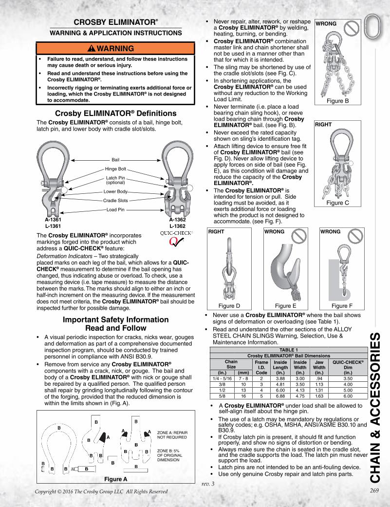
Crosby ELIMINATOR® DefinitionsThe Crosby ELIMINATOR® consists of a bail, hinge bolt, latch pin, and lower body with cradle slot/slots.
The Crosby ELIMINATOR® incorporates markings forged into the product which address a QUIC-CHECK® feature:Deformation Indicators – Two strategically placed marks on each leg of the bail, which allows for a QUIC-CHECK® measurement to determine if the bail opening has changed, thus indicating abuse or overload. To check, use a measuring device (i.e. tape measure) to measure the distance between the marks. The marks should align to either an inch or half-inch increment on the measuring device. If the measurement does not meet criteria, the Crosby ELIMINATOR® bail should be inspected further for possible damage.
Important Safety InformationRead and Follow
• A visual periodic inspection for cracks, nicks wear, gouges and deformation as part of a comprehensive documented inspection program, should be conducted by trained personnel in compliance with ANSI B30.9.
• Remove from service any Crosby ELIMINATOR® components with a crack, nick, or gouge. The bail and body of a Crosby ELIMINATOR® with nick or gouge shall be repaired by a qualified person. The qualified person shall repair by grinding longitudinally following the contour of the forging, provided that the reduced dimension is within the limits shown in (Fig. A).
Figure A
Bail
Hinge Bolt
Latch Pin(optional)
Lower Body
Cradle Slots
Load Pin
A-1361L-1361
A-1362L-1362
ZONE A: REPAIR NOT REQUIRED
ZONE B: 5% OF ORIGINAL DIMENSION
WRONG
Figure B
RIGHT
Figure C
RIGHT
Figure D
WRONG
Figure E
WRONG
Figure F
• Never repair, alter, rework, or reshape a Crosby ELIMINATOR® by welding, heating, burning, or bending.
• Crosby ELIMINATOR® combination master link and chain shortener shall not be used in a manner other than that for which it is intended.
• The sling may be shortened by use of the cradle slot/slots (see Fig. C).
• In shortening applications, the Crosby ELIMINATOR® can be used without any reduction to the Working Load Limit.
• Never terminate (i.e. place a load bearing chain sling hook), or reeve load bearing chain through Crosby ELIMINATOR® bail. (see Fig. B).
• Never exceed the rated capacity shown on sling’s identification tag.
• Attach lifting device to ensure free fit of Crosby ELIMINATOR® bail (see Fig. D). Never allow lifting device to apply forces on side of bail (see Fig. E), as this condition will damage and reduce the capacity of the Crosby ELIMINATOR®.
• The Crosby ELIMINATOR® is intended for tension or pull. Side loading must be avoided, as it exerts additional force or loading which the product is not designed to accommodate. (see Fig. F).
• Never use a Crosby ELIMINATOR® where the bail shows signs of deformation or overloading (see Table 1).
• Read and understand the other sections of the ALLOY STEEL CHAIN SLINGS Warning, Selection, Use & Maintenance Information.
TABLE 1Crosby ELIMINATOR® Bail Dimensions
ChainSize
FrameI.D.
Code
InsideLength
(in.)
InsideWidth(in.)
JawWidth(in.)
QUIC-CHECK®
Dim(in.)(in.) (mm)
1/4 - 5/16 7 - 8 2 3.88 3.00 .94 3.503/8 10 3 4.81 3.50 1.13 4.001/2 13 4 6.00 4.13 1.31 5.005/8 16 5 6.88 4.75 1.63 6.00
• A Crosby ELIMINATOR® under load shall be allowed to self-align itself about the hinge pin.
• The use of a latch may be mandatory by regulations or safety codes; e.g. OSHA, MSHA, ANSI/ASME B30.10 and B30.9.
• If Crosby latch pin is present, it should fit and function properly, and show no signs of distortion or bending.
• Always make sure the chain is seated in the cradle slot, and the cradle supports the load. The latch pin must never support the load.
• Latch pins are not intended to be an anti-fouling device. • Use only genuine Crosby repair and latch pins parts.
rev. 3

Copyright © 2016 The Crosby Group LLC All Rights Reserved270
A-1361 Single Leg Crosby ELIMINATOR®
• The A-1361 single leg Crosby ELIMINATOR® is designed to support a single leg vertical load. The cradle slot may be used to make a loop in the leg (see Fig. G). However, the Working Load Limit is still limited to the single leg values shown in Table 4 (Grade 100) and Table 5 (Grade 80).
• To produce a single basket hitch and achieve the full Working Load Limit, use only one length of chain with both ends terminated into the load pins of two A-1361 single leg Crosby ELIMINATOR® fittings (see Fig. H). Basket may be shortened with cradle slot.
• Never exceed the single leg Working Load Limit shown in Table 4 (Grade 100) and Table 5 (Grade 80) for an individual A-1361 Crosby ELIMINATOR® fitting.
A-1362 Double Leg Crosby ELIMINATOR®
• The A-1362 double leg Crosby ELIMINATOR® is designed to support symmetrically loaded double leg slings at 60, 45, and 30 degree horizontal angles. The cradle slots may be used to make loops in the legs (see Fig. J). However, the Working Load Limit is limited to the double leg values shown in Table 4 (Grade 100) and Table 5 (Grade 80).
• To produce a single basket hitch, and achieve the full Working Load Limit, use only one length of chain with both ends terminated into the load pin (see Fig. K). Basket may be shortened with the cradle slot or slots.
• To produce a double basket hitch and achieve the full Working Load Limit, two A-1362 double leg Crosby ELIMINATOR® fittings must be used, with both being terminated at their load pin (see Fig. L).
• Never exceed the double leg / single basket Working Load Limit on an individual A-1362 Crosby ELIMINATOR® fitting.
RIGHT
Figure H
RIGHT
Figure G
Capacity limited to Single Leg
RIGHT
Figure J
RIGHT
Figure K
Capacity limited to Double Leg
RIGHT
Figure L