ELG4125 Transmission and Distribution Electric …rhabash/ELG4125LN12012.pdf · Transmission and...
47
ELG4125 Transmission and Distribution Electric Systems Electric Power Systems are a technical Wonder! Electricity and its accessibility are the greatest engineering achievements of the twentieth century, ahead of computers and airplanes!
Transcript of ELG4125 Transmission and Distribution Electric …rhabash/ELG4125LN12012.pdf · Transmission and...
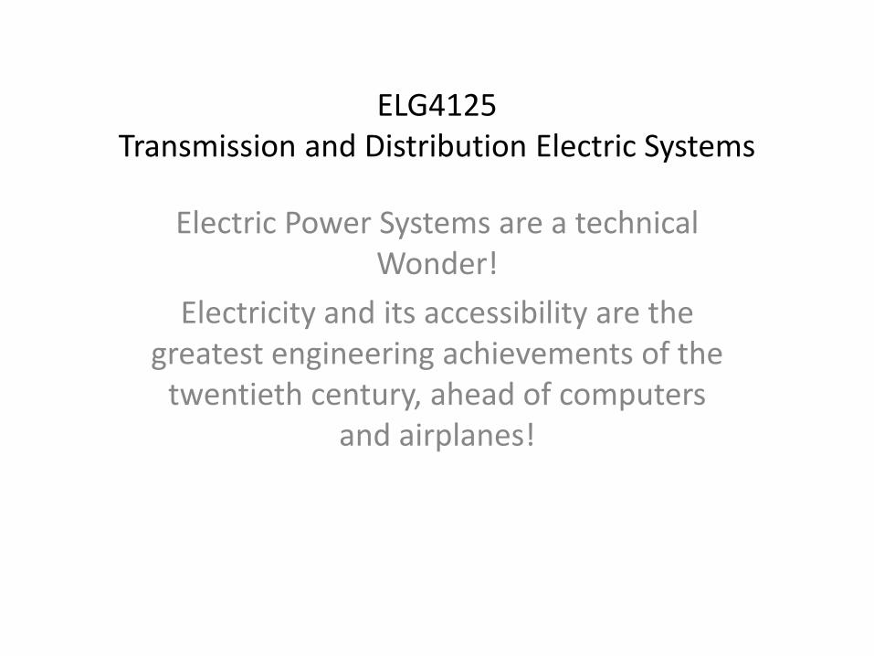
ELG4125 Transmission and Distribution Electric Systems
Electric Power Systems are a technical Wonder!
Electricity and its accessibility are the greatest engineering achievements of the
twentieth century, ahead of computers and airplanes!
2
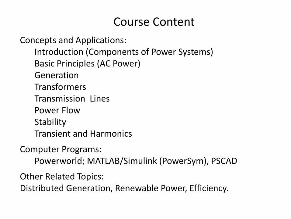
Course Content
Concepts and Applications: Introduction (Components of Power Systems) Basic Principles (AC Power) Generation Transformers Transmission Lines Power Flow Stability Transient and Harmonics
Computer Programs: Powerworld; MATLAB/Simulink (PowerSym), PSCAD
Other Related Topics: Distributed Generation, Renewable Power, Efficiency.
Project Themes You may consider one of the following, but not limited to, themes
3
Small Hydro Power Plant: Feasibility Study for Recovery of Plant Community Power: Feasibility Study of Developing Wind Power Generation Project. Consumers Energy: Control Center in Ottawa: Work on possible projects at the Control Center.
4
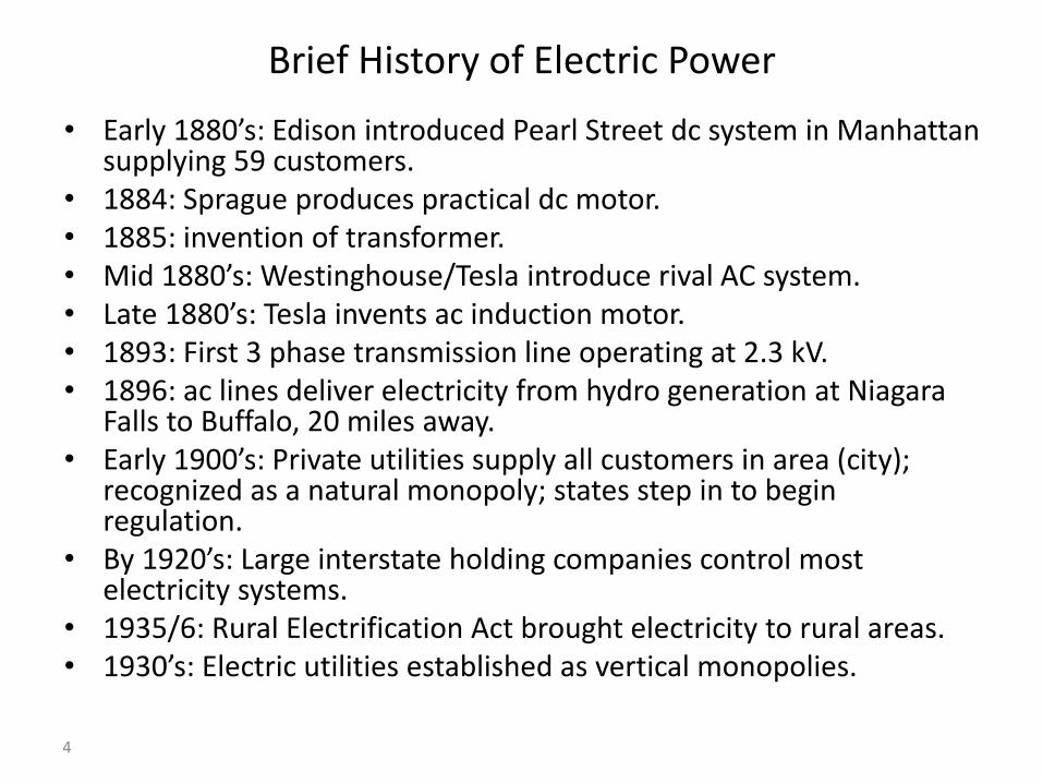
Brief History of Electric Power
• Early 1880’s: Edison introduced Pearl Street dc system in Manhattan supplying 59 customers.
• 1884: Sprague produces practical dc motor. • 1885: invention of transformer. • Mid 1880’s: Westinghouse/Tesla introduce rival AC system. • Late 1880’s: Tesla invents ac induction motor. • 1893: First 3 phase transmission line operating at 2.3 kV. • 1896: ac lines deliver electricity from hydro generation at Niagara
Falls to Buffalo, 20 miles away. • Early 1900’s: Private utilities supply all customers in area (city);
recognized as a natural monopoly; states step in to begin regulation.
• By 1920’s: Large interstate holding companies control most electricity systems.
• 1935/6: Rural Electrification Act brought electricity to rural areas. • 1930’s: Electric utilities established as vertical monopolies.

5
Power System Components : Electrical Components
Light bulb Socket Wire to switch
Switch Wire to circuit box Circuit breaker
Watt-hour-meter Connection to distribution system Distribution transformer
Distribution system Substation Capacitors
Circuit breakers Disconnects Buses
Transformers Sub-transmission system Capacitor banks
Tap changers Current transformers Potential transformers
Protective relaying Reactors Metal-oxide varistors
Transmission system Suspension insulators Lightning arrestors
Generator step-up transformers Generators
Introductory Terms and Concepts
6
Simple Power System
• Every power system has three major components:
– Generation: source of power, ideally with a specified voltage and frequency.
– Load or demand: consumes power; ideally with a constant resistive value.
– Transmission system: transmits power; ideally as a perfect conductor.
• Additional components include:
– Distribution system: local reticulation of power.
– Control equipment: coordinate supply with load.
7
Power
• Power: – Instantaneous rate of consumption of energy, – How hard you work!
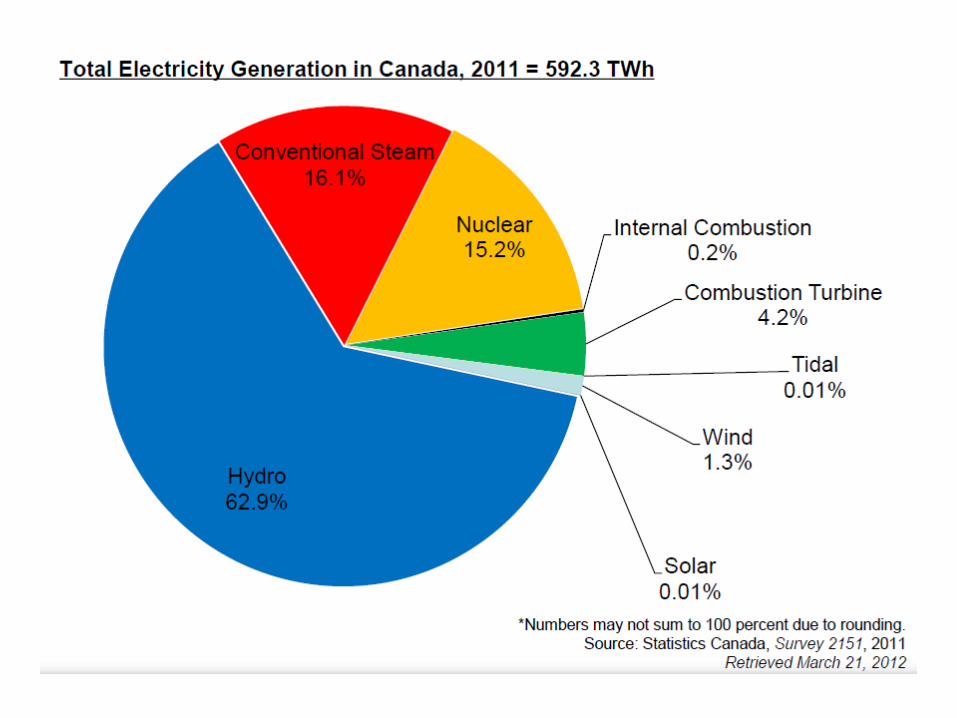
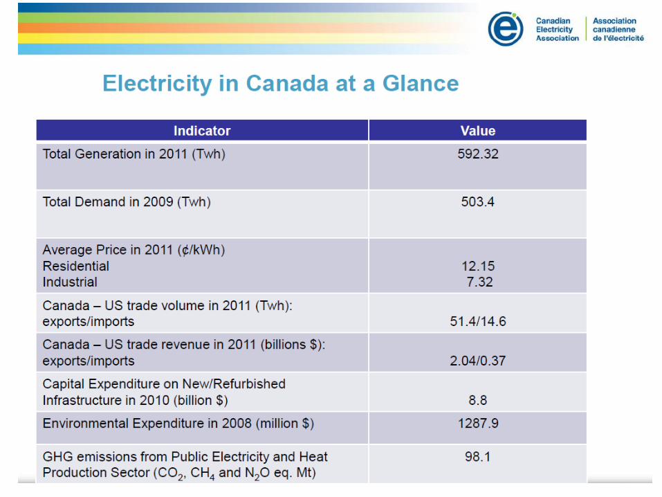
• Power = Voltage x Current for DC • Power Units: Watts = amps times volts (W) kW – 1 x 10³ Watt MW – 1 x 10⁶ Watt GW – 1 x 10⁹ Watt • Installed Canadian generation capacity is about
592 TWh. • Maximum load of Ottawa may be about 2500 MW. • Maximum load of uOttawa campus is about 50 MW.
8
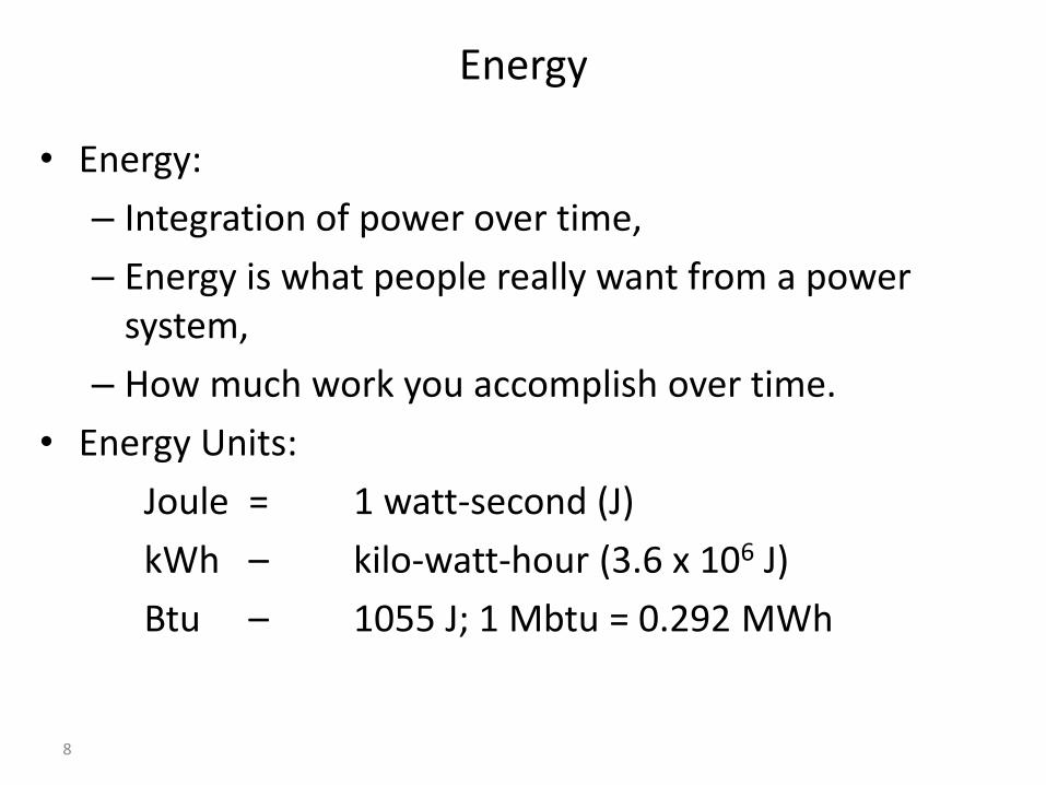
Energy
• Energy:
– Integration of power over time,
– Energy is what people really want from a power system,
– How much work you accomplish over time.
• Energy Units:
Joule = 1 watt-second (J)
kWh – kilo-watt-hour (3.6 x 10⁶ J)
Btu – 1055 J; 1 Mbtu = 0.292 MWh
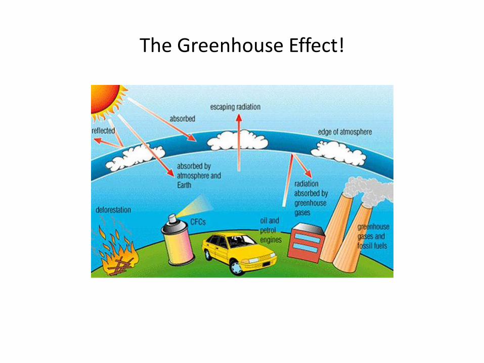
The Greenhouse Effect!
21
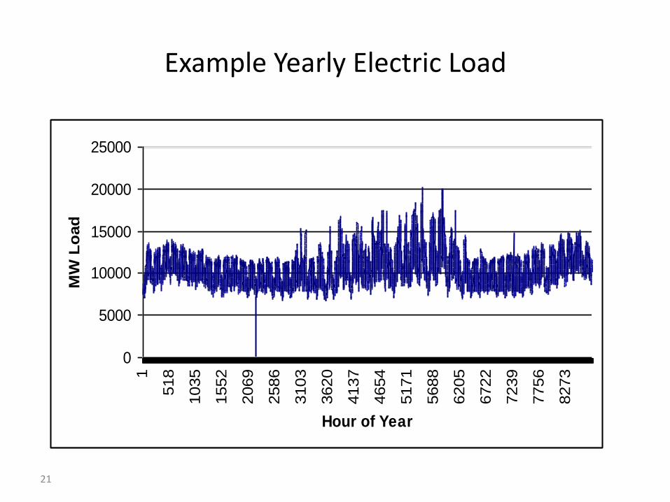
Example Yearly Electric Load
0
5000
10000
15000
20000
250001
518
1035
1552
2069
2586
3103
3620
4137
4654
5171
5688
6205
6722
7239
7756
8273
Hour of Year
MW
Lo
ad
Review of Basic Electric Circuits
• Phasor Representation in Sinusoidal Steady State
• Power, Reactive Power, and Power Factor
• Power Factor Correction
• Three Phase Circuits
• Real and Reactive Power Transfer Between AC Systems
• Apparatus Ratings, Base Values, and Per Unit Quantities
• Energy Efficiency
• Read Example 2.1; Example 2.2; Example 2.3; Example 2.5.
Review of Electromagnetic Concepts
• Ampere’s Law
• Flux Concepts
• Ferromagnetic Materials
• Inductances
• Faraday’s Law
• Leakage and Magnetizing Inductances.
24
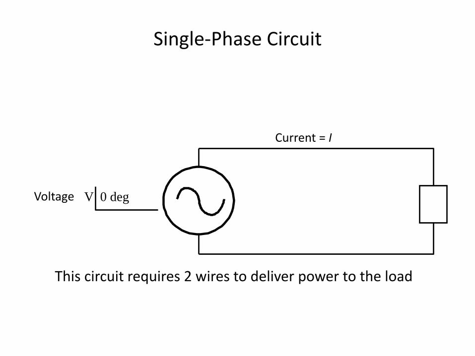
Single-Phase Circuit
Voltage V 0 deg
Current = I
This circuit requires 2 wires to deliver power to the load
25
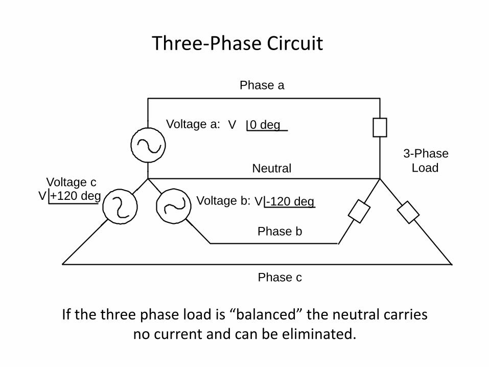
Three-Phase Circuit
If the three phase load is “balanced” the neutral carries no current and can be eliminated.
Voltage a: V 0 deg
Phase a
Voltage c V +120 deg Voltage b: V -120 deg
Phase b
Phase c
Neutral 3-Phase
Load
26
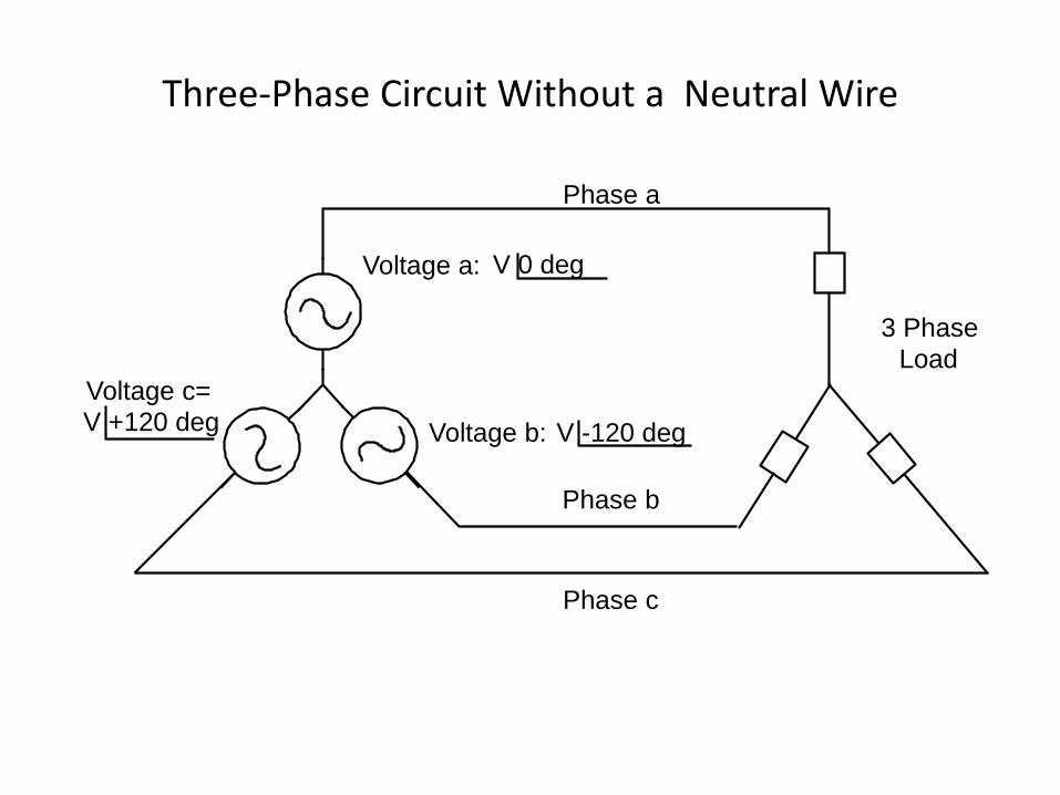
Three-Phase Circuit Without a Neutral Wire
3 Phase Load
Voltage a: V 0 deg
Phase a
Voltage c= V +120 deg Voltage b: V -120 deg
Phase b
Phase c
27
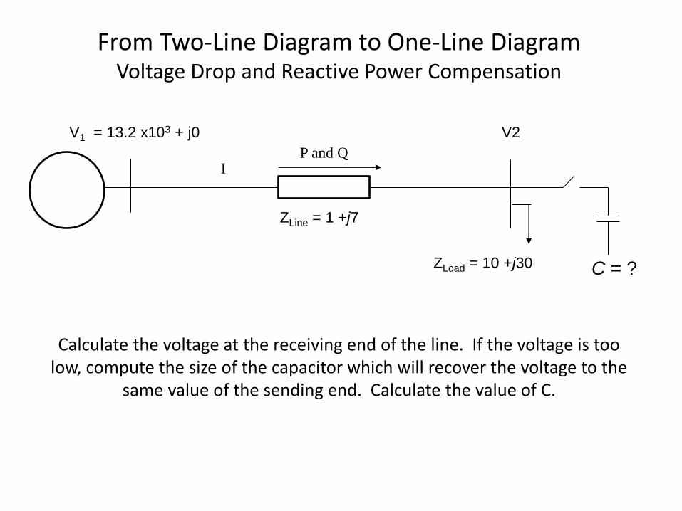
From Two-Line Diagram to One-Line Diagram Voltage Drop and Reactive Power Compensation
V2
ZLine = 1 +j7
V1 = 13.2 x10³ + j0
I P and Q
ZLoad = 10 +j30 C = ?
Calculate the voltage at the receiving end of the line. If the voltage is too low, compute the size of the capacitor which will recover the voltage to the
same value of the sending end. Calculate the value of C.
28
The Per Unit System
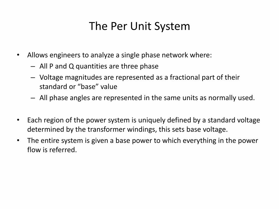
• Allows engineers to analyze a single phase network where:
– All P and Q quantities are three phase
– Voltage magnitudes are represented as a fractional part of their standard or “base” value
– All phase angles are represented in the same units as normally used.
• Each region of the power system is uniquely defined by a standard voltage determined by the transformer windings, this sets base voltage.
• The entire system is given a base power to which everything in the power flow is referred.
29
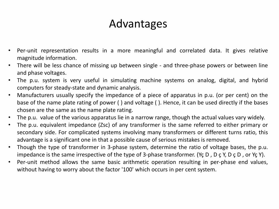
• Per-unit representation results in a more meaningful and correlated data. It gives relative magnitude information.
• There will be less chance of missing up between single - and three-phase powers or between line and phase voltages.
• The p.u. system is very useful in simulating machine systems on analog, digital, and hybrid computers for steady-state and dynamic analysis.
• Manufacturers usually specify the impedance of a piece of apparatus in p.u. (or per cent) on the base of the name plate rating of power ( ) and voltage ( ). Hence, it can be used directly if the bases chosen are the same as the name plate rating.
• The p.u. value of the various apparatus lie in a narrow range, though the actual values vary widely. • The p.u. equivalent impedance (Zsc) of any transformer is the same referred to either primary or
secondary side. For complicated systems involving many transformers or different turns ratio, this advantage is a significant one in that a possible cause of serious mistakes is removed.
• Though the type of transformer in 3-phase system, determine the ratio of voltage bases, the p.u. impedance is the same irrespective of the type of 3-phase transformer. (Yç D , D ç Y, D ç D , or Yç Y).
• Per-unit method allows the same basic arithmetic operation resulting in per-phase end values, without having to worry about the factor '100' which occurs in per cent system.
Advantages
30
Specify the MVA base. Typically this will be related to the rating of a generator, transformer, or transmission line. Just choose the one that will result in the least amount of computation. This base will remain constant throughout the system.
At any location in the circuit, specify a voltage base. This will typically be the nominal voltage for that particular location.
Determine the voltage base for all other areas in the circuit by adjusting by the turns ratio every time a transformer is encountered.
Having specified the voltage and MVA base throughout the system, current and impedance bases may be determined as:
For each value, the per unit quantity is the actual value divided by the base value.
For 3phase circuits, the following relationships must also be included.
Conversion Procedure
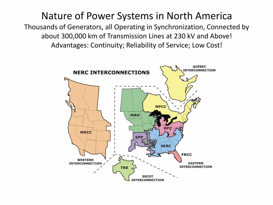
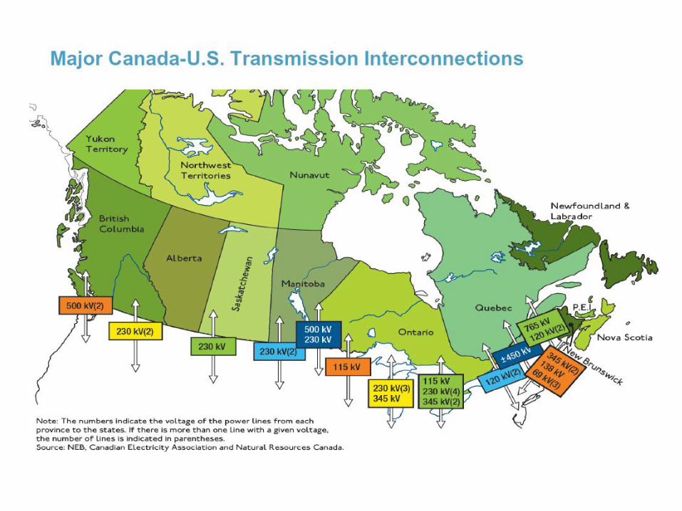
Nature of Power Systems in North America Thousands of Generators, all Operating in Synchronization, Connected by
about 300,000 km of Transmission Lines at 230 kV and Above! Advantages: Continuity; Reliability of Service; Low Cost!
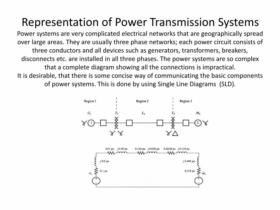
Representation of Power Transmission Systems Power systems are very complicated electrical networks that are geographically spread over large areas. They are usually three phase networks; each power circuit consists of
three conductors and all devices such as generators, transformers, breakers, disconnects etc. are installed in all three phases. The power systems are so complex
that a complete diagram showing all the connections is impractical. It is desirable, that there is some concise way of communicating the basic components
of power systems. This is done by using Single Line Diagrams (SLD).
PowerWorld Simulator http://www.powerworld.com/
Refer to the Course Textbook
• Visit: www.powerworld.com/GloverSarmaOverbye
• Read Section 1.5 of the Textbook!
• Follow Up: Figures 1.6 to 1.8.
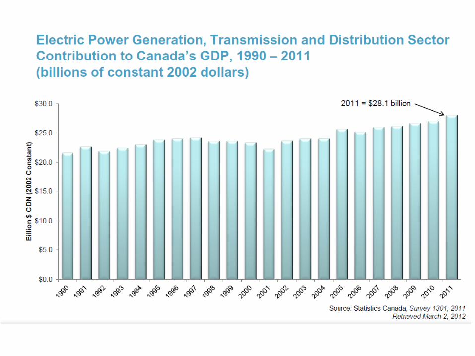
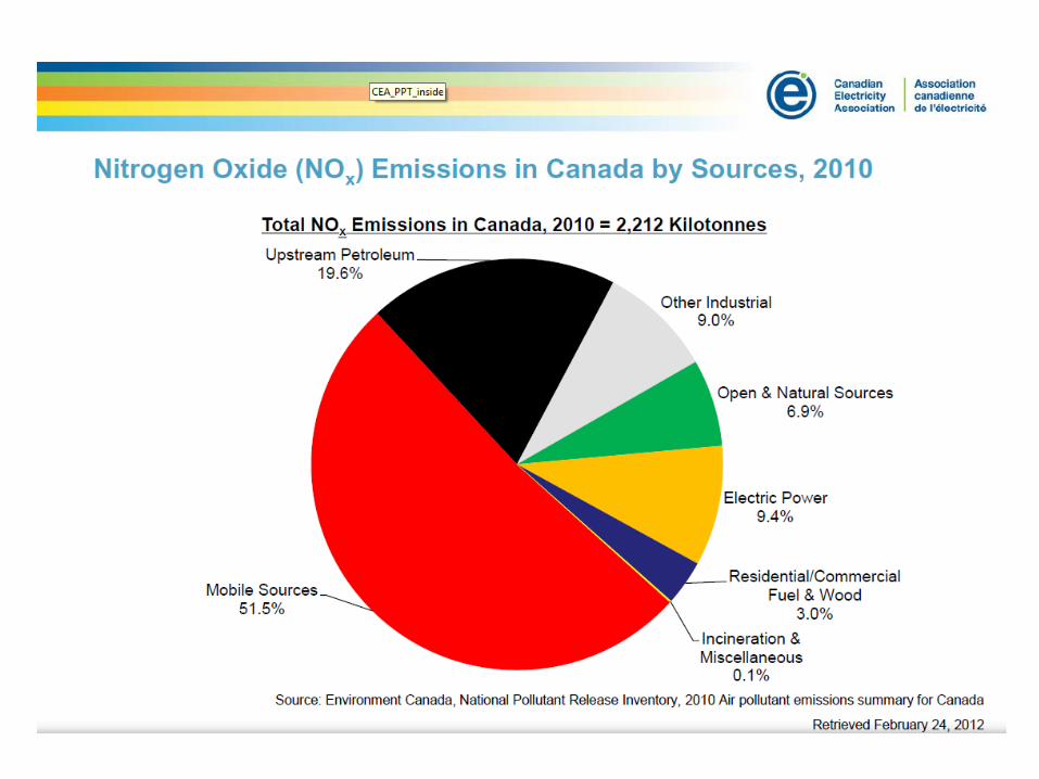
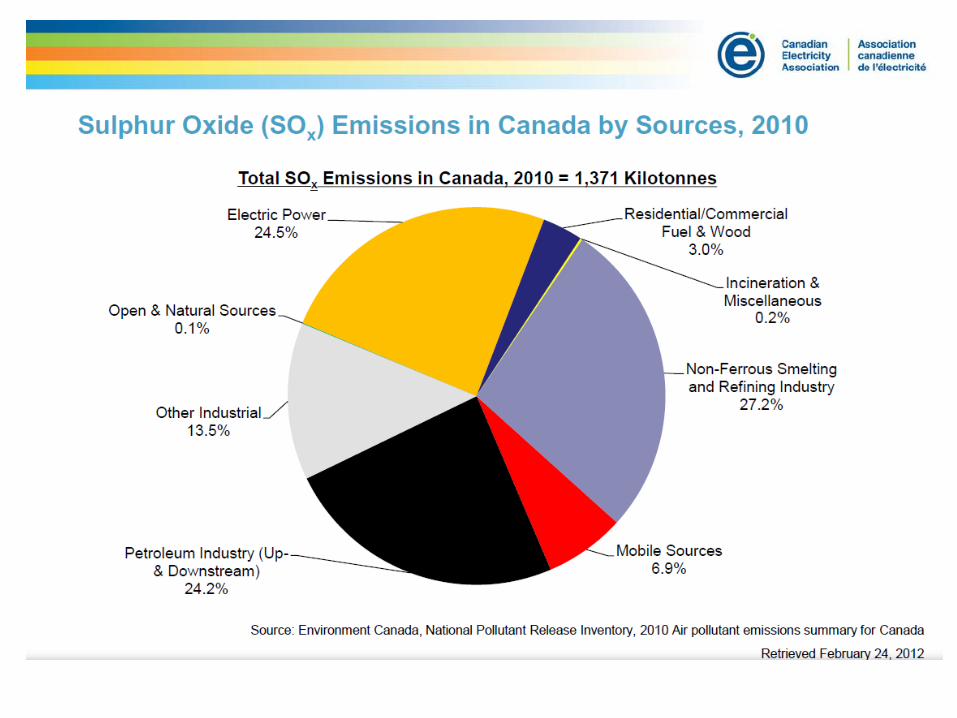
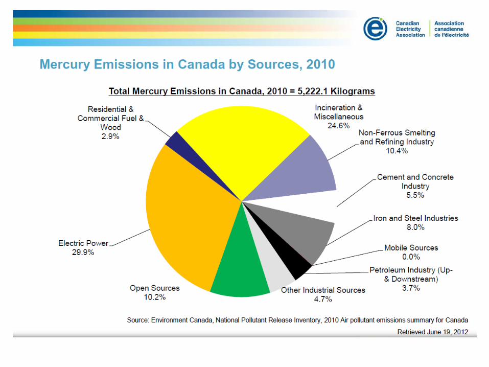
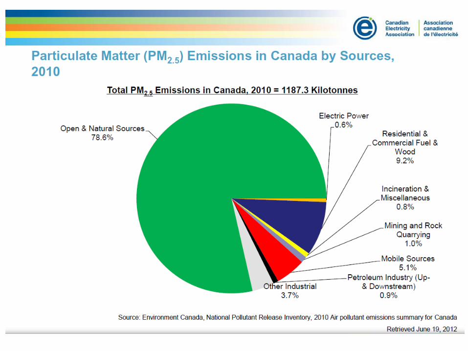
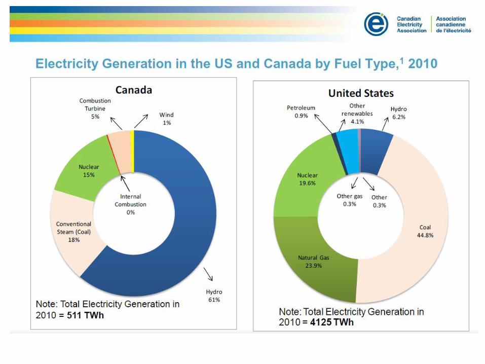
Electric Energy and the Environment
• Choices: – Hydro: Drop in the River; Run-of-River
– Fossil Fuels: Coal; Natural Gas; Oil
– Nuclear: Fusion; Fission Reactors
– Renewable: Wind; Photovoltaic; Fuel cells; Biomass
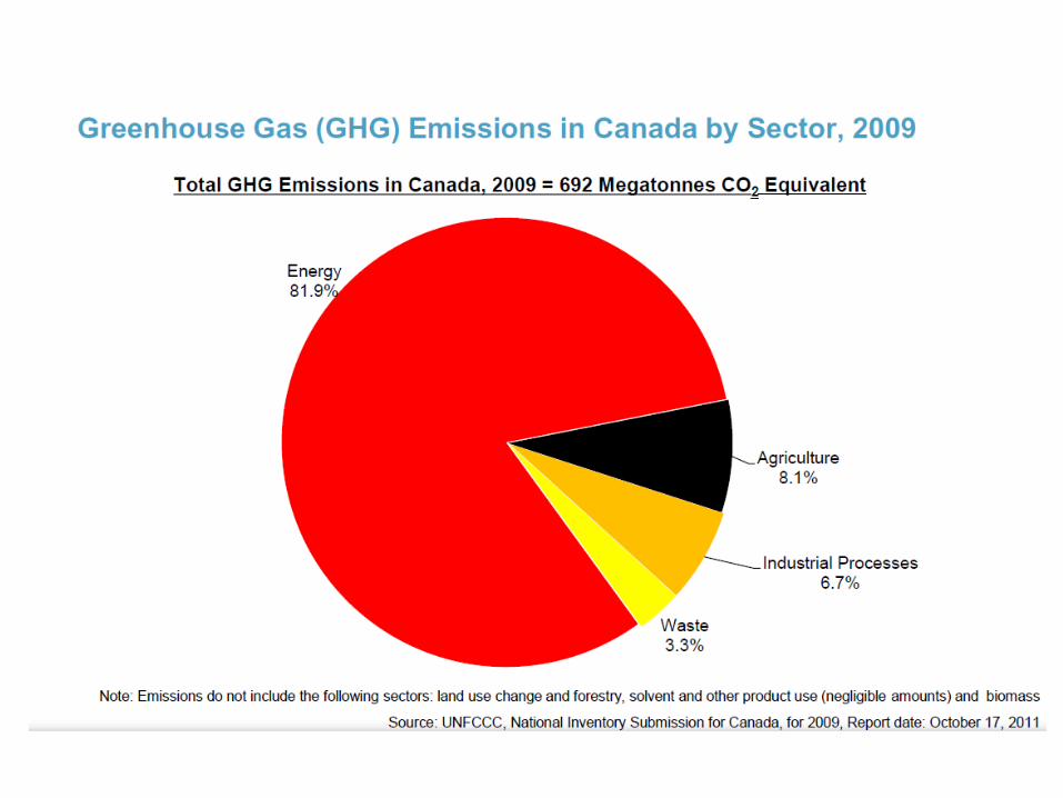
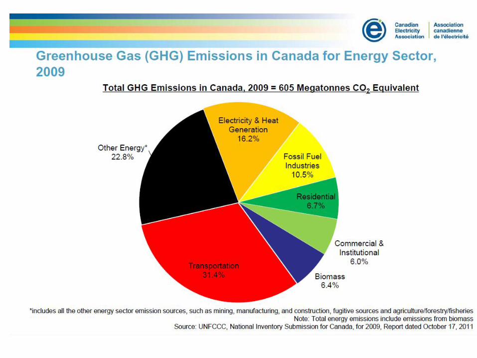
• Consequences: – Greenhouse Gasses
– Sulfur Dioxide
– Nitrogen Oxides
– Mercury
– Thermal Pollution
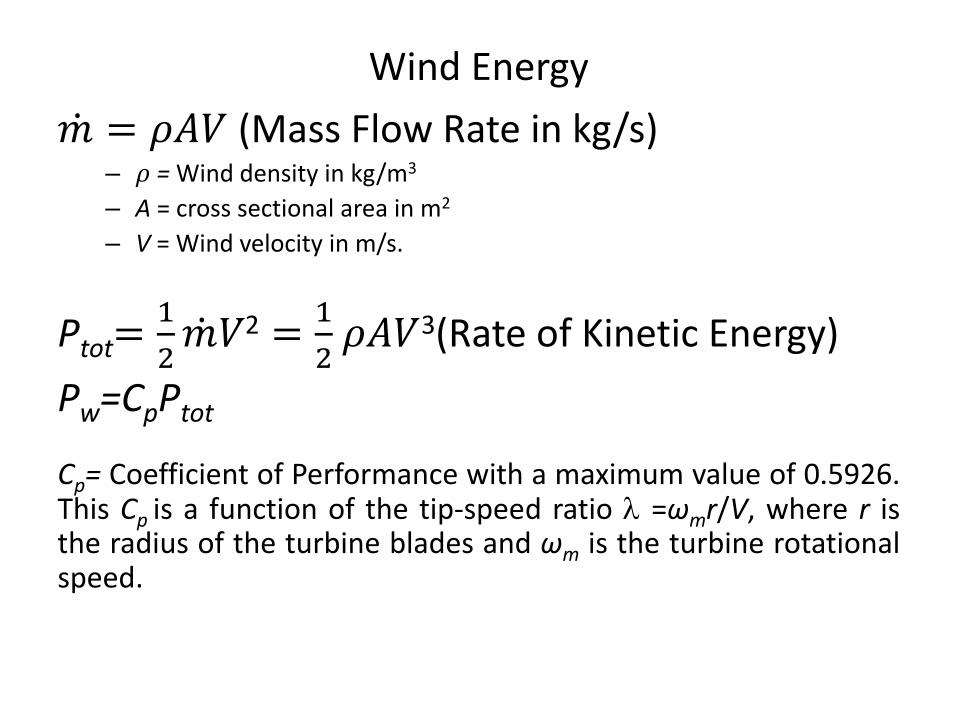
Wind Energy
𝑚 = 𝜌𝐴𝑉 (Mass Flow Rate in kg/s) – 𝜌 = Wind density in kg/m3
– A = cross sectional area in m2
– V = Wind velocity in m/s.
Ptot=1
2𝑚 𝑉2 =
1
2 𝜌𝐴𝑉3(Rate of Kinetic Energy)
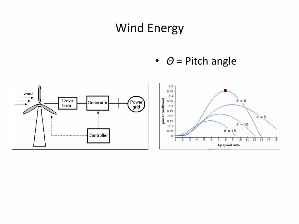
Pw=CpPtot
Cp= Coefficient of Performance with a maximum value of 0.5926. This Cp is a function of the tip-speed ratio =ωmr/V, where r is the radius of the turbine blades and ωm is the turbine rotational speed.
Wind Energy
• Θ = Pitch angle
Photovoltaic Energy
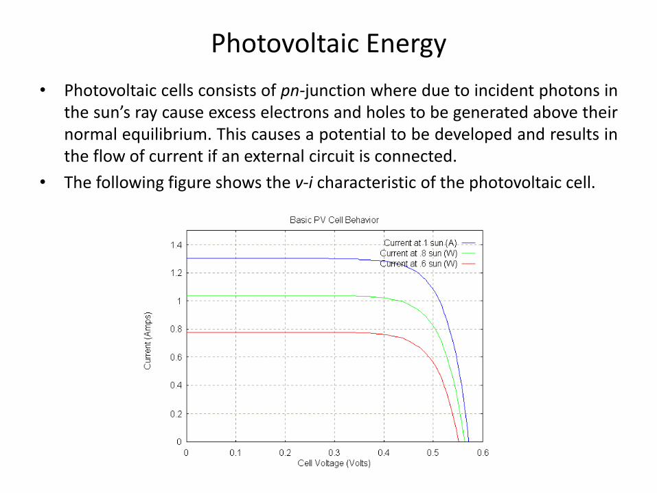
• Photovoltaic cells consists of pn-junction where due to incident photons in the sun’s ray cause excess electrons and holes to be generated above their normal equilibrium. This causes a potential to be developed and results in the flow of current if an external circuit is connected.
• The following figure shows the v-i characteristic of the photovoltaic cell.
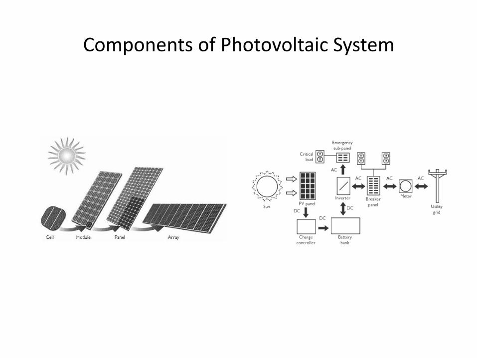
Components of Photovoltaic System

Distributed Generation
• Smaller in Power Rating
• Spurred by Renewable Resources
• Generate Electricity Local to the Load; Minimize the Cost of Transmission and Distribution in addition to Minimizing Losses.
• Utilize the Heat Produced as a Byproduct rather than Throwing it as is Common on Central Generation.
• An Ultimate Advantage would be when the Cost of Wind and Photovoltaic Energy Decrease Significantly.
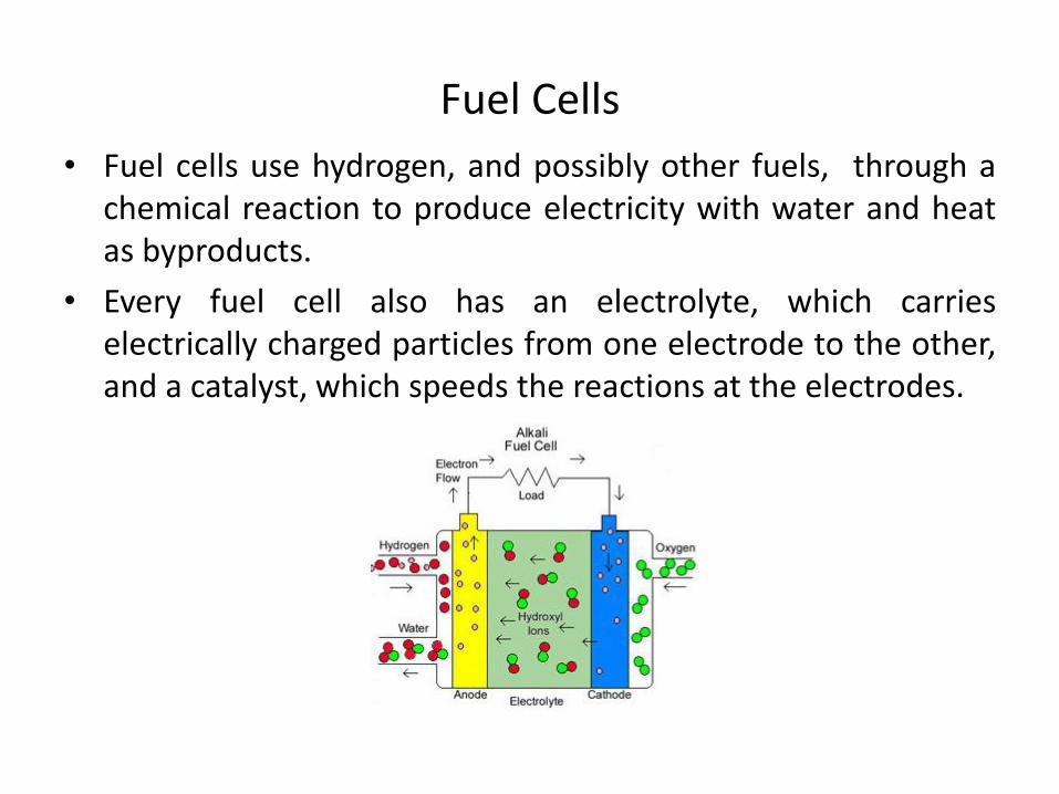
Fuel Cells
• Fuel cells use hydrogen, and possibly other fuels, through a chemical reaction to produce electricity with water and heat as byproducts.
• Every fuel cell also has an electrolyte, which carries electrically charged particles from one electrode to the other, and a catalyst, which speeds the reactions at the electrodes.
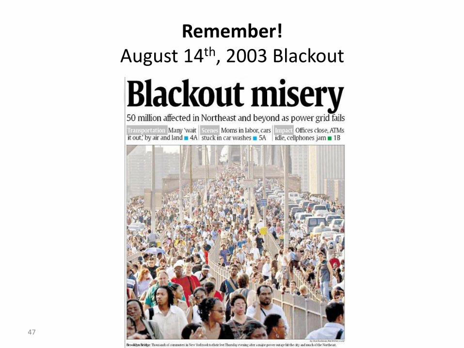
47
Remember! August 14th, 2003 Blackout