Elexon report SSN 20141201 · PDF filethe"intranet.The"control ......
32
Silver Spring Networks CMS Test Evidence Report 1 TEST EVIDENCE REPORT FOR THE CMS SYSTEM Document Reference: SILVERSPRING_CMS_Test_Evidence_Report_V0 Date: 12 November 2014
Transcript of Elexon report SSN 20141201 · PDF filethe"intranet.The"control ......

Silver Spring Networks CMS Test Evidence Report
1
TEST EVIDENCE REPORT FOR THE CMS SYSTEM
Document Reference:
SILVERSPRING_CMS_Test_Evidence_Report_V0
Date: 12 November 2014

Silver Spring Networks CMS Test Evidence Report
2
Test Group Test Requirement Test evidence
Test Group 1
System Configuration The operator of the CMS System should demonstrate the software versioning and operating platforms that will be subject to approval.
The CMS System is named Silver Spring Networks CMS from the company Silver Spring Networks
The following test evidence reports have been created using the version 5.4.0 for the Silver Spring Networks CMS Solution
The operating systems supported by the CMS System are: MS Server 2008, MS Server 2012, MS Vista, MS 7 and MS 8
cf. Appendix: CMS_Test Group1_141114_1_Test 1
Test Group Test Requirement Test evidence
Test Group 2
Security The operator of the CMS System should demonstrate the procedures that provide secure access to data. Operators should only be able to access data that is relevant to them. Secure access procedures should be demonstrated for the following participants:
• HHDC • Suppliers • Customers
Each user accessing the CMS system is identified with a login/password. This login/password pair is linked to a user profile. The rights granted to a user are defined in the CMS platform for each user profile. cf. Appendix: CMS_Test Group2_141114_1_Test 2

Silver Spring Networks CMS Test Evidence Report
3
Test Group Test Requirement Test evidence
Test Group 3
Synchronisation to UTC
The operator of the CMS System should demonstrate that the CMS System is synchronized to UTC, either by connection to internet time servers or a radio clock, and are accurate to within ± 20 seconds per month.
The clock for Silver Spring Networks CMS is using the system clock available on the server. This server can be synchronized with a timeserver on the intranet. The control nodes/photocells synchronize with the access point that is already linked to the online timeserver upon connection.
cf. Appendix:
CMS_Test Group3_141114_1_Test 3
Test Group Test Requirement Test evidence
Test Group 4
Test Group 5
Inventory control information
Equipment control information
The operator of the CMS System should demonstrate the addition, modification and deletion of Inventory Control information required for the key test scenarios, either manually or electronically. The Data subject to testing is:
• Sub-‐Meter ID
cf. Appendix:
CMS_Test Group4_141114_1_Test 4
Silver Spring Networks CMS Test Evidence Report
4
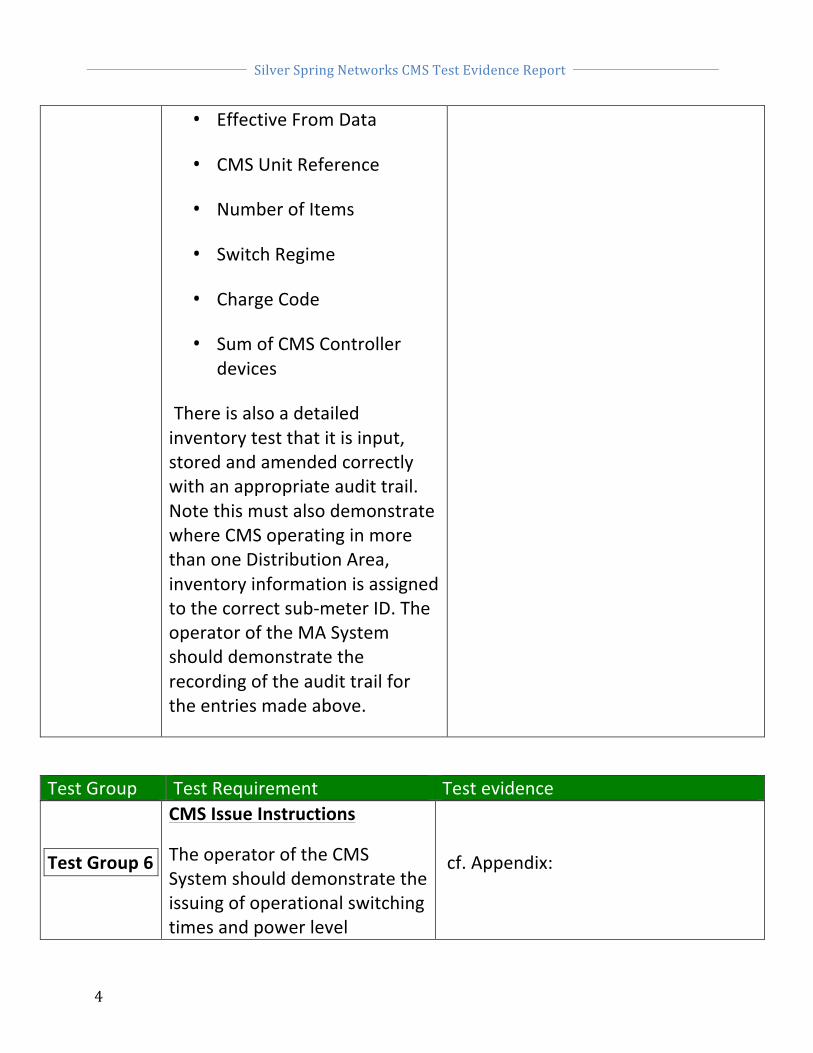
• Effective From Data
• CMS Unit Reference
• Number of Items
• Switch Regime
• Charge Code
• Sum of CMS Controller devices
There is also a detailed inventory test that it is input, stored and amended correctly with an appropriate audit trail. Note this must also demonstrate where CMS operating in more than one Distribution Area, inventory information is assigned to the correct sub-‐meter ID. The operator of the MA System should demonstrate the recording of the audit trail for the entries made above.
Test Group Test Requirement Test evidence
Test Group 6
CMS Issue Instructions
The operator of the CMS System should demonstrate the issuing of operational switching times and power level
cf. Appendix:

Silver Spring Networks CMS Test Evidence Report
5
instructions for CMS Units in the CMS System for the following scenarios:
Test 6.1 Scenario 1 – Switch Regime 999 CMS_Test Group6_141114_1_6.1
Test 6.2 Scenario 2 – Switch Regime 998 CMS_Test Group6_141114_1_6.2
Test 6.3 Scenario 3 – Control Failure (no data for a CMS Unit) CMS_Test Group6_141114_1_6.3
Test 6.4 Scenario 4 – Revised Data after control failure (following day) CMS_Test Group6_141114_1_6.4
Test Group Test Requirement Test evidence
Test Group 7
Record operational switching times and power levels
The operator of the CMS System should demonstrate the recording of operational switching times and power levels for CMS Units in the CMS System for the following scenarios:
cf. Appendix:
Test 7.1 Scenario 1 – Switch Regime 999 CMS_Test Group7_141114_1_7.1
Test 7.2 Scenario 2 – Switch Regime 998 CMS_Test Group7_141114_1_7.2
Test 7.3 Scenario 3 – Control Failure (no data for a CMS Unit) CMS_Test Group7_141114_1_7.3

Silver Spring Networks CMS Test Evidence Report
6
Test 7.4 Scenario 4 – Revised Data after control failure (following day) CMS_Test Group7_141114_1_7.4
Test 7.5 Audit Trail
Test Group Test Requirement Test evidence
Test Group 8
Generate Operational Event Log -‐ normal processing and control failure
The operator of the CMS System should demonstrate:
The sending of a daily operational event logs (CMS and MA Separate Systems) or if applicable transferring of data (CMS and MA integrated Systems) of the operational switching times and power levels for specified CMS Units to the MA in the specified format for the following scenarios:
cf. Appendix:
Test 8.1 Scenario 1 – Switch Regime 999 CMS_Test Group8_141114_1_8.1
Test 8.2 Scenario 2 – Switch Regime 999 CMS_Test Group8_141114_1_8.2
Test 8.3 Scenario 3 – Control Failure CMS_Test Group8_141114_1_8.3
Test 8.4 Scenario 4 – Revised Data after CMS_Test Group8_141114_1_8.4

Silver Spring Networks CMS Test Evidence Report
7
control failure (following day)
Test 8.5 Available daily (Separate CMS and MA System) CMS_Test Group8_141114_1_8.5
Test 8.7 Audit Trail
Test Group Test Requirement Test evidence
Test Group 9
Volume and Performance
The operator of the CMS System should provide tests evidence of volume and performance tests completed by the applicant as part of their system testing, to the accredited test agent so that compliance with operational timescales can be accessed.
Cf. Appendix: CMS_TestGroup9_141114_1_9
Test Group Test Requirement Test evidence
Test Group 10
Operational Event Log – File format
The operator of the CMS System should demonstrate that the operational event logs are in the specified format as per BSCP520 Section 4.5.2.3 (c).
cf. Appendix:
CMS_Test Group10_141114_1_10

Silver Spring Networks CMS Test Evidence Report
8
APPENDIX CMS_Test Group1_141114_1_1 standing for:
Test System: Central Management System
Test Group: 1
Run Date: 141114
Run Number: 1
Test Ref: 1.1 and 1.2
Ø In the rest of the document, only the abbreviated formulation will be used.
CMS software version
The CMS System is named Silver Spring Networks CMS from the company SILVER SPRING NETWORKS and the current release used for the current tests is Version 5.4.0. The screenshot below displays the ‘about’ window of the Silver Spring Networks CMS Web portal.
The version control for Silver Spring Networks CMS is defined as follows: first digit indicates the major release version number, second digit indicates the minor release version number and third and last digit indicates patch number. Additional information can be found on the “Build” item, starting with year/month/day of the release.

Silver Spring Networks CMS Test Evidence Report
9
CMS_Test Group2_141114_1_Test 2
System Security
The user enters his unique login/password to enter the CMS System platform. Each ‘User’ is linked to a ‘Profile’ with specific grants to visualize, edit and update the data.
Silver Spring Networks CMS Test Evidence Report
10
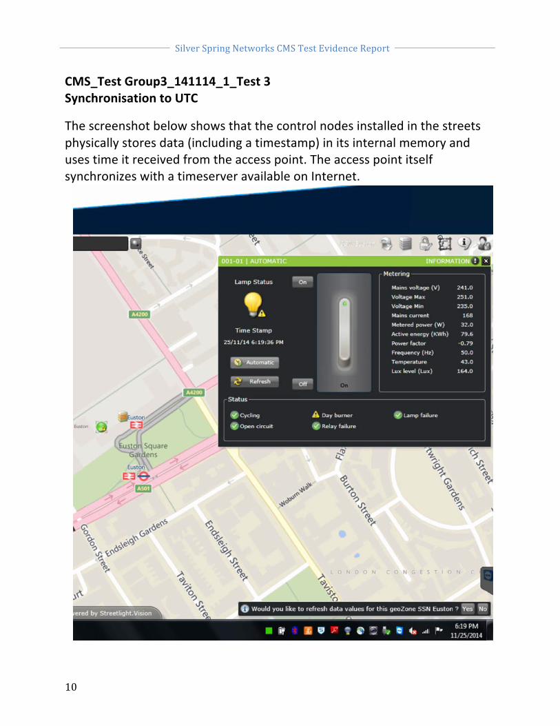
CMS_Test Group3_141114_1_Test 3 Synchronisation to UTC
The screenshot below shows that the control nodes installed in the streets physically stores data (including a timestamp) in its internal memory and uses time it received from the access point. The access point itself synchronizes with a timeserver available on Internet.

Silver Spring Networks CMS Test Evidence Report
11
CMS_Test Group4_141114_1_Test 4
Detailed Inventory information
The Inventory Platform that is used to generate the Control file for CMS-‐controlled equipment is not the Silver Spring Networks CMS; it is a geographic information system: GIS (e.g the Insight Solution from the company Symology).
The inventory information requested in the Silver Spring Networks CMS to generate the Event Log files are added, modified, and deleted through a CSV file import/export.
The diagram below displays the interaction between the entities:

Silver Spring Networks CMS Test Evidence Report
12
The screenshots below demonstrate the process to Add, delete, and modify the inventory information requested in the Silver Spring Networks CMS.

Silver Spring Networks CMS Test Evidence Report
13
Creating a new Streetlight:
Viewing / editing existing control node information:

Silver Spring Networks CMS Test Evidence Report
14
The following screenshot displays to mechanism to assign the dimming profile (field Dimming group in the Equipment Inventory app) for each CMS unit (or each group of CMS units).
Then the Scheduling Manager app is used:

Silver Spring Networks CMS Test Evidence Report
15
For the test report, the Dimming group ‘default’ assigned to the test lamp 001-‐01 shown above follows the scenario 1 (998 dimming) on weekdays and scenario 2 (999 continuous burning) on weekends (with automatic switch on/off based on an astroclock) as shown below:
Screenshot Test 4.2 -‐ Audit Trail
The Silver Spring Networks CMS CMS platform stores a log (with information for the user, action and timestamp) for every action initiated by a user. The administrator can access this data anytime. The data remains stored for one year by default.

Silver Spring Networks CMS Test Evidence Report
16
CMS_Test Group6_141114_1_6.1
CMS Issue Instructions -‐ Scenario 1 – switch regime 999
Event Time On/Off % Full Power (Circuit Watts) Duration
1 At Dusk (automatic) 100% 30 min
2 After 30 min 75 % For 90 min
3 After 120 min 50 % For 60 min
4 After 180 min 75% For 120 min
5 After 300 min 100% Till Dawn
6 At Dawn (automatic) 0% Off
Based on the scenario 1 – Switch Regime 999 as displayed above, Silver Spring Networks CMS is configured to control the CMS units (streetlights) with the following dimming profile:

Silver Spring Networks CMS Test Evidence Report
17
Based on the dimming profile configured in Silver Spring Networks CMS, the graph below display the commands set to the CMS units (streetlights). The reports focus here on a single CMS unit.
Statements on communication protocols:
Silver Spring Networks CMS is using the IPV6 protocol (with a large number of backhaul networking choice, such as 3G, fiber, DSL, GPRS…) for the communication between the server platform and controller nodes on the field. The communication between the access point and the CMS units is managed using the RF mesh networking technology (IEEE 802.15.4g standard).

Silver Spring Networks CMS Test Evidence Report
18
CMS_Test Group6_141114_1_6.2
CMS Issue Instructions -‐ Scenario 2 – Switch Regime 998
Event Time On/Off % Full Power (Circuit Watts) Duration
1 Continuous burning 100% For 60 min
Based on the scenario 2 – Switch Regime 998 as displayed above, the CMS system has been configured to control the CMS units (streetlights) with the following schedule:

Silver Spring Networks CMS Test Evidence Report
19
Based on the schedule configured in the CMS System, the graph and the table bellow display the commands set to the CMS units. The reports focus here on a single CMS unit.
Silver Spring Networks CMS Test Evidence Report
20
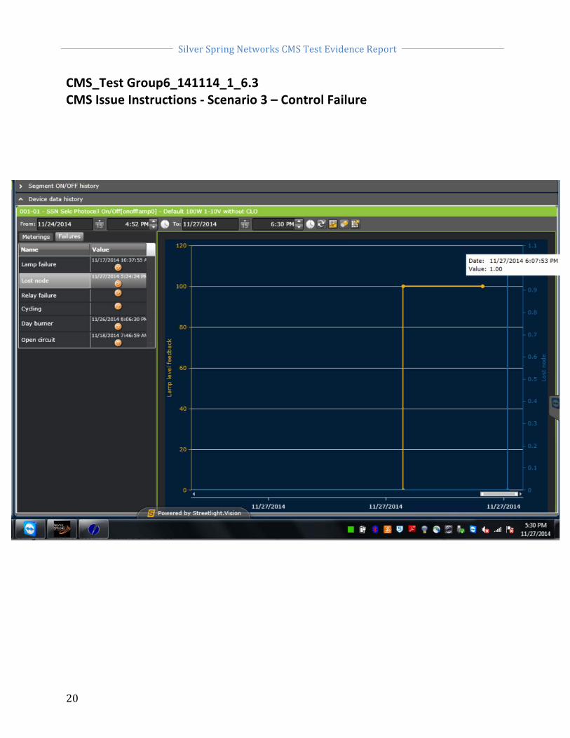
CMS_Test Group6_141114_1_6.3 CMS Issue Instructions -‐ Scenario 3 – Control Failure

Silver Spring Networks CMS Test Evidence Report
21
CMS_Test Group6_141114_1_6.4 CMS Issue Instructions – Scenario 4 – Revised Data after control failure (following day)
Below is displayed the Lost node (communication failure) for both scenarios with data that has been recovered after the failures

Silver Spring Networks CMS Test Evidence Report
22
CMS_Test Group7_141114_1_7.1 Record operational switching times and power levels -‐ Scenario 1 – Switch Regime 999
Following the commands set by the SLV CMS system to the CMS units, the table below displays the feedback information from the CMS unit with operational switching times and power levels for that CMS unit. Those records are stored in the CMS database and were displayed on appendix graph 6.1.
Lamp level feedback 11/03/14 16:32 100.0 Lamp level feedback 11/03/14 17:02 75.0 Lamp level feedback 11/03/14 18:32 50.0 Lamp level feedback 11/03/14 19:32 75.0 Lamp level feedback 11/03/14 21:32 100.0 Lamp level feedback 11/04/14 07:00 0.0 Lamp level feedback 11/04/14 16:30 100.0 Lamp level feedback 11/04/14 17:00 75.0 Lamp level feedback 11/04/14 18:30 50.0 Lamp level feedback 11/04/14 19:30 75.0 Lamp level feedback 11/04/14 21:30 100.0 Lamp level feedback 11/05/14 07:02 0.0 Lamp level feedback 11/05/14 16:28 100.0 Lamp level feedback 11/05/14 16:58 75.0 Lamp level feedback 11/05/14 18:28 50.0 Lamp level feedback 11/05/14 19:28 75.0 Lamp level feedback 11/05/14 21:28 100.0 Lamp level feedback 11/06/14 07:03 0.0 Lamp level feedback 11/06/14 16:26 100.0 Lamp level feedback 11/06/14 16:56 75.0

Silver Spring Networks CMS Test Evidence Report
23
CMS_Test Group7_141114_1_7.2 Record operational switching times and power levels -‐ Scenario 2 – Switch Regime 998
Following the commands set by the SLV CMS system to the CMS units, the table below displays the feedback information from the CMS unit with operational switching times and power levels for that CMS unit. Those records are stored in the CMS database and were displayed on appendix graph 6.2.
Lamp level feedback 11/06/14 18:52 100.0 Lamp level feedback 11/10/14 12:53 0.0
Silver Spring Networks CMS Test Evidence Report
24
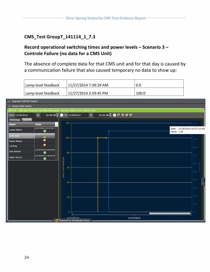
CMS_Test Group7_141114_1_7.3
Record operational switching times and power levels – Scenario 3 – Controle Failure (no data for a CMS Unit)
The absence of complete data for that CMS unit and for that day is caused by a communication failure that also caused temporary no data to show up:
Lamp level feedback 11/27/2014 7:39:29 AM 0.0
Lamp level feedback 11/27/2014 3:59:45 PM 100.0

Silver Spring Networks CMS Test Evidence Report
25

Silver Spring Networks CMS Test Evidence Report
26
CMS_Test Group7_141114_1_7.4 Record operational switching times and power levels – Scenario 4 -‐ Revised Data after control failure (following day)
In this scenario, the full feedback for that CMS Unit is received but one day later (data from then November 27th-‐28th) that expected (simulating a communication issue for example in the communication between the Node controller and SSN CMS supervisor). The feedback records for that CMS Unit is not in line with the commands set (in CMS_TestGroup6_141114_1_6.3) because of the temporary communication failure.
Lamp level feedback 11/27/2014 7:39:29 AM 0.0 Lamp level feedback 11/27/2014 3:59:45 PM 100.0 Lamp level feedback 11/27/2014 4:29:45 PM 75.0 Lamp level feedback 11/27/2014 5:37:07 PM 100.0 Lamp level feedback 11/27/2014 5:59:45 PM 50.0 Lamp level feedback 11/27/2014 6:59:45 PM 75.0 Lamp level feedback 11/27/2014 8:59:45 PM 100.0 Lamp level feedback 11/28/2014 7:40:59 AM 0.0 Lamp level feedback 11/28/2014 11:42:56 AM 0.0

Silver Spring Networks CMS Test Evidence Report
27
CMS_Test Group8_141114_1_8.1
Generate Operational Event Log -‐ Scenario 1 – Switch Regime 999
Silver Spring Networks CMS computes and sends automatically, on a daily basis (everyday at 9AM in this example), the operational event logs to an FTP server. The event logs file is computed based on the recorded operational switching times and power levels stored in the CMS database (feedback information from the CMS Units) as well as the eventual failures information (-‐> information flag).
The screenshot bellow displays the parameters for the CMS System to generate on a daily basis the operational event log and export it on a FTP server. The generated operational event log file is then used by the MA System.
The following event logs file displays the operational switching times and power levels for a specific CMS unit.

Silver Spring Networks CMS Test Evidence Report
28
ssn eus20141103001.log Hssn eus20141103001 001-‐01______140418000.00 001-‐01______163205100.00 001-‐01______170205075.00 001-‐01______183205050.00 001-‐01______193205075.00 001-‐01______213205100.00 T0000008 ssn eus20141104001.log Hssn eus20141104001 001-‐01______070026000.00 001-‐01______163020100.00 001-‐01______170020075.00 001-‐01______183020050.00 001-‐01______193020075.00 001-‐01______213020100.00 T0000008 ssn eus20141105001.log Hssn eus20141105001 001-‐01______070212000.00 001-‐01______162838100.00 001-‐01______165838075.00 001-‐01______182838050.00 001-‐01______192838075.00 001-‐01______212838100.00 T0000008

Silver Spring Networks CMS Test Evidence Report
29
CMS_Test Group8_141114_1_8.2 Generate Operational Event Log -‐ Scenario 2 – Switch Regime 998
The CMS system computes and sends automatically on a daily basis the operational event logs to a designated FTP server and folder. The event logs file is computed based on the feedback data for the CMS units (switching time, power level, and status) stored in the Silver Spring Networks CMS database. The extract from the following event logs file displays the operational switching times and power levels for a specific CMS unit.
ssn eus20141101001.log Hssn eus20141101001 001-‐01______230000100.00 T0000003 CMS_Test Group8_141114_1_8.3
Generate Operational Event Log – Scenario 3 – Control Failure
• For the communication failure mentioned in 6.3 and 7.3, the log report produced before the communication failure is resolved is incomplete, as displayed below:
ssn eus20141127001.log Hssn eus20141127001 001-‐01______073929000.00 001-‐01______155945100.00 T0000004
• Another example is if a lamp failure has been notified (temporary failure during the night) for that CMS. Therefore, a record at 15:55 (time when the lamp failure is notified) appears in the Operational Event Log bellow with an Information Flag=’D’. The % of full power mentioned for that record=000.00 as the system knows for sure that the lamp for that CMS Unit is OFF.

Silver Spring Networks CMS Test Evidence Report
30
The flag ‘D’ disappears in the next record at 16:44 when a new valid feedback is received then for the CMS Unit (% of full power =75.00 and the no more lamp failure).
ssn eus20141114001.log Hssn eus20141114001
001-‐01______071806000.00 001-‐01______155513000.00D 001-‐01______164437075.00 001-‐01______181436050.00 001-‐01______191436075.00 T0000008
Below are listed and detailed the possible values for the information flag in an operational event log.
Flag value Detail
Flag=’ ‘ Default flag (space character) for normal records in the operational event logs
Flag=’D’
This flag is set when a failure is reported by the CMS Unit notifying that the lamp is not burning (at a time it should). At the time this failure information is notified in the CMS System, a records is created in the operational with a % of Full power=000.00 + the flag=’D’
Silver Spring Networks CMS Test Evidence Report
31
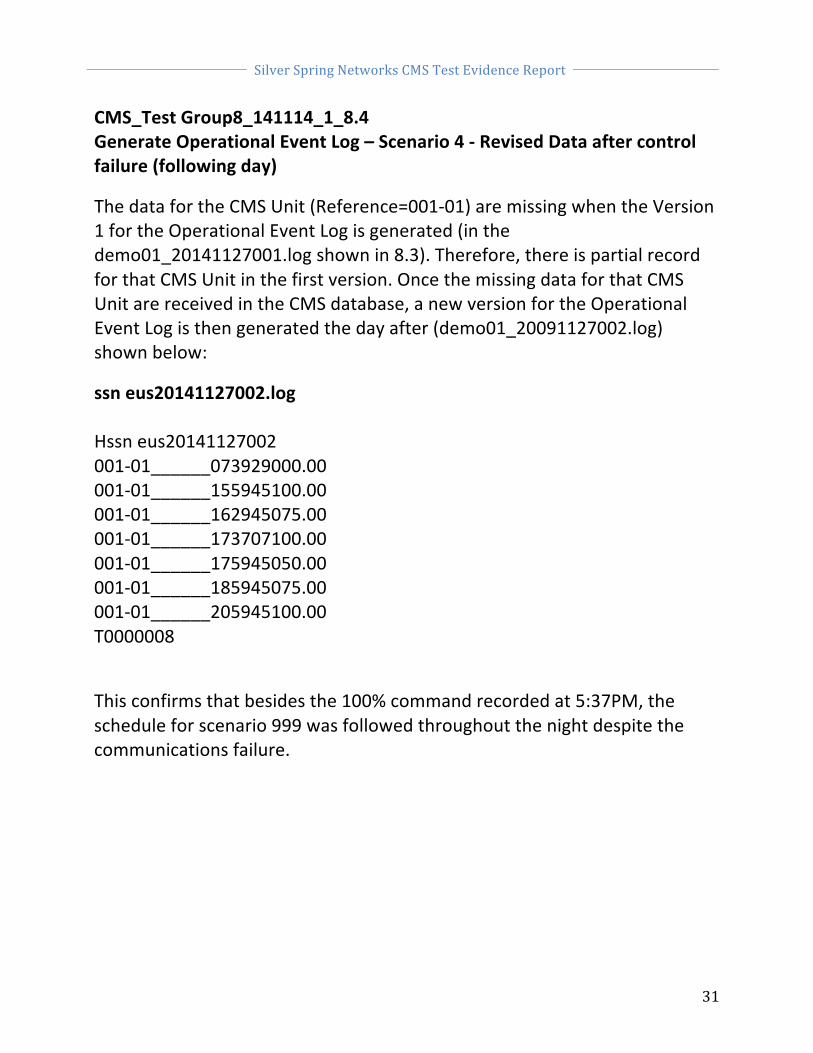
CMS_Test Group8_141114_1_8.4 Generate Operational Event Log – Scenario 4 -‐ Revised Data after control failure (following day)
The data for the CMS Unit (Reference=001-‐01) are missing when the Version 1 for the Operational Event Log is generated (in the demo01_20141127001.log shown in 8.3). Therefore, there is partial record for that CMS Unit in the first version. Once the missing data for that CMS Unit are received in the CMS database, a new version for the Operational Event Log is then generated the day after (demo01_20091127002.log) shown below:
ssn eus20141127002.log Hssn eus20141127002 001-‐01______073929000.00 001-‐01______155945100.00 001-‐01______162945075.00 001-‐01______173707100.00 001-‐01______175945050.00 001-‐01______185945075.00 001-‐01______205945100.00 T0000008
This confirms that besides the 100% command recorded at 5:37PM, the schedule for scenario 999 was followed throughout the night despite the communications failure.

Silver Spring Networks CMS Test Evidence Report
32
CMS_Test Group8_141114_1_8.5 Generate Operational Event Log -‐ Available daily
see the test CMS_Test Group8_141114_1_8.1.
CMS_Test Group9_141114_1_9
Compliance with operational timescales
Several databases including thousands of CMS units have been tested in Silver Spring Networks CMS. Those databases have been populated with an average of seven records (% of full power + status) per CMS unit and per day. ) The spread sheet bellow details the time measured for Silver Spring Networks CMS System to generate, in average, the daily event log file. The time mentioned includes the FTP transfer to upload the Operational Event log once generated (available then for the MA System).
Number of CMS units Volume (number of records) Time to generate the event log
1 000 7 000 1s
5 000 35 000
50s
10 000 70 000 2mn
50 000 350 000
8mn
100 000 700 000 16mn
CMS_Test Group10_141114_1_10
Operational Event Log – File format
See the test operational event logs displayed for the section CMS_Test Group8_141114_1_8.4.


![USTA TrafficAnalysisBriefing V7 0 20150530 FINAL[1] · PDF file1."Executive"Summary" ... In2014thethreemajorGulfcarriers" –"Emirates,"Qatar"Airways"and"Etihad" Airways"–"carried"some"4.3"million"passengers"intoandout"of"the](https://static.fdocuments.in/doc/165x107/5aa125967f8b9a46238b5bf2/usta-trafficanalysisbriefing-v7-0-20150530-final1-in2014thethreemajorgulfcarriers.jpg)