Elevator Valve EV 100 - · PDF file3 BLAIN HYDRAULICS GmbH • Pfaffenstrasse 1 •...
15
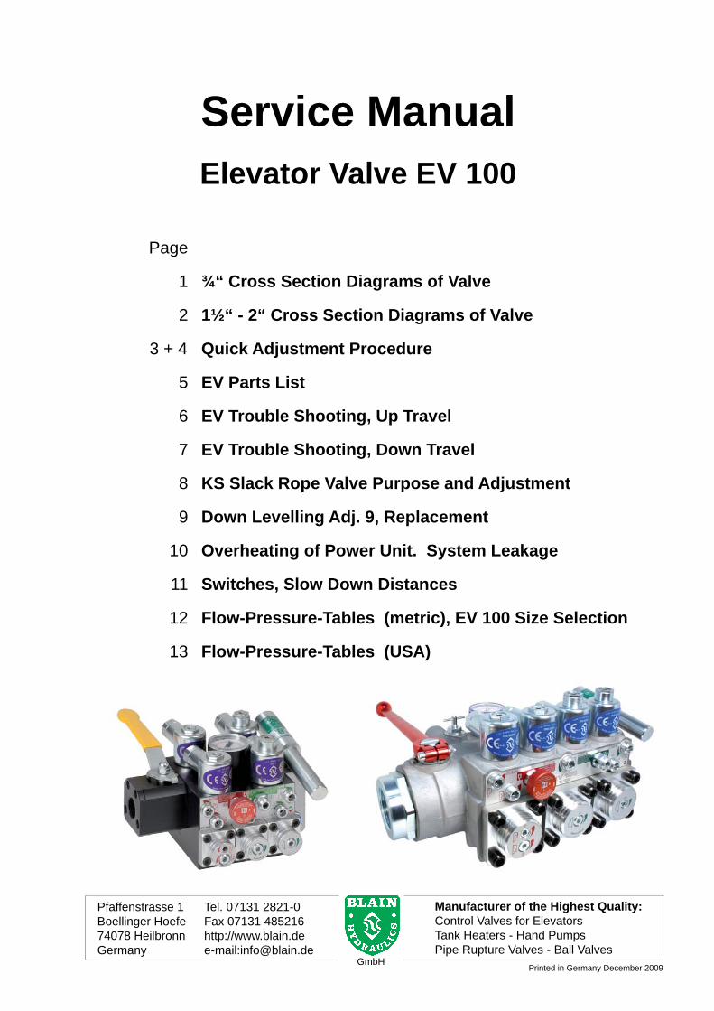
Page 1 ¾“ Cross Section Diagrams of Valve 2 1½“ - 2“ Cross Section Diagrams of Valve 3 + 4 Quick Adjustment Procedure 5 EV Parts List 6 EV Trouble Shooting, Up Travel 7 EV Trouble Shooting, Down Travel 8 KS Slack Rope Valve Purpose and Adjustment 9 Down Levelling Adj. 9, Replacement 10 Overheating of Power Unit. System Leakage 11 Switches, Slow Down Distances 12 Flow-Pressure-Tables (metric), EV 100 Size Selection 13 Flow-Pressure-Tables (USA) Service Manual Elevator Valve EV 100 Pfaffenstrasse 1 Tel. 07131 2821-0 Boellinger Hoefe Fax 07131 485216 74078 Heilbronn http://www.blain.de Germany e-mail:[email protected] Manufacturer of the Highest Quality: Control Valves for Elevators Tank Heaters - Hand Pumps Pipe Rupture Valves - Ball Valves GmbH Printed in Germany December 2009
-
Upload
nguyenhuong -
Category
Documents
-
view
223 -
download
0
Transcript of Elevator Valve EV 100 - · PDF file3 BLAIN HYDRAULICS GmbH • Pfaffenstrasse 1 •...
1BLAIN HYDRAULICS GmbH • Pfaffenstrasse 1 • D-74078 Heilbronn • Tel. +49 7131 28 21-0 • Fax +49 7131 485216 • www.blain.de • [email protected]
EV 100 Service Manual
EN ISO 9001
Page
1 ¾“ Cross Section Diagrams of Valve
2 1½“ - 2“ Cross Section Diagrams of Valve
3 + 4 Quick Adjustment Procedure
5 EV Parts List
6 EV Trouble Shooting, Up Travel
7 EV Trouble Shooting, Down Travel
8 KS Slack Rope Valve Purpose and Adjustment
9 Down Levelling Adj. 9, Replacement
10 Overheating of Power Unit. System Leakage
11 Switches, Slow Down Distances
12 Flow-Pressure-Tables (metric), EV 100 Size Selection
13 Flow-Pressure-Tables (USA)
Service ManualElevator Valve EV 100
Pfaffenstrasse 1 Tel. 07131 2821-0Boellinger Hoefe Fax 07131 48521674078 Heilbronn http://www.blain.deGermany e-mail:[email protected]
Manufacturer of the Highest Quality:Control Valves for ElevatorsTank Heaters - Hand PumpsPipe Rupture Valves - Ball Valves
GmbHPrinted in Germany December 2009
2BLAIN HYDRAULICS GmbH • Pfaffenstrasse 1 • D-74078 Heilbronn • Tel. +49 7131 28 21-0 • Fax +49 7131 485216 • www.blain.de • [email protected]
EV 100 Service Manual
EN ISO 9001
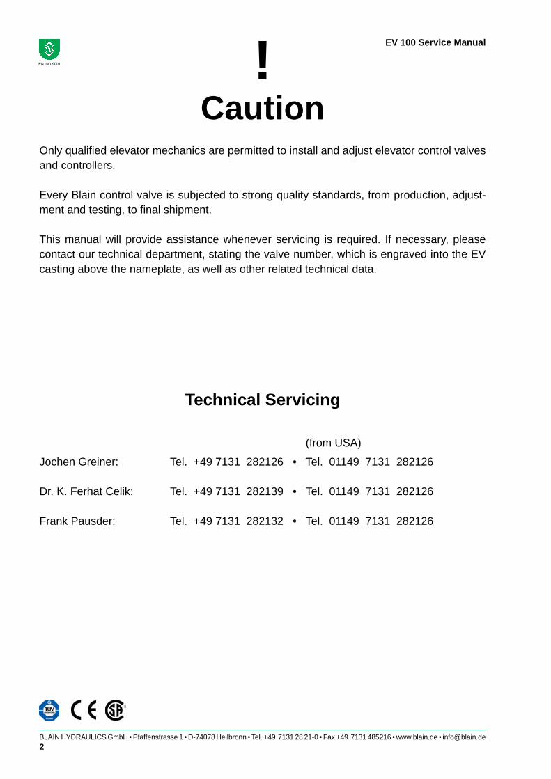
Technical Servicing
Jochen Greiner: Tel. +49 7131 282126 • Tel. 01149 7131 282126
Dr. K. Ferhat Celik: Tel. +49 7131 282139 • Tel. 01149 7131 282126
Frank Pausder: Tel. +49 7131 282132 • Tel. 01149 7131 282126
!Caution
Only qualifi ed elevator mechanics are permitted to install and adjust elevator control valves and controllers.
Every Blain control valve is subjected to strong quality standards, from production, adjust-ment and testing, to fi nal shipment.
This manual will provide assistance whenever servicing is required. If necessary, please contact our technical department, stating the valve number, which is engraved into the EV casting above the nameplate, as well as other related technical data.
(from USA)
3BLAIN HYDRAULICS GmbH • Pfaffenstrasse 1 • D-74078 Heilbronn • Tel. +49 7131 28 21-0 • Fax +49 7131 485216 • www.blain.de • [email protected]
EV 100 Service Manual
EN ISO 9001
EV 100 Service Manual
SteuerelementeA Magnetventil (Halt oben)B Magnetventil (Abbremsen auf)C Magnetventil (Abbremsen unten)D Magnetventil (Halt unten)H NotablassventilS ÜberdruckventilU UmlaufkolbenV RückschlagventilW Schleichfahrtventil (auf)X SenkkolbenY Schleichfahrtventil (ab)
Einstellungen AUF1 Umlaufeinstellung2 Anfahrdrossel3 Abbremsdrossel4 Schleichfahrteinstellung5 Haltedrossel
Einstellungen AB6 Anfahrtdrossel7 Senkfahrteinstellung8 Abbremsdrossel9 Schleichfahrteinstellung
DruckPumpeUmlaufkolben Schleichfahrt (Auf)TankZylinderSenkkolbenSchleichfahrt (Ab)
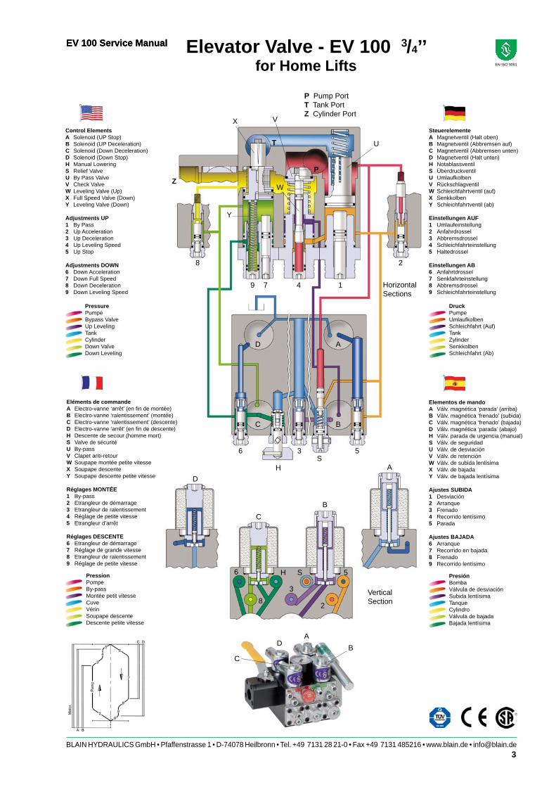
Elevator Valve - EV 100 3/4’’for Home Lifts
7
W
U
Y
X
1
2
P
8
9 4
V
T
Z
6 3
HS
5
A
BC
D
5
2
S
3
H
8
6
A
BC
D
Elementos de mandoA Válv. magnética ‘parada’ (arriba)B Válv. magnética ‘frenado’ (subida)C Válv. magnética ‘frenado’ (bajada)D Válv. magnética ‘parada’ (abajo)H Válv. parada de urgencia (manual)S Válv. de seguridad U Válv. de desviaciónV Válv. de retenciónW Válv. de subida lentísimaX Válv. de bajada Y Válv. de bajada lentísima
Ajustes SUBIDA1 Desviación2 Arranque3 Frenado4 Recorrido lentísimo5 Parada
Ajustes BAJADA6 Arranque 7 Recorrido en bajada8 Frenado 9 Recorrido lentísimo
PresiónBombaVálvula de desviaciónSubida lentísimaTanqueCylindroVálvula de bajadaBajada lentísima
VerticalSection
HorizontalSections
P Pump PortT Tank PortZ Cylinder Port
Control ElementsA Solenoid (UP Stop)B Solenoid (UP Deceleration)C Solenoid (Down Deceleration)D Solenoid (Down Stop)H Manual LoweringS Relief ValveU By Pass ValveV Check ValveW Leveling Valve (Up)X Full Speed Valve (Down)Y Leveling Valve (Down)
Adjustments UP1 By Pass2 Up Acceleration3 Up Deceleration4 Up Leveling Speed5 Up Stop
Adjustments DOWN6 Down Acceleration7 Down Full Speed8 Down Deceleration9 Down Leveling Speed
Eléments de commandeA Electro-vanne ‘arrêt’ (en fi n de montée)B Electro-vanne ‘ralentissement’ (montée)C Electro-vanne ‘ralentissement’ (descente)D Electro-vanne ‘arrêt’ (en fi n de descente)H Descente de secour (homme mort)S Valve de sécurité U By-passV Clapet anti-retourW Soupape montée petite vitesseX Soupape descente Y Soupape descente petite vitesse
Réglages MONTÉE1 By-pass2 Etrangleur de démarrage3 Etrangleur de ralentissement4 Réglage de petite vitesse5 Etrangleur d’arrêt
Réglages DESCENTE6 Etrangleur de démarrage7 Réglage de grande vitesse8 Etrangleur de ralentissement 9 Réglage de petite vitesse
PressionPompeBy-passMontée petit vitesseCuveVérinSoupape descenteDescente petite vitesse
PressurePumpeBypass ValveUp LevelingTankCylinderDown ValveDown Leveling
C
DA
B
4BLAIN HYDRAULICS GmbH • Pfaffenstrasse 1 • D-74078 Heilbronn • Tel. +49 7131 28 21-0 • Fax +49 7131 485216 • www.blain.de • [email protected]
EV 100 Service Manual
EN ISO 9001
7
W
U
Y
X
1
2
P
8
9 4
V
T
Z
6 3
HS
5
ABCD
52S3
H86
ABCD
SteuerelementeA Magnetventil (Halt oben)B Magnetventil (Abbremsen auf)C Magnetventil (Abbremsen unten)D Magnetventil (Halt unten)H NotablassventilS ÜberdruckventilU UmlaufkolbenV RückschlagventilW Schleichfahrtventil (auf)X SenkkolbenY Schleichfahrtventil (ab)
Einstellungen AUF1 Umlaufeinstellung2 Anfahrdrossel3 Abbremsdrossel4 Schleichfahrteinstellung5 Haltedrossel
Einstellungen AB6 Anfahrtdrossel7 Senkfahrteinstellung8 Abbremsdrossel9 Schleichfahrteinstellung
DruckPumpeUmlaufkolben Schleichfahrt (Auf)TankZylinderSenkkolbenSchleichfahrt (Ab)
PressionPompeBy-passMontée petit vitesseCuveVérinSoupape descenteDescente petite vitesse
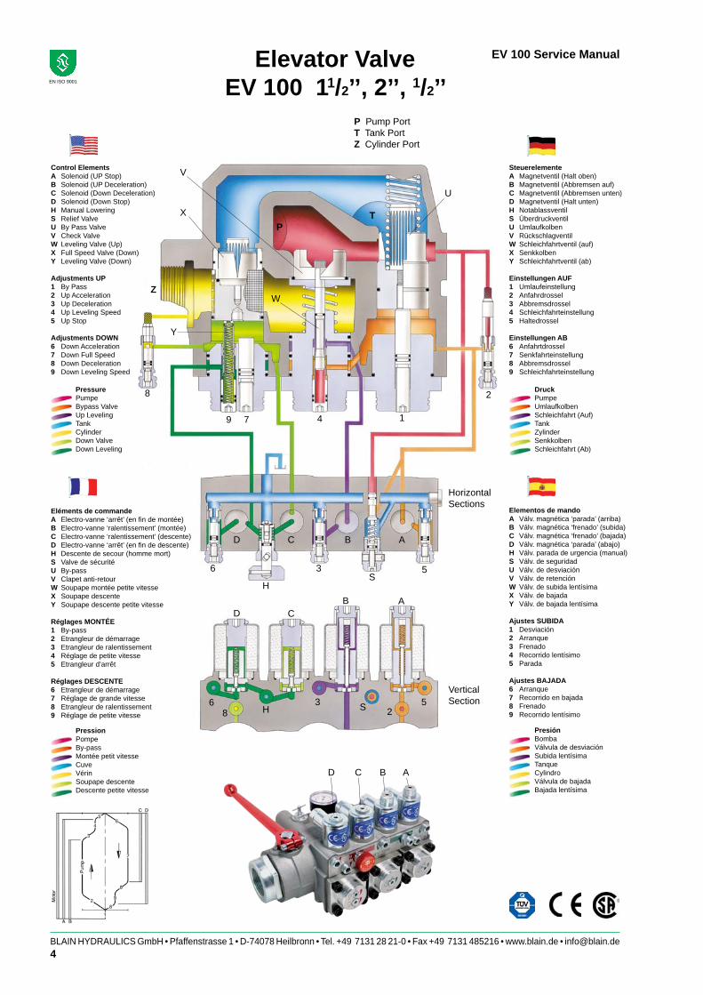
Elevator ValveEV 100 11/2’’, 2’’, 1/2’’
Control ElementsA Solenoid (UP Stop)B Solenoid (UP Deceleration)C Solenoid (Down Deceleration)D Solenoid (Down Stop)H Manual LoweringS Relief ValveU By Pass ValveV Check ValveW Leveling Valve (Up)X Full Speed Valve (Down)Y Leveling Valve (Down)
Adjustments UP1 By Pass2 Up Acceleration3 Up Deceleration4 Up Leveling Speed5 Up Stop
Adjustments DOWN6 Down Acceleration7 Down Full Speed8 Down Deceleration9 Down Leveling Speed
PressurePumpeBypass ValveUp LevelingTankCylinderDown ValveDown Leveling
Eléments de commandeA Electro-vanne ‘arrêt’ (en fi n de montée)B Electro-vanne ‘ralentissement’ (montée)C Electro-vanne ‘ralentissement’ (descente)D Electro-vanne ‘arrêt’ (en fi n de descente)H Descente de secour (homme mort)S Valve de sécurité U By-passV Clapet anti-retourW Soupape montée petite vitesseX Soupape descente Y Soupape descente petite vitesse
Réglages MONTÉE1 By-pass2 Etrangleur de démarrage3 Etrangleur de ralentissement4 Réglage de petite vitesse5 Etrangleur d’arrêt
Réglages DESCENTE6 Etrangleur de démarrage7 Réglage de grande vitesse8 Etrangleur de ralentissement 9 Réglage de petite vitesse
PresiónBombaVálvula de desviaciónSubida lentísimaTanqueCylindroVálvula de bajadaBajada lentísima
Elementos de mandoA Válv. magnética ‘parada’ (arriba)B Válv. magnética ‘frenado’ (subida)C Válv. magnética ‘frenado’ (bajada)D Válv. magnética ‘parada’ (abajo)H Válv. parada de urgencia (manual)S Válv. de seguridad U Válv. de desviaciónV Válv. de retenciónW Válv. de subida lentísimaX Válv. de bajada Y Válv. de bajada lentísima
Ajustes SUBIDA1 Desviación2 Arranque3 Frenado4 Recorrido lentísimo5 Parada
Ajustes BAJADA6 Arranque 7 Recorrido en bajada8 Frenado 9 Recorrido lentísimo
HorizontalSections
P Pump PortT Tank PortZ Cylinder Port
VerticalSection
D C B A

5BLAIN HYDRAULICS GmbH • Pfaffenstrasse 1 • D-74078 Heilbronn • Tel. +49 7131 28 21-0 • Fax +49 7131 485216 • www.blain.de • [email protected]
EV 100 Service Manual
EN ISO 9001
Quick adjustmentprocedure
Solenoid CoilsDuring adjustment of the EV 100 valve, instead of making a full fl oor to fl oor travel to check operation, much time can be saved by removing the securing nuts of the coil and switching to deceleration or to acceleration by lifting or replacing the appropriate coil by hand, allowing several adjustment corrections during one car travel between fl oors.
Caution: Once removed from the solenoid tube, the energised coil will begin to overheat after about 20 secs. If necessary, to slow the rate of heating, place an 8 or 10 mm socket key or similar steel rod as core thru the coil.Do not lay an energised coil to one side, otherwise it may overheat unnoticed.If the coil becomes too hot to hold, it must be replaced, back over the solenoid tube and any further adjustment carried out with the elevator making normal fl oor to fl oor runs.
Car not visible from MachineroomIf the car cannot be seen during adjustment of the valve, the acceleration and deceleration times can be heard from the change of the turbulent noise within the valve as the speed of the car changes. With no load in the car, the duration of the speed changes should be about 2,5 seconds. This applies to adjustments 2, 3, 6 and 8.
Up Travel (empty car)
1. Pilot Pressure SettingDisconnect coil A. Energise Motor (pump).If the car does not move, turn No. 1 ‘in’ until the car begins to move, turn No. 1 ‘out’ until the car stops, then back out again 1/2 turn. The car remains standing still.DO NOT UP-LEVEL WITH THIS ADJUSTMENT! Between full and empty car, levelling speed differences would be extreme.
2. Up AccelerationReconnect coil A. Start Motor and energise coil A and B (normal ‘up’ call).Observe the up acceleration. If it is too quick, turn No. 2 ‘in’ ½ turn. If it is too long, turn No. 2 ‘out’ ½ turn. Repeat until acceleration is satisfactory. Acceleration time should be about 2,5 secs.
4. Up LevellingDisconnect coil B. Energise Motor and coil A (normal ‘up-level’ call).With adjustment No. 4 level with the face of the fl ange the car will up level. If the levell1ing speed is too fast, turn No. 4 ‘in’ until the speed is as required. If the speed is too slow, turn No. 4 ‘out’. Recommended speed 6 cm/sec.
Z1Z1
68
7
9 4
1
3
2
5
S
D C A BD C AB
1
2
5
S
9 4 3
68
7
PRE-SETTINGS EV 100 ¾“ EV 100 1½“ - EV 100 2½“
Adjustment No. 1 level with fl ange face 5 mm Socket key Adjustment No. 2 all the way ‘in’ then 1,5 turns ‘out’ then 2 turns ‘out’ 3 mm Socket key Adjustment No. 4 level with fl ange face 5 mm Socket key Adjustment No. 3 all the way ‘in’ then 1,5 turns ‘out’ then 2,5 turns ‘out’ 3 mm Socket key Adjustment No. 5 all the way ‘in’ then 1,5 turns ‘out’ then 2,5 turns ‘out’ 3 mm Socket key Adjustment No. S all the way ‘in’ then 1,5 turns ‘out’ then 1,5 turns ‘out’ 3 mm Socket key

6BLAIN HYDRAULICS GmbH • Pfaffenstrasse 1 • D-74078 Heilbronn • Tel. +49 7131 28 21-0 • Fax +49 7131 485216 • www.blain.de • [email protected]
EV 100 Service Manual
EN ISO 9001
Quick adjustment procedure
3. Up DecelerationWith coil B still disconnected. Energise motor and coil A (normal ‘up-level’ call).The car will travel upwards at levelling speed. Turn No. 3 ‘in’ until the car starts to up level faster, then turn No. 3 ‘out’ until the original levelling speed is observed. Reconnect coil B and place a normal up call.Observe the deceleration of the car. If it is too long, turn No. 3 ‘out’ ¼ turn; if it is too short, turn No. 3 ‘in’ ¼ turn. Repeat until deceleration is satisfactory. Deceleration time should be about 2,5 secs.
5. Up Soft StopDisconnect coil A. Energise Motor.The car should not move. Turn No. 5 ‘in’ until the car starts upwards then turn No. 5 ‘out’ until the car stops.Reconnect coil A. Energise Pump-Motor and A. The car will travel upwards at levelling speed. Lift A coil by hand briefl y and observe the stopping of the car. If the stop is too hard turn No. 5 ‘in’ ¼ turn. If the stop is too soft, turn No. 5 ‘out’, ¼ turn. Repeat until the stop is satisfactory.
S Pressure Relief ValveTurn S screw ‘out’ until about 2 mm of the screw head is showing. Close the ball valve in the cylinder line and open the manual lowering H to lower valve pressure down to zero. Place an up call, energising motor and coils A and B. The relief pressure will show on the pressure gauge.To increase the relief valve setting, turn S ‘in’. To decrease the relief valve setting, turn S ‘out’, then open the manual lowering for ½ second with the pump still running to release locked-in pressure, before observing the pressure gauge reading.
8. Down DecelerationPlace down call (coils C and D energised). As the car approaches full speed, remove coil D by hand briefl y from the solenoid and observe the deceleration of the car. If the deceleration is too long, turn No. 8 ‘out’ ¼ turn; if it is too short, turn No. 8 ‘in’ ¼ turn. Repeat until deceleration is satisfactory. Deceleration time should be about 2,5 secs.
6. Down AccelerationTurn No. 6 all the way ‘in’. Place down call (coils C and D energised). The car will not move. Turn No. 6 ‘out’ slowly until the car accelerates downwards. If the acceleration is too long, turn No. 6 ‘out’ ¼ turn. If it is too short, turn No. 6 ‘in’ ¼ turn.Acceleration time should be about 2,5 secs.
7. Down Full SpeedPlace down call (coils C and D energised).Observe full down speed. Turn No. 7 ‘in’ for slower, ‘out’ for faster speed.
9. Down Levelling SpeedDisconnect coil C. Place down call (D energised).Observe down levelling speed. Turn No. 9 ‘in’ for slower, ‘out’ for a fast down levelling speed.Recommended speed 6 cm/sec.
H Emergency LoweringThe manually operated emergency down speed and the D coil operated down levelling speed are the same.
Down StopWhen solenoid D is de-energised with solenoid C remaining de-energised, the car will stop according to the setting of adjustment 8 and no further adjustment will be required.
KS Slack Rope ValveThe KS is adjusted with a 3 mm Socket Key by turning the screw K ‘in’ for higher pressure and ‘out’ for lower pressure. With K turned all the way ‘in’, then half a turn back out, the unloaded car should descend when the D solenoid alone is energised. Should the car not descend, K must be backed off until the car just begins to descend, then backed off a further half turn to ensure that with cold oil, the car can be lowered as required.
PRE-SETTINGS Adjustment No. 8 all the way ‘in’ then 1 turns ‘out’ then 1,5 turns ‘out’ 3 mm Socket key Adjustment No. 6 all the way ‘in’ then 1,5 turns ‘out’ then 1,5 turns ‘out’ 3 mm Socket key Adjustment No. 7 3 mm under the fl ange face 5 mm Socket key Adjustment No. 9 level with fl ange face 5 mm Socket key
7BLAIN HYDRAULICS GmbH • Pfaffenstrasse 1 • D-74078 Heilbronn • Tel. +49 7131 28 21-0 • Fax +49 7131 485216 • www.blain.de • [email protected]
EV 100 Service Manual
EN ISO 9001
1
1
7
S
UF
MM
M
DR
MO
DF
DN
DK
DG
DS
MMAD
AR
M
MO
AN
AS
AH
AF
3+5+6
2
S
H
8
FS
FS
Y
XXD
SMMS SESF SZ SO
HO
UD UOU 1E EO FO1F
W6 VF FO 4F FS 4E EO
FO 7F
9F
7O7EF UOXO
4
56
3
8
9
H
A+B
C+D
EO9E
KS
SK
97
4
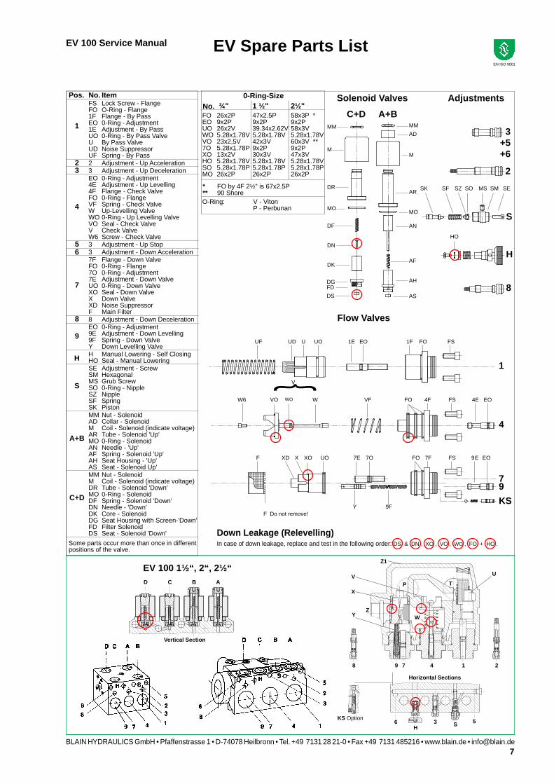
C+D A+B ¾" 1 ½" 2½"FO 26x2P 47x2.5P 58x3P *EO 9x2P 9x2P 9x2PUO 26x2V 39.34x2.62V 58x3VWO 5.28x1.78V 5.28x1.78V 5.28x1.78VVO 23x2,5V 42x3V 60x3V **7O 5.28x1.78P 9x2P 9x2PXO 13x2V 30x3V 47x3VHO 5.28x1.78V 5.28x1.78V 5.28x1.78VSO 5.28x1.78P 5.28x1.78P 5.28x1.78PMO 26x2P 26x2P 26x2P
O-Ring: V - Viton P - Perbunan
FD
2
VO WO W
{ V
Pos. No. Item FS Lock Screw - Flange FO O-Ring - Flange 1F Flange - By Pass EO 0-Ring - Adjustment 1E Adjustment - By Pass UO 0-Ring - By Pass Valve U By Pass Valve UD Noise Suppressor UF Spring - By Pass 2 Adjustment - Up Acceleration 3 Adjustment - Up Deceleration EO 0-Ring - Adjustment 4E Adjustment - Up Levelling 4F Flange - Check Valve FO 0-Ring - Flange VF Spring - Check Valve W Up-Levelling Valve WO 0-Ring - Up Levelling Valve VO Seal - Check Valve V Check Valve W6 Screw - Check Valve 3 Adjustment - Up Stop 3 Adjustment - Down Acceleration 7F Flange - Down Valve FO 0-Ring - Flange 7O 0-Ring - Adjustment 7E Adjustment - Down Valve UO 0-Ring - Down Valve XO Seal - Down Valve X Down Valve XD Noise Suppressor F Main Filter 8 Adjustment - Down Deceleration EO 0-Ring - Adjustment 9E Adjustment - Down Levelling 9F Spring - Down Valve Y Down Levelling Valve H Manual Lowering - Self Closing HO Seal - Manual Lowering SE Adjustment - Screw SM Hexagonal MS Grub Screw SO 0-Ring - Nipple SZ Nipple SF Spring SK Piston MM Nut - Solenoid AD Collar - Solenoid M Coil - Solenoid (indicate voltage) AR Tube - Solenoid 'Up' MO 0-Ring - Solenoid AN Needle - 'Up' AF Spring - Solenoid 'Up' AH Seat Housing - 'Up' AS Seat - Solenoid Up' MM Nut - Solenoid M Coil - Solenoid (indicate voltage) DR Tube - Solenoid 'Down' MO 0-Ring - Solenoid DF Spring - Solenoid 'Down' DN Needle - 'Down' DK Core - Solenoid DG Seat Housing with Screen-'Down' FD Filter Solenoid DS Seat - Solenoid 'Down'Some parts occur more than once in different positions of the valve.
EV Spare Parts List
Adjustments
In case of down leakage, replace and test in the following order: DS & DN , XO , VO , WO , FO + HO .
Flow Valves
F Do not remove!
Solenoid Valves0-Ring-SizeNo.
* FO by 4F 2½" is 67x2.5P** 90 Shore
Down Leakage (Relevelling)
V
X
Y
U
8 9 7 4 1 2
TP
Z1
Z
6H
3 S 5
D C B A
KS Option
EV 100 1½“, 2“, 2½“
Horizontal Sections
Vertical Section
W

8BLAIN HYDRAULICS GmbH • Pfaffenstrasse 1 • D-74078 Heilbronn • Tel. +49 7131 28 21-0 • Fax +49 7131 485216 • www.blain.de • [email protected]
EV 100 Service Manual
EN ISO 9001
A
EV 100 Trouble Shooting (2007)UP Travel
Up-Start
too hard
Possible cause Recommended Test: Turn adjustment 5 all the way in. If the elevator now starts upwards the problem is at solenoid A.
Solenoid A not energised or voltage too low.
Solenoid A tube not screwed down tight.
Solenoid valve A: Dirt or damage between needle AN and seat AS.
Adjustment 2 not far enough open.
Adjustment 1 too far back (open). Not enough pilot pressure.
Pressure relief S valve is set too low.
Adjustment 8 turned in too far (car sits on the buffer).
Bypass flow guide U is too large.
Pump running in the wrong direction.
The pump connection flange is leaking excessively.
The pump is undersize or worn. Test: If by turning adjustment 1 with the pump running the pressure does not rise above 5 bar, even with a smaller bypass valve inserted, the problem should be sought at the pump.
Test: Turn adjustment 3 all the way in. If the elevator now travels upwards at full speed the problem is at solenoid B.
Solenoid B not energised or voltage too low.
Solenoid B tube not screwed down tight.
Solenoid valve B: Dirt or damage between needle AN and seat AS.
The pump connection flange is leaking excessively.
The pump is undersize or worn. Test: If by turning adjustment 1 with the pump running the pressure does not rise above 5 bar, even with a smaller bypass valve inserted, the problem should be sought at the pump.
Adjustment 1 turned in too far.
Adjustment 2 turned out too far.
O-Ring UO on Bypass Valve U is leaking.
Star to Delta motor switch period is too long.
Excessive friction on the guide rails or in the cylinder head.
Solenoid B does not de-energise.
Adjustment 3 turned in too far.
O-Ring UO on Bypass Valve U is leaking.
Solenoid A is de-energised too late.
Adjustment 5 turned in too far.
Adjustment 1 turned in too far.
Up leveling speed too high.
Solenoid A and B reversed.
Up leveling speed too slow.
Middle O-Ring FO of flange 4F is leaking.
Relief valve is set too low.
See A below.
Tighten Solenoid A tube.
Clean or change needle and seat.
Turn out adjustment 2.
Turn in adjustment 1 with the pump running.
Set relief valve higher.
Turn out adjustment 8. Insert smaller bypass flow guide (see flow guide chartsat EV catalogue).
Install the pump correctly.
Seal the pump connection.
Select bigger pump or replace pump.
See A below.
Tighten Solenoid B tube.
Clean or change needle and seat.
Seal the pump connection.
Select bigger pump or replace pump.
Turn out adjustment 1.
Turn in adjustment 2.
Change O-Ring → see EV Spare Parts List.
0.2-0.3 sec. is sufficient.
Can not be eliminated thru valve adjustment.
Lift coil to check magnetic pull. See A below. Slow down switch possibly set to high (late).
Turn out adjustment 3. Turn in adjustment 2.
Change O-Ring → see EV Spare Parts List.
Lift coil to check pull. See A below.
Turn out adjustment 5.
Turn out adjustment 1.
Turn in adjustment 4 to about 0.05 m/s leveling speed.
Turn out adjustment 4.
Change O-Ring → see EV Spare Parts List.
Set relief valve higher.
No Up-Start
(Elevator
remains
at floor)
Up-Start, but
no Full Speed
Problem
No deceleration
into leveling
speed
Deceleration into leveling speed but overtravel of floor level
Elevator stops
before reaching
the floor
(no leveling)
Bypass-pressurenot adjustable Change to flow guide with wider slots.
For checking the operation of the solenoids, remove the top nuts. By lifting the coils a few millimeters, the magnetic pull of the coil can be felt. For testing, the operation of the elevator car can also be controlled by lifting and replacing the coil. If the coil gets too hot, the coil has to be mounted onto the solenoid and the following adjustments have to be carried out on normal travels from floor to floor.
Restriction on the return line.
Bypass flow guide U too small (slots too narrow).
Levelling too fast Adjustment 4 too far screwed out. Turn in adjustment 4 to about 0.05 m/s leveling speed.
Swap solenoid A and B. See A below.
Bypass flow guide U too small (slots too narrow). Change to flow guide with wider slots.
Remove restriction; enlarge return line.
Valves are fully adjusted and tested in the factory. Check electrical operation before changing valve setting.
Standard settings: Adjustments 1 & 4 approx. level with flange faces. Up to two turns in either direction may then be necessary. Adjustments 2, 3 & 5 all the way in (clockwise) then for EV ¾”: all adjustments 1.5 turns out (c-clockwise), for EV 1 1/2 “ – 2 ½”: adjustments 3 & 5 two and half turns out (c-clockwise), adjustment 2 two turns out. Small final adjustments may be necessary.

9BLAIN HYDRAULICS GmbH • Pfaffenstrasse 1 • D-74078 Heilbronn • Tel. +49 7131 28 21-0 • Fax +49 7131 485216 • www.blain.de • [email protected]
EV 100 Service Manual
EN ISO 9001
For possible down leakage points,see „Technical Dokumentation System Lenkage“.
Replace one seal at a time and test before proceeding tothe next point of possible leakage, if still necessary.
EV 100 Trouble Shooting (2007)DOWN Travel
Possible cause Recommended ProblemSolenoid D not energised or voltage too low.
Adjustment 6 turned in too far.
Adjustment 8 turned out too far.
O-Ring UO on Down Valve X is leaking.
Solenoid C not energised or voltage too low.
Adjustment 7 turned in too far.
Down Valve flow guide X too small.
Solenoid C and D reversed.
Adjustment 9 turned in too far.
Spring 9F in adjustment 9 is broken. Adjustment 8 turned in too far. Filter of adjustment 8blocked or adjustment 8 is damaged.Adjustment 9 turned out too far.
Solenoid valve C: Dirt or damage between needle DN and seat DS.
Inner O-Ring FO on flange 7F is leaking.
Solenoid D tube not screwed down tight.
Adjustment 8 turned in too far.
Solenoid valve D: Dirt or damage between needle DN and seat DS.
O-Ring XO of Down Valve X is leaking.
O-Ring VO of Check Valve V is leaking.
O-Ring WO of Leveling Valve W is leaking.
Inner O-Ring FO on flange 4F is leaking.
O-Ring HO of Manual Lowering H is leaking.
HP: Handpump is leaking.
HX/MX : Adjustment 8M turned in too far. HX/MX: Down valve 9M is leaking.Dirt or damage between the needle DN and seat DS.
HX/MX: O-Ring XO of Down Valve YM is leaking.
HX/MX: Manual Lowering is leaking (HX/MX).
Contraction of oil during cooling especially from 35°C or above.
No Down Start
No full speed
No downleveling. Elevator stops before floor level
No downleveling. Elevator travels though floor level
Elevator sinksquickly
Elevator sinksslowly due toinner leakage(Relevelling)
Lift coil to check magnetic pull. See A below.
Turn out adjustment 6. Turn in adjustment 8 cautiously.Attention: Danger of traveling through
Change O-Ring → see EV Spare Parts List.
Lift coil to check magnetic pull. See A below.
Turn out adjustment 7.
Check insert size (see flow guide charts page 6)
Lift coil to check magnetic pull. See A below.
Turn out adjustment 9 to about 0.05 m/s leveling speed.
Replace adjustment 9 complete.
Turn out adjustment 8 about ½ turn.
Turn in adjustment 9 to about 0.05 m/s leveling speed.
Clean or change needle and seat.
Change O-Ring → see EV Spare Parts List.
Tighten Solenoid D tube.
Turn out adjustment 8 about ½ turn.
Clean or change needle and seat. Change O-Ring → see EV Spare Parts List.When Down Valve is compensated, replace Down Valve.
Change Check Valve → see EV Spare Parts List.
Change O-Ring → see EV Spare Parts List.
Change O-Ring → see EV Spare Parts List.
Replace Manual Lowering. Remove suction tube and observe if handpump leaks.Replace complete hand pump.
Turn out adjustment 8M.
Clean or change needle and seat.
Change O-Ring → see EV Spare Parts List.
Replace Manual Lowering.
Consider oil cooler if hot oil is a problem.
Elevator sinksdue toinner leakageof auxiliary equipment
A For checking the operation of the solenoids, remove the top nuts. By lifting the coils a few millimeters, the magnetic pull of the coil can be felt. For testing, the operation of the elevator car can also be controlled by lifting and replacing the coil. If the coil gets too hot, the coil has to be mounted onto the solenoid and the following adjustments have to be carried out on normal travels from floor to floor.
Valves are fully adjusted and tested in the factory. Check electrical operation before changing valve setting.
Standard settings: Adjustments 7 & 9 approx. level with flange faces. Up to two turns in either direction may then be necessary. Adjustments 6 & 8 all the way in (clockwise) then for EV ¾”, adjustment 6,1 ½ turn and adjustment 8, 1 turn out (c-clockwise), for EV 1 1/2 “ – 2 ½”, adjustments 6 & 8, 1 ½ turns out (c-clockwise). Small final adjustments may be necessary.

10BLAIN HYDRAULICS GmbH • Pfaffenstrasse 1 • D-74078 Heilbronn • Tel. +49 7131 28 21-0 • Fax +49 7131 485216 • www.blain.de • [email protected]
EV 100 Service Manual
EN ISO 9001
Slack Rope Valve `K´
PurposeIn the case of the operation of the safeties in a 1:2 hydraulic lift system when the weight of the car is no longer carried by the ropes, the electrical supply to the elevator must automatically be switched off. The K Slack Rope Valve avoids the ram being lowered by the opening of the manual lowering valve which could otherwise cause a tangled rope condition. The K Slack Rope Valve prevents the pressure holding up the ram from being evacuated through the manual lowering valve.
FunctionThe K valve is adjusted to a pressure just above the pressure produced by the weight of the ram. When under normal oper-ating conditions, the weight of the car acts upon the ram through the 1:2 roping, the resulting pressure is suffi cient to open the poppet of the K valve when the manual lowering H is opened, allowing the car to descend as required. When however the `safeties´ have operated and only the weight of the ram and sheave block are acting upon the hydraulic system, the resulting pressure is too low to open the K valve. The ram and sheave block can not be lowered.
AdjustmentThe K is adjusted with a 3 mm Socket Key by turning the screw K `in´ for higher pressure and `out´ for lower pressure. With K turned all the way `in´, then half a turn back out, the unloaded car should descend when the D solenoid alone is energised. Should the car not descend, K must be backed off until the car just begins to descend, then backed off a further half turn to ensure that with cold oil, the car can be lowered as required.
Lock Screw K 2
Adjustment Screw K
Adjustment Screw K
Down Flange 7 - 9
Plug Screw K 6
6 mm Ball K 5
Spring K 4
0-Ring K 3
Adjustment 9
K
Manual lowering H
11BLAIN HYDRAULICS GmbH • Pfaffenstrasse 1 • D-74078 Heilbronn • Tel. +49 7131 28 21-0 • Fax +49 7131 485216 • www.blain.de • [email protected]
EV 100 Service Manual
EN ISO 9001
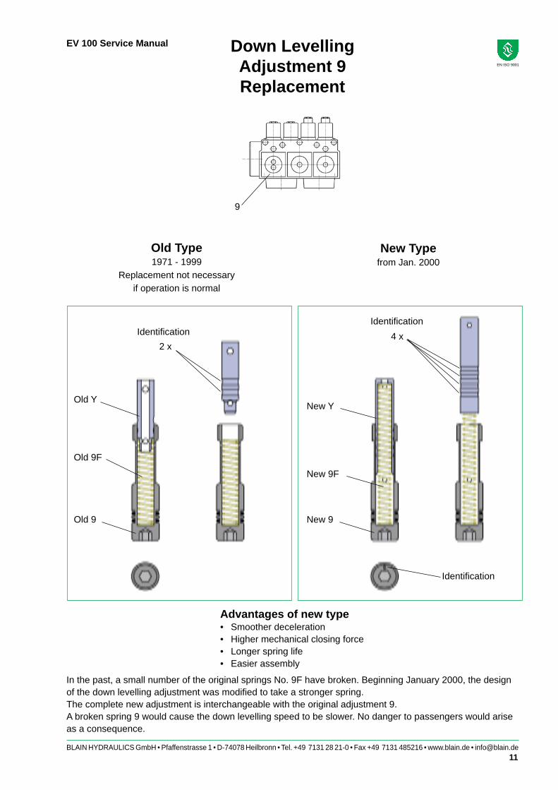
Down Levelling Adjustment 9Replacement
Old Type1971 - 1999
Replacement not necessaryif operation is normal
New Typefrom Jan. 2000
Advantages of new type• Smoother deceleration• Higher mechanical closing force• Longer spring life• Easier assembly
Identifi cation
Identifi cationIdentifi cation
Old Y
Old 9F
Old 9
New Y
New 9F
New 9
2 x4 x
In the past, a small number of the original springs No. 9F have broken. Beginning January 2000, the design of the down levelling adjustment was modifi ed to take a stronger spring. The complete new adjustment is interchangeable with the original adjustment 9.A broken spring 9 would cause the down levelling speed to be slower. No danger to passengers would arise as a consequence.
9

12BLAIN HYDRAULICS GmbH • Pfaffenstrasse 1 • D-74078 Heilbronn • Tel. +49 7131 28 21-0 • Fax +49 7131 485216 • www.blain.de • [email protected]
EV 100 Service Manual
EN ISO 9001
Overheating of Power Units - System Leakage
Oil temperatures above 55 °C (130° F) should be avoided, otherwise the effi ciency of the pump drops considerably and its life is reduced. Aging of the oil is also accelerated.
Possible causes of overheating:1. Up levelling too long due to the levelling speed being too slow or the slow down switch being set too low.2. Machine room ventilation inadequate.3. The frequency of operation is too high for the normal rate of heat dissipation.
Temporary solution:As a temporary measure to avoid overheating of the oil resulting in the shut down of the elevator, the down speed can be slowed to reduce frequency of operation until a permanent solution is installed.
Cooling systemsa. If the degree of overheating is not excessive and it takes for example two to three hours for the oil temperature to rise
from 20° to 55°C (70° to 130° F), it may be suffi cient to improve air circulation around the power unit, for example through the installation of a 0.05 to 0.10 kW ventilator extracting air out of the machine room or through a fan of similar power, blowing air over the power unit.
b. Should the above be inadequate, depending on the size of the elevator, it will be necessary to install a 10-50 l/min. (3 - 13 gpm) pump to circulate the hot oil through an air cooled radiator of about 0.1 to 0.2 fan kW. It is also essential that there is suffi cient extraction of warm air out of the machine room or that the cooler is out side of the machine room, for example in the elevator shaft. The effective cooling power of an air cooled radiator should not to be confused with the power of the fan drive which normally need only be 0.1 or 0.2 kW. Normally, the effective cooling power of a cooler need only be approximately ¼ of the main hydraulic elevator motor, in the case of submersible drives.
Cooling systems for the above purpose should be switched into operation when the oil reaches 30° - 35°C (85° - 95° F).
System leakage (re-levelling)The aim of manufacturers of hydraulic elevator control valves is to produce valves with zero leakage. Due to fi ne con-tamination in the oil perfect sealing between valve parts may not always be achieved, leading to a slow down leak of the elevator car.
It would become unnecessarily expensive to strive for perfect sealing in every valve in operation. Therefore, because code requirements assure a safe relevelling system whether descent of the car is caused by valve leakage or through the cooling of the oil in the cylinder pressure system, a minor leakage of the control valve can be tolerated.
1. The European Code EN 81-2 require: that the loaded elevator does not leak downwards by more than 10 mm (3/8“) in 10 minutes. This is the standard used to determine if a valve should be serviced for leakage.
2. For practical reasons, a quicker method for judging valve leakage is to close the ball valve in the cylinder line and observe the gauge showing pressure in the cylinder chamber of the valve. If this pressure falls to zero in less than 20 secs, it may be necessary to service the valve, depending on the diameter of the main ram and sensitivity of the customer.
3. Down sinking giving the impression of leakage can be due to cooling of the oil.
When the elevator is at rest and the temperature of the oil falls, contraction of the oil in the cylinder and piping causes the car to sink. This sinking is very slow but overnight without relevelling could amount to as much as half a meter, depending on the temperature drop of the oil and the volume of oil in the cylinder system. The elevator relevelling system, operating normally however, keeps the car at fl oor level.
4. In the case of Blain EV valves, see page 6 indicating where valve down leakage can occur.
13BLAIN HYDRAULICS GmbH • Pfaffenstrasse 1 • D-74078 Heilbronn • Tel. +49 7131 28 21-0 • Fax +49 7131 485216 • www.blain.de • [email protected]
EV 100 Service Manual
EN ISO 9001
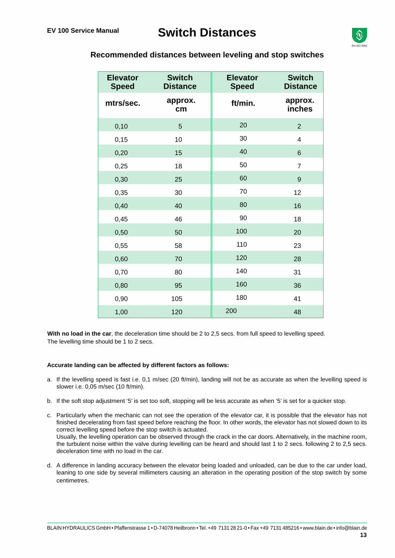
Recommended distances between leveling and stop switches
Accurate landing can be affected by different factors as follows:
a. If the levelling speed is fast i.e. 0,1 m/sec (20 ft/min), landing will not be as accurate as when the levelling speed is slower i.e. 0,05 m/sec (10 ft/min).
b. If the soft stop adjustment ‘5’ is set too soft, stopping will be less accurate as when ‘5’ is set for a quicker stop.
c. Particularly when the mechanic can not see the operation of the elevator car, it is possible that the elevator has not fi nished decelerating from fast speed before reaching the fl oor. In other words, the elevator has not slowed down to its correct levelling speed before the stop switch is actuated.
Usually, the levelling operation can be observed through the crack in the car doors. Alternatively, in the machine room, the turbulent noise within the valve during levelling can be heard and should last 1 to 2 secs. following 2 to 2,5 secs. deceleration time with no load in the car.
d. A difference in landing accuracy between the elevator being loaded and unloaded, can be due to the car under load, leaning to one side by several millimeters causing an alteration in the operating position of the stop switch by some centimetres.
Switch Distances
mtrs/sec.
0,10 5 2
0,15 10 4
0,20 15 6
0,25 18 7
0,30 25 9
0,35 30 12
0,40 40 16
0,45 46 18
0,50 50 20
0,55 58 23
0,60 70 28
0,70 80 31
0,80 95 36
0,90 105 41
1,00 120 48
With no load in the car, the deceleration time should be 2 to 2,5 secs. from full speed to levelling speed. The levelling time should be 1 to 2 secs.
Elevator Speed
Elevator Speed
Switch Distance
Switch Distance
20
30
40
50
60
70
80
90
100
110
120
140
160
180
200
approx. cm
approx. inches
ft/min.

14BLAIN HYDRAULICS GmbH • Pfaffenstrasse 1 • D-74078 Heilbronn • Tel. +49 7131 28 21-0 • Fax +49 7131 485216 • www.blain.de • [email protected]
EV 100 Service Manual
EN ISO 9001 ISO 9001
kg 500 750 1000 1500 2000 2500 3000 3500 4000 4500 5000 6000 7000 8000 9000 10000
Ø mm cm² bar
35 9,6 51 76 102 153 204 255 306 357 408 459 510 612 714 816 918 1020
40 12,6 39 59 78 117 156 195 234 273 312 351 390 468 546 625 703 781
45 15,9 31 46 62 93 123 154 185 216 247 278 308 370 432 493 555 617
50 19,6 25 38 50 75 100 125 150 175 200 225 250 300 350 400 450 500
55 23,8 21 31 41 62 83 103 124 145 165 186 206 248 289 330 372 413
60 28,3 17 26 35 52 69 87 104 121 139 156 173 208 243 278 312 347
65 33,2 15 22 30 44 59 74 89 103 118 133 148 177 207 237 266 296
70 38,5 13 19 26 38 51 64 76 89 102 115 127 153 178 204 229 255
75 44,2 11 17 22 33 44 56 67 78 89 100 111 133 155 178 200 222
80 50,3 9,8 15 20 29 39 49 59 68 78 88 98 117 137 156 176 195
85 56,7 8,6 13 17 26 35 43 52 61 69 78 86 104 121 138 156 173
90 63,6 7,7 12 15 23 31 39 46 54 62 69 77 93 108 123 139 154
95 70,9 6,9 10 14 21 28 35 42 48 55 62 69 83 97 111 125 138
100 78,5 6,2 9,4 13 19 25 31 38 44 50 56 62 75 87 100 112 125
105 86,6 5,7 8,5 11 17 23 28 34 40 45 51 57 68 79 91 102 113
110 95,0 5,2 7,7 10 16 21 26 31 36 41 47 52 62 72 83 93 103
115 103,9 4,7 7,1 9,4 14 19 24 28 33 38 43 47 57 66 76 85 94
120 113,1 4,3 6,5 8,7 13 17 22 26 30 35 39 43 52 61 69 78 87
125 122,7 4,0 6,0 8,0 12 16 20 24 28 32 36 40 48 56 64 72 80
130 132,7 3,7 5,5 7,4 11 15 19 22 26 30 33 37 44 52 59 67 74
140 153,9 3,2 4,8 6,4 9,6 13 16 19 22 26 29 32 38 45 51 57 64
150 176,7 2,8 4,2 5,6 8,3 11 14 17 19 22 25 28 33 39 44 50 56
160 201,1 2,4 3,7 4,9 7,3 9,8 12 15 17 20 22 24 29 34 39 44 49
170 227,0 2,2 3,2 4,3 6,5 8,6 11 13 15 17 19 22 26 30 35 39 43
180 254,5 1,9 2,9 3,9 5,8 7,7 9,6 12 14 15 17 19 23 27 31 35 39
190 283,5 1,7 2,6 3,5 5,2 6,9 8,6 10 12 14 16 17 21 24 28 31 35
200 314,2 1,6 2,3 3,1 4,7 6,2 7,8 9,4 11 13 14 16 19 22 25 28 31
210 346,4 1,4 2,1 2,8 4,2 5,7 7,1 8,5 9,9 11 13 14 17 20 23 26 28
220 380,1 1,3 1,9 2,6 3,9 5,2 6,5 7,7 9,0 10,3 12 13 16 18 21 23 26
240 452,4 1,1 1,6 2,2 3,3 4,3 5,4 6,5 7,6 8,7 9,8 11 13 15 17 20 22
260 530,9 0,9 1,4 1,8 2,8 3,7 4,6 5,5 6,5 7,4 8,3 9,2 11 13 15 17 19
280 615,8 0,8 1,2 1,6 2,4 3,2 4,0 4,8 5,6 6,4 7,2 8,0 9,6 11 13 14 16
300 706,9 0,7 1,0 1,4 2,1 2,8 3,5 4,2 4,9 5,6 6,2 6,9 8,3 9,7 11 13 14
m/sec. 0,05 0,10 0,15 0,20 0,25 0,30 0,35 0,40 0,45 0,50 0,55 0,60 0,70 0,80 0,90 1,00
Ø mm cm² l/min.
35 9,6 2,9 5,8 8,7 11,5 14 17 20 23 26 29 32 35 40 46 52 58
40 12,6 3,8 7,5 11,3 15,1 19 23 26 30 34 38 41 45 53 60 68 75
45 15,9 4,8 9,5 14,3 19,1 24 29 33 38 43 48 52 57 67 76 86 95
50 19,6 5,9 11,8 17,7 23,6 29 35 41 47 53 59 65 71 82 94 106 118
55 23,8 7,1 14,3 21,4 28,5 36 43 50 57 64 71 78 86 100 114 128 143
60 28,3 8,5 17,0 25,4 33,9 42 51 59 68 76 85 93 102 119 136 153 170
65 33,2 10,0 19,9 29,9 39,8 50 60 70 80 90 100 110 119 139 159 179 199
70 38,5 11,5 23,1 34,6 46,2 58 69 81 92 104 115 127 139 162 185 208 231
75 44,2 13,3 26,5 39,8 53,0 66 80 93 106 119 133 146 159 186 212 239 265
80 50,3 15,1 30,2 45,2 60,3 75 90 106 121 136 151 166 181 211 241 271 302
85 56,7 17,0 34,0 51,1 68,1 85 102 119 136 153 170 187 204 238 272 306 340
90 63,6 19,1 38,2 57,3 76,3 95 115 134 153 172 191 210 229 267 305 344 382
95 70,9 21,3 42,5 63,8 85,1 106 128 149 170 191 213 234 255 298 340 383 425
100 78,5 23,6 47,1 70,7 94,2 118 141 165 188 212 236 259 283 330 377 424 471
105 86,6 26,0 52,0 77,9 103,9 130 156 182 208 234 260 286 312 364 416 468 520
110 95,0 28,5 57,0 85,5 114,0 143 171 200 228 257 285 314 342 399 456 513 570
115 103,9 31,2 62,3 93,5 124,6 156 187 218 249 280 312 343 374 436 499 561 623
120 113,1 33,9 67,9 101,8 135,7 170 204 238 271 305 339 373 407 475 543 611 679
125 122,7 36,8 73,6 110,4 147,3 184 221 258 295 331 368 405 442 515 589 663 736
130 132,7 39,8 79,6 119,5 159,3 199 239 279 319 358 398 438 478 557 637 717 796
140 153,9 46,2 92,4 138,5 184,7 231 277 323 369 416 462 508 554 647 739 831 924
150 176,7 53,0 106,0 159,0 212,1 265 318 371 424 477 530 583 636 742 848 954 1060
160 201,1 60,3 120,6 181,0 241,3 302 362 422 483 543 603 664 724 844 965 1086 1206
170 227,0 68,1 136,2 204,3 272,4 340 409 477 545 613 681 749 817 953 1090 1226 1362
180 254,5 76,3 152,7 229,0 305,4 382 458 534 611 687 763 840 916 1069 1221 1374 1527
190 283,5 85,1 170,1 255,2 340,2 425 510 595 680 766 851 936 1021 1191 1361 1531 1701
200 314,2 94,2 188,5 282,7 377,0 471 565 660 754 848 942 1037 1131 1319 1508 1696 1885
210 346,4 103,9 207,8 311,7 415,6 520 623 727 831 935 1039 1143 1247 1455 1663 1870 2078
220 380,1 114,0 228,1 342,1 456,2 570 684 798 912 1026 1140 1254 1368 1597 1825 2053 2281
240 452,4 135,7 271,4 407,2 542,9 679 814 950 1086 1221 1357 1493 1629 1900 2171 2443 2714
260 530,9 159,3 318,6 477,8 637,1 796 956 1115 1274 1434 1593 1752 1911 2230 2548 2867 3186
280 615,8 184,7 369,5 554,2 738,9 924 1108 1293 1478 1663 1847 2032 2217 2586 2956 3325 3695
300 706,9 212,1 424,1 636,2 848,2 1060 1272 1484 1696 1909 2121 2333 2545 2969 3393 3817 4241
Ram Ø • Area • Load • Pressure
Ram Ø • Area • Speed • Flow
Flow - Pressure Tables (metric)
= in²cm²6,45
= inchesmm
25,4m/sec x 197 = ft/min. l/min. x 0,22 = Imp. gals l/min x 0,26 = US. gals kg x 2,2 = lbs bar x 14,7 = psi
Piston Ø • Aire • Vitesse • Débit Pistón Ø • Area • Velocidad • Caudal
Kolben Ø • Fläche • Geschwindigkeit • Durchfluss
Piston Ø • Aire • Cargaision • Pression
Kolben Ø • Fläche • Gewicht • Druck
Pistón Ø • Area • Carga • Presión
US gpm.US gpm. 5 10 15 20 25 30 35
20 40 60 80 100 120 140
50 100 150 200 250 300 350 400 20 40 60 80 100 120 140 160 180 200
200 400 600 800 1000 1200 1400 1600 100 200 300 400 500 600 700
01 02 03 04
06
05 0 1 2 3 4 5
6
8 9
10
1 ½" & 2" 2 ½"¾" US gpm.
l/min. l/min. l/min.
50
40
30
20
10
0
700
600
500
400
300
200
100
50
40
30
20
10
0
700
600
500
400
300
200
100
50
40
30
20
10
0
700
600
500
400
300
200
100
bar psi psi barbar psi
Stat
ic p
ress
ure
with
em
pty
car.
Stat
ic p
ress
ure
with
em
pty
car.
Stat
ic p
ress
ure
with
em
pty
car.
Stat
ic p
ress
ure
with
em
pty
car.
Flow Guide Selection Charts
15BLAIN HYDRAULICS GmbH • Pfaffenstrasse 1 • D-74078 Heilbronn • Tel. +49 7131 28 21-0 • Fax +49 7131 485216 • www.blain.de • [email protected]
EV 100 Service Manual
EN ISO 9001
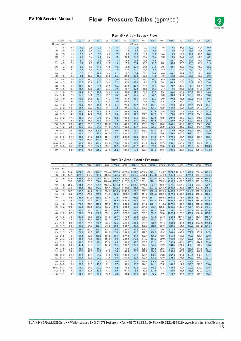
Flow - Pressure Tables (gpm/psi)
ft/min 10 20 30 40 50 60 70 80 90 100 110 120 140 160 180 200
Ø inch in² US gpm
1,4 1,5 0,8 1,6 2,4 3,2 4,0 4,8 5,6 6,4 7,2 8,0 8,8 9,6 11,2 12,8 14,4 16,0
1,6 2,0 1,0 2,1 3,1 4,2 5,2 6,3 7,3 8,4 9,4 10,5 11,5 12,5 14,6 16,7 18,8 20,9
1,8 2,5 1,3 2,6 4,0 5,3 6,6 7,9 9,3 10,6 11,9 13,2 14,6 15,9 18,5 21,2 23,8 26,5
2,0 3,1 1,6 3,3 4,9 6,5 8,2 9,8 11,4 13,1 14,7 16,3 18,0 19,6 22,9 26,1 29,4 32,7
2,2 3,8 2,0 4,0 5,9 7,9 9,9 11,9 13,8 15,8 17,8 19,8 21,7 23,7 27,7 31,6 35,6 39,5
21/2 4,9 2,6 5,1 7,7 10,2 12,8 15,3 17,9 20,4 23,0 25,5 28,1 30,6 35,7 40,8 45,9 51,0
2,6 5,3 2,8 5,5 8,3 11,0 13,8 16,6 19,3 22,1 24,8 27,6 30,4 33,1 38,6 44,2 49,7 55,2
23/4 5,9 3,1 6,2 9,3 12,4 15,4 18,5 21,6 24,7 27,8 30,9 34,0 37,1 43,2 49,4 55,6 61,8
3,0 7,1 3,7 7,3 11,0 14,7 18,4 22,0 25,7 29,4 33,1 36,7 40,4 44,1 51,4 58,8 66,1 73,5
3,2 8,0 4,2 8,4 12,5 16,7 20,9 25,1 29,3 33,4 37,6 41,8 46,0 50,2 58,5 66,9 75,3 83,6
31/2 9,6 5,0 10,0 15,0 20,0 25,0 30,0 35,0 40,0 45,0 50,0 55,0 60,0 70,0 80,0 90,0 100,0
3,6 10,2 5,3 10,6 15,9 21,2 26,5 31,7 37,0 42,3 47,6 52,9 58,2 63,5 74,1 84,7 95,2 105,8
3,8 11,3 5,9 11,8 17,7 23,6 29,5 35,4 41,3 47,2 53,1 59,0 64,9 70,7 82,5 94,3 106,1 117,9
4,0 12,6 6,5 13,1 19,6 26,1 32,7 39,2 45,7 52,3 58,8 65,3 71,9 78,4 91,5 104,5 117,6 130,7
4,2 13,9 7,2 14,4 21,6 28,8 36,0 43,2 50,4 57,6 64,8 72,0 79,2 86,4 100,8 115,2 129,6 144,0
43/8 15,0 7,8 15,6 23,4 31,3 39,1 46,9 54,7 62,5 70,3 78,1 86,0 93,8 109,4 125,0 140,7 156,3
41/2 15,9 8,3 16,5 24,8 33,1 41,3 49,6 57,9 66,1 74,4 82,7 90,9 99,2 115,8 132,3 148,8 165,4
4,8 18,1 9,4 18,8 28,2 37,6 47,0 56,4 65,8 75,3 84,7 94,1 103,5 112,9 131,7 150,5 169,3 188,1
5,0 19,6 10,2 20,4 30,6 40,8 51,0 61,2 71,5 81,7 91,9 102,1 112,3 122,5 142,9 163,3 183,7 204,1
57/16 23,2 12,1 24,1 36,2 48,3 60,4 72,4 84,5 96,6 108,6 120,7 132,8 144,9 169,0 193,1 217,3 241,4
51/2 23,8 12,4 24,7 37,1 49,4 61,8 74,1 86,5 98,8 111,2 123,5 135,9 148,2 172,9 197,6 222,3 247,0
6,0 28,3 14,7 29,4 44,1 58,8 73,5 88,2 102,9 117,6 132,3 147,0 161,7 176,4 205,8 235,2 264,6 294,0
61/2 33,2 17,3 34,5 51,8 69,0 86,3 103,5 120,8 138,0 155,3 172,5 189,8 207,0 241,5 276,0 310,5 345,0
6,8 36,3 18,9 37,8 56,6 75,5 94,4 113,3 132,2 151,0 169,9 188,8 207,7 226,6 264,3 302,1 339,8 377,6
7,0 38,5 20,0 40,0 60,0 80,0 100,0 120,0 140,0 160,1 180,1 200,1 220,1 240,1 280,1 320,1 360,1 400,1
71/2 44,2 23,0 45,9 68,9 91,9 114,8 137,8 160,8 183,7 206,7 229,7 252,6 275,6 331,5 367,5 413,4 459,3
8,0 50,3 26,1 52,3 78,4 104,5 130,7 156,8 182,9 209,0 235,2 261,3 287,4 313,6 365,8 418,1 470,4 522,6
81/2 56,7 29,5 59,0 88,5 118,0 147,5 177,0 206,5 236,0 265,5 295,0 324,5 354,0 413,0 472,0 531,0 590,0
8,8 60,8 31,6 63,2 94,9 126,5 158,1 189,7 221,3 252,9 284,6 316,2 347,8 379,4 442,7 505,9 569,1 632,4
91/2 70,9 36,8 73,7 110,5 147,4 184,2 221,1 257,9 294,8 331,6 368,5 405,3 442,2 515,9 589,6 663,3 737,0
105/8 88,7 46,1 92,2 138,3 184,4 230,5 276,6 322,6 368,7 414,8 460,9 507,0 553,1 645,3 737,5 829,7 921,9
11,2 98,5 51,2 102,4 153,6 204,9 256,1 307,3 358,5 409,7 460,9 512,2 563,4 614,6 717,0 819,5 921,9 1024,3
12,0 113,1 58,8 117,6 176,4 235,2 294,0 352,8 411,6 470,4 529,1 587,9 646,7 705,5 823,1 940,7 1058,3 1175,9
lbs 1100 1650 2200 3300 4400 5500 6600 7700 8800 10000 11000 13200 15400 17600 19800 22000
Ø inch in² psi
1,4 1,5 714,6 1071,9 1429,1 2143,7 2858,3 3572,9 4287,4 5002,0 5716,6 6496,1 7145,7 8574,9 10004,0 11433,2 12862,3 14291,5
1,6 2,0 547,1 820,6 1094,2 1641,3 2188,4 2735,5 3282,6 3829,7 4376,8 4973,6 5471,0 6565,1 7659,3 8753,5 9847,7 10941,9
1,8 2,5 432,3 648,4 864,5 1296,8 1729,1 2161,4 2593,6 3025,9 3458,2 3929,8 4322,7 5187,3 6051,8 6916,4 7780,9 8645,5
2,0 3,1 350,1 525,2 700,3 1050,4 1400,6 1750,7 2100,8 2451,0 2801,1 3183,1 3501,4 4201,7 4902,0 5602,3 6302,5 7002,8
2,2 3,8 289,4 434,1 578,7 868,1 1157,5 1446,9 1736,2 2025,6 2315,0 2630,7 2893,7 3472,5 4051,2 4630,0 5208,7 5787,5
21/2 4,9 224,1 336,1 448,2 672,3 896,4 1020,5 1344,5 1568,6 1792,7 2037,2 2240,9 2689,1 3137,3 3585,4 4033,6 4481,8
2,6 5,3 207,2 310,8 414,4 621,6 828,7 1035,9 1243,1 1450,3 1657,5 1883,5 2071,8 2486,2 2900,6 3314,9 3729,3 4143,7
23/4 5,9 185,2 277,8 370,4 555,6 740,8 926,0 1111,2 1296,4 1481,6 1683,6 1852,0 2222,4 2592,8 2963,2 3333,6 3704,0
3,0 7,1 155,6 233,4 311,2 466,9 622,5 778,1 933,7 1089,3 1244,9 1414,7 1556,2 1867,4 2178,7 2489,9 2801,1 3112,4
3,2 8,0 136,8 205,2 273,5 410,3 547,1 683,9 820,6 957,4 1094,2 1243,4 1367,7 1641,3 1914,8 2188,4 2461,9 2735,5
31/2 9,6 114,3 171,5 228,7 343,0 457,3 571,7 686,0 800,3 914,7 1039,4 1143,3 1372,0 1600,6 1829,3 2058,0 2286,6
3,6 10,2 108,1 162,1 216,1 324,2 432,3 540,3 648,4 756,5 864,5 982,4 1080,7 1296,8 1513,0 1729,1 1945,2 2161,4
3,8 11,3 97,0 145,5 194,0 291,0 388,0 485,0 582,0 678,9 775,9 881,7 969,9 1163,9 1357,9 1551,9 1745,9 1939,8
4,0 12,6 87,5 131,3 175,1 262,6 350,1 437,7 525,2 612,7 700,3 795,8 875,4 1050,4 1225,5 1400,6 1575,6 1750,7
4,2 13,9 79,4 119,1 158,8 238,2 317,6 397,0 476,4 555,8 635,2 721,8 794,0 952,8 1111,6 1270,4 1429,1 1587,9
43/8 15,0 73,2 109,8 146,3 219,5 292,7 365,9 439,0 512,2 585,4 665,2 731,7 878,1 1024,4 1170,8 1317,1 1463,4
41/2 15,9 69,2 103,7 138,3 207,5 276,7 345,8 415,0 484,1 553,3 628,8 691,6 830,0 968,3 1106,6 1244,9 1383,3
4,8 18,1 60,8 91,2 121,6 182,4 243,2 303,9 364,7 425,5 486,3 552,6 607,9 729,5 851,0 972,6 1094,2 1215,8
5,0 19,6 56,0 84,0 112,0 168,1 224,1 280,1 336,1 392,2 448,2 509,3 560,2 672,3 784,3 896,4 1008,4 1120,5
57/16 23,2 47,4 71,1 94,7 142,1 189,5 236,9 284,2 331,6 379,0 430,6 473,7 568,4 663,2 757,9 852,7 947,4
51/2 23,8 46,3 69,4 92,6 138,9 185,2 231,5 277,8 324,1 370,4 420,9 463,0 555,6 648,2 740,8 833,4 926,0
6,0 28,3 38,9 58,4 77,8 116,7 155,6 194,5 233,4 272,3 311,2 353,7 389,0 466,9 544,7 622,5 700,3 778,1
61/2 33,2 33,1 49,7 66,3 99,4 132,6 165,7 198,9 232,0 265,2 301,4 331,5 397,8 464,1 530,4 596,7 663,0
6,8 36,3 30,3 45,4 60,6 90,9 121,2 151,4 181,7 212,0 242,3 275,4 302,9 363,5 424,0 484,6 545,2 605,8
7,0 38,5 28,6 42,9 57,2 85,7 114,3 142,9 171,5 200,1 228,7 259,8 285,8 343,0 400,2 457,3 514,5 571,7
71/2 44,2 24,9 37,3 49,8 74,7 99,6 124,5 149,4 174,3 199,2 226,4 249,0 298,8 348,6 398,4 448,2 498,0
8,0 50,3 21,9 32,8 43,8 65,7 87,5 109,4 131,3 153,2 175,1 198,9 218,8 262,6 306,4 350,1 393,9 437,7
81/2 56,7 19,4 29,1 38,8 58,2 77,5 96,9 116,3 135,7 155,1 176,2 193,8 232,6 271,4 310,2 348,9 387,7
8,8 60,8 18,1 27,1 36,2 54,3 72,3 90,4 108,5 126,6 144,7 164,4 180,9 217,0 253,2 289,4 325,5 361,7
91/2 70,9 15,5 23,3 31,0 46,6 62,1 77,6 93,1 108,6 124,1 141,1 155,2 186,2 217,3 248,3 279,3 310,4
105/8 88,7 12,4 18,6 24,8 37,2 49,6 62,0 74,4 86,8 99,3 112,8 124,1 148,9 173,7 198,5 223,3 248,1
11,2 98,5 11,2 16,7 22,3 33,5 44,7 55,8 67,0 78,2 89,3 101,5 111,7 134,0 156,3 178,6 201,0 223,3
12,0 113,1 9,7 14,6 19,5 29,2 38,9 48,6 58,4 68,1 77,8 88,4 97,3 116,7 136,2 155,6 175,1 194,5
Ram Ø • Area • Load • Pressure
Ram Ø • Area • Speed • Flow