Elevate Window Installation - Marvin Installation.pdf · Unlocked windows can open during...
15
2020-01-08 19970163 Elevate Window Installation New Wood Frame Construction Introduction These instructions are applicable for the following window products: • Casement Family • Double Hung Family • Round Top • Polygon • Glider ABSTRACT: Please read these instructions in their entirety before beginning to install your Integrity window prod- uct. These installation instructions demonstrate the installation of a Elevate window in new wood frame construction using an industry approved water management system. For installation using other construction methods, such as remodeling, replacement, and recessed openings refer to “ASTM E2112-01, Standard Practice for Installation of Ex- terior Windows, Doors and Skylights,” for installation suggestions. Information for ASTM E2112 can be found on the ASTM website, www.astm.org. For product specific issues, service instructions and other field service guides, refer to the Integrity Service Manual, visit our website at www.marvin.com, or contact your Marvin representative. Regional standard practices, environmental conditions, and codes may vary and supersede the procedures con- tained within. The responsibility for compliance is yours: the installer, inspector, and owner(s). The procedures within these instructions are consistent with those used in testing to achieve the advertised DP rat- ing. The English language version of this Elevate Installation Instruction is the official version and shall take precedence over any translation
Transcript of Elevate Window Installation - Marvin Installation.pdf · Unlocked windows can open during...

2020-01-0819970163
Elevate Window InstallationNew Wood Frame Construction
IntroductionThese instructions are applicable for the following window products:
• Casement Family
• Double Hung Family
• Round Top
• Polygon
• Glider
ABSTRACT: Please read these instructions in their entirety before beginning to install your Integrity window prod-uct. These installation instructions demonstrate the installation of a Elevate window in new wood frame constructionusing an industry approved water management system. For installation using other construction methods, such asremodeling, replacement, and recessed openings refer to “ASTM E2112-01, Standard Practice for Installation of Ex-terior Windows, Doors and Skylights,” for installation suggestions. Information for ASTM E2112 can be found on theASTM website, www.astm.org.
For product specific issues, service instructions and other field service guides, refer to the Integrity Service Manual,visit our website at www.marvin.com, or contact your Marvin representative.
Regional standard practices, environmental conditions, and codes may vary and supersede the procedures con-tained within. The responsibility for compliance is yours: the installer, inspector, and owner(s).
The procedures within these instructions are consistent with those used in testing to achieve the advertised DP rat-ing.
The English language version of this Elevate Installation Instruction is the official version and shall take precedenceover any translation

2020-01-08 2 Elevate Window Installation19970163 New Wood Frame Construction
WARNINGAlways practice safety! Wear the appropriate eye, ear and hand protection, especially when working with powertools.
WARNINGThis product can expose you to chemicals including methanol, which is known to the state of California to causebirth defects or other reproductive harm. For more information, go to www.P65Warnings.ca.gov.
WARNINGThis product can expose you to chemicals including titanium oxide, which is known to the state of California to causecancer. For more information, go to www.P65Warnings.ca.gov.
WARNINGDrilling, sawing, sanding or machining wood products can expose you to wood dust, a substance known to the Stateof California to cause cancer. Avoid inhaling wood dust or use a dust mask or other safeguards for personal protec-tion. For more information go to www.P65Warnings.ca.gov/wood.
I M P O R TA N T
Please consult with local authorities to properly dispose and/or recycle all packaging, materials, and waste.
Table of ContentsInstaller and Builder Information ................................. 3After Market Products ................................................. 3Standard Parts Shipped.............................................. 3You Will Need to Supply.............................................. 3Rough and Masonry Opening Requirements.............. 4Rough Opening Preparation ....................................... 5Preparing the Unit for Installation................................ 6Installing the Window .................................................. 8Flashing the Installation - Air Barrier Applications......11Insulating and Sealing the Installation ...................... 12Final Installation Procedures..................................... 12Final Installation Procedures..................................... 14Technical Installation Specifications.......................... 15

2020-01-08 3 Elevate Window Installation19970163 New Wood Frame Construction
Installer and Builder Information• Always provide a copy of these instructions for the
current building owner.
• Plan sizing of rough opening and clearance from exterior finishing systems to allow for normal materials shrinkage or shifting (e.g. wood structure with brick veneer; allow adequate clearance at sill). Failure to do so can void the Integrity warranty coverage.
• Refer to the Technical Installation Specifications section for technical specifications regarding the installation of this product. These installation requirements as well as the details in this section must be followed to achieve the advertised design press (DP) rating of this product.
• It is the responsibility of the builder, installer and subcontractors to protect the interior and exterior of windows or doors from contact with harsh chemical
washes, construction material contamination and moisture. Damage to glazing, hardware, weather strip and cladding/wood can occur. Protect with painters tape and/or protective sheathing as required. Follow all guidelines regarding material use, preparation, personal safety and disposal.
• Refer to the enclosed painting and staining instructions on the last page for exterior and interior finish instructions.
• Contact your Marvin supplier if you have any questions regarding product and materials used in manufacturing or questions on replacement parts.
• Please refer to the PDF version of this instruction for further information regarding best practices, installer and builder information, code, and other legal requirements. The PDF version is the official document of record
After Market ProductsAlterations to Marvin products including window films, insulating or reflective interior window treatments or additionalglazings can cause excessive heat buildup and/or condensation. They may lead to premature failures not coveredunder warranty by Marvin Windows and Doors.
Before purchasing or applying any product that may affect the installation or performance of Integrity windows con-tact the manufacturer of after market product/glazings that are not supplied by Marvin and request written productuse, associated warranties and damage coverage. Provide this information and warranties to the end user and/orbuilding owner for future reference.
Standard Parts ShippedUnits are sent with hardware and four (4) nailing fin corner gaskets. Follow installation instructions included with part.
Note: Numbers listed in parentheses ( ) are metric equivalents in millimeters rounded to the nearest whole number
You Will Need to Supply• Safety Glasses
• Hearing protection
• Level
• Square
• Hammer
• Wood shims
• 2" Roofing Nails
• Insulation
• Tape Measure
• Perimeter Sealant
• Sill Pan Flashing
• Backing Material (foam backing rod)
• Low Expansion Foam Insulation
• Flashing Materials
• Weather Resistive Barrier

2020-01-08 4 Elevate Window Installation19970163 New Wood Frame Construction
Rough and Masonry Opening Requirements
1. Rough openings (RO) should be 1/2" (13) higher and 1" (25) wider than the outside measurement of the frame (1/2" on each side of the frame). See Figure 1.
Figure 1
NOTE: When framing rough opening, care should betaken to ensure the sill plate is level and the opening issquare, straight and plumb.
2. On shapes such as polygons, round tops, and octagons, make sure there is proper bracing. See Figure 2.
Figure 2 Typical rough opening.
CAUT IONIf the previous conditions are not met, the installer musttake corrective actions to alter the opening(s) beforeproceeding. It is also essential that the sheathing be-hind the wall be a solid surface to ensure that the unitcan be secured firmly to the wall.
3. Masonry openings (MO) should be 1/2" (13) wider than the outside measurement of the frame and casing (1/4" on each side) and 1/4" (6) higher than the outside measurement of the frame or casing. See Figure 3.
1 1/2" (13)
2 1/2" (13)
2020-01-08 5 Elevate Window Installation19970163 New Wood Frame Construction
Figure 3 Typical Masonry Opening
Figure 4 Avoid brick bind, maintain 1/2” gap
NOTE: On standard wood frame construction with brickveneer, make sure there is at least 1/2" (13) betweenbottom of window sill (or eventual placement of the win-dow) and the top row of brick to avoid “brick bind”. SeeFigure 4.
Rough Opening Preparation
1. The method shown below is Method A1 using a TYPE III flash pan. For step by step instructions on how to prepare an opening using this method, refer to www.marvin.com/ROprep for instructions titled “Window Rough Opening Prep and Flashing Method A1-Membrane Drainage System”. Refer to ASTM E2112-07 for other rough opening preparations that are more appropriate for your situation.
Figure 5
NOTE: Step-by-step instructions for Rough OpeningPreparation can be found on-line at www.marvin.com/ROPrep.
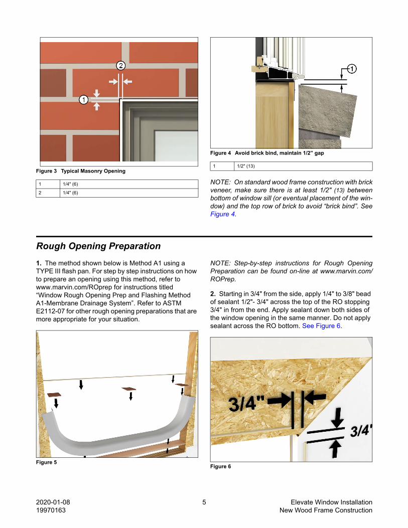
2. Starting in 3/4" from the side, apply 1/4" to 3/8" bead of sealant 1/2"- 3/4" across the top of the RO stopping 3/4" in from the end. Apply sealant down both sides of the window opening in the same manner. Do not apply sealant across the RO bottom. See Figure 6.
Figure 6
1 1/4" (6)
2 1/4" (6)
1 1/2" (13)

2020-01-08 6 Elevate Window Installation19970163 New Wood Frame Construction
3. Place a bead of sealant 1/4"- 3/8" from interior edge of the RO sill. Figure 7
Figure 7
Preparing the Unit for Installation
1. Remove the protective packaging from the unit and dispose/recycle properly. Inspect unit for any hidden damage and report immediately to your Marvin representative. Provide the customer service number etched on one of the top corners of the glass. See Figure 8.
Figure 8
2. On casement and awning units, you may want to apply a filler board to the frame. This will allow for easier shimming during installation. See Figure 9.
Figure 9
3. Position the factory applied nailing fin/drip cap in the upright position. DO NOT APPLY NAILING FIN CORNER GASKETS AT THIS TIME.
4. If you are installing a unit that includes structural brackets, clips and/or additional fasteners, fasten them to unit now following supplemental instructions included. Additional fasteners are required for certain size ELCAP units. Brackets and instructions are sent with those units. Certified mull installations with structural brackets are also covered in these instructions.
1 Sealant
1 Filler board
2 Screw <= 1 1/4" (32)

2020-01-08 7 Elevate Window Installation19970163 New Wood Frame Construction
5. On all units factory or field mulled, mullion joints must be sealed prior to installation. Apply silicone sealant at mullions from the frame exterior edge to the drip cap/nailing fin kerf and across the kerf over the recessed mulling pin as shown in Figure 10.
Figure 10
6. When installing factory mulled units in a two wide two high configuration, apply structural brackets on both sides of all mullion joints. See Figure 11. Follow installation instructions supplied with brackets for specific placement.
Figure 11
7. For certified mull with nail fin installation, see the Certified Mull Anchoring instructions that are included in the certified mull installation kit for further anchoring instructions.
8. Install jamb extension before installing the window in the rough or masonry opening. Follow instructions provided with the jamb extension.
I M P O R TA N T
Unlocked windows can open during installation causingdamage to the window unit or personal injury. Keepingthe unit locked will assist in keeping the unit square untilfastened into the opening.

2020-01-08 8 Elevate Window Installation19970163 New Wood Frame Construction
Installing the Window
S e e k A s s i s t a n c e
Some large windows and/or assemblies are very heavy.Avoid injury by getting help to lift and position the win-dow into the rough opening.
9. Center the window in the opening. Level at the sill and plumb the frame (interior/exterior). Shim under the jambs to bring to level if necessary. See Figure 12.
Figure 12
10. Once level, tack the jamb nailing fin with 2" (51) roofing nails within in 4" (102) from the head jamb (or fasten top brackets if applicable, follow instructions sent with brackets). If fastening through the exterior casing, use 16d casing nails.See Figure 13.
Figure 13
CAUT IONProper shimming is extremely important. Under-shim-ming or over-shimming will result in bowed jambs and orhead jamb. Both conditions can contribute to improperwindow operation

2020-01-08 9 Elevate Window Installation19970163 New Wood Frame Construction
11. From the interior, shim about 4″ (102) from the bottom to square the unit in the opening. Take diagonal measurements of the window. When equal, the window is square in the opening. Adjust the shims until the unit is square in the opening. Figure 14.
Figure 14
12. Once square fasten the lower corners of the nailing fin and recheck for square. See Figure 15.
Figure 15
AT T E N T I O N
For units installed with masonry clips or installationbrackets. Bend bracket around framing member and at-tach with the #8 x 1 5/8″ screws. Angle screws approxi-mately 15° away from the window. Always shim aboveor below brackets. See Figure 16.
NOTE: Depending on construction method or wall type,you may need to modify the clip/bracket to fit the open-ing. Fastening holes should be no more than 1/4" fromthe bend in the bracket. If necessary, drill two 5/32" (3)holes in the bracket.
Figure 16

2020-01-08 10 Elevate Window Installation19970163 New Wood Frame Construction
13. Recheck the diagonals one more time to make sure the unit is square in the opening. If square install additional shims at 15" intervals on center and at each lock point. Always shim at check rails and meeting stiles. See Figure 17.
Figure 17
14. On round tops and other non-rectangular shapes, make sure to shim at bracing locations. See Figure 18.
Figure 18
15. Measure at head jamb, center of unit, and sill to make sure all dimensions are equal. If they are not, you will have to adjust the shims accordingly. See Figure 19.
Figure 19

2020-01-08 11 Elevate Window Installation19970163 New Wood Frame Construction
16. Once the unit is square and plumb in the opening, operate the sash (on operable units) to make sure it is operating properly. If not, you may have to make some adjustments to the shims.
T i p
On operating units, one way to make sure that the unitis installed square is to check the reveal (gap) betweenthe operating sash and the frame. An even revealaround the entire sash generally means a squarely in-stalled unit and will ensure smooth operation.
17. Complete fastening of the nailing fin around the perimeter of the unit with 2" (51) roofing nails 4" (102) from each corner and spaced every 6"- 8" (152-203) on center (or fasten remaining structural brackets).
CAUT IONIf building codes require foam type insulation to form aninfiltration seal, use only low expansion type foam incombination with fiberglass insulation. Foam and foamapplication must conform to ASTM E2112. Follow all in-structions and warnings from the foam manufacturer.
18. Apply nail fin corner gasket to each corner. Follow instructions on the back of the gasket.
For Picture units: See Elevate Double Hung PictureSupplemental Installation Instructions - JambScrews(19970063). Make sure there is a shim directlyabove or below the installation holes.
Flashing the Installation - Air Barrier Applications
1. Flash the installation in a weather board fashion. For step by step instructions refer to marvin.com/ROprep for instructions titled “Window Rough Opening Prep and Flashing Method A1-Membrane Drainage System”. Figure 20 shows the finished result.
Figure 20

2020-01-08 12 Elevate Window Installation19970163 New Wood Frame Construction
Insulating and Sealing the Installation
1. We recommend two possible ways of insulating the RO cavity. Both follow the principle that stopping air intrusion will aid in managing water intrusion into the RO. The first method uses a combination of one bead of low expansion/low compression/closed cell foam at the exterior plane of the RO in conjunction with loose fill fiberglass insulation. The second method uses two beads of low expansion foam (one at the exterior plane of the RO and another at the interior plane of the RO). See Figure 21.
Figure 21 Apply low expansion foam between frame and roughopening.
Final Installation Procedures
1. For ALL applications: Once the exterior finish such as siding or brick veneer is installed, apply bead of sealant between the finish and the frame exterior or casing along the sides. Apply additional beads approximately 1"- 2" (25-51) at the ends on top of the drip cap. Use a backer rod when necessary. See Figure 22 and Figure 23.
Figure 22
1 Sealant
2 Backer rod
3 Low expansion foam
4 Insulation

2020-01-08 13 Elevate Window Installation19970163 New Wood Frame Construction
Figure 23 Apply sealant between window and exterior finish.
Loose Fill Fiberglass Insulation. Insulate the ROcavity with loose fill fiberglass insulation. Install a backerrod and sealant at the interior plane of the RO to createa continuous air seal.See Figure 24.
Figure 24
CAUT IONPerimeter sealant must be Grade NS Class 25 perASTM C920 and compatible with the window productand the finished exterior(s) of the building. Using im-proper sealant could result in sealant failure casing airand water infiltration.
2. Install mullion trim after interior trim or casing is applied.
1 Loose fill fiberglass insulation
2 Backer rod
3 Continuous air seal (sealant)
4 Flashing
5 Sealant underneath drip
6 Backer rod

2020-01-08 14 Elevate Window Installation19970163 New Wood Frame Construction
Final Installation Procedures
1. Interior and mullion trim: Install mullion trim after interior trim or casing is applied.
On Double Hung raise the bottom sash and tilt in. Re-move the red tabbed vinyl shipping blocks from eachside. See Figure 25.
Figure 25
Sash must be raised at least 1" (25) before tilting. Tiltlatches will not work unless sash is raised.
On Casement units, open the sash and remove theshipping blocks (2 or 4) located on the exterior lock-side. See Figure 26.
Figure 26
ELCA units less than 39" (991) in height will have 2 ship-ping blocks in sill/lock-side jamb corner. Units of 39"(991) heights and greater will have 2 additional shippingblocks in the head/lock-side jamb corner (total of 4 ship-ping blocks).

2020-01-08 15 Elevate Window Installation19970163 New Wood Frame Construction
Technical Installation SpecificationsThe following details are specified for proper instal-lation and for the unit to meet the advertised designpressure (DP) rating.
• Rough Opening Width: 1/4" - 1" (6-25) wider than window/door frame outside measurement.
• Rough Opening Height: 1/4" - 1/2" (6-13) higher than window/door frame outside measurement.
• Masonry Opening Width: 1/4 - 1/2" (6-13) wider than window/door frame outside measurement.
• Masonry Opening Height: 1/8" - 1/4" (3-6) higher than window/door frame outside measurement.
AT T E N T I O N
Architectural Detail Manual Specifications:
Rough Opening: Width 1" (25); Height 1/2" (13).
Masonry Opening: Width 1/2" (13); Height 1/4" (6).
• The panning must drain water to the exterior of the cladding OR the exterior surface of a concealed weather resistive barrier.
CAUT IONBe aware that the use of sill pans and other barriers willdecrease the rough opening height clearance. Adjustopening dimensions accordingly.
• The panning system used in these instructions is one component in a structure’s overall water management system. It should be used in conjunction with an appropriate drainage plane compatible with the exterior cladding.
• Flashing materials must comply with ASTM E2112-01, section 5.13 and be compatible with all materials used in installation including panning systems, air barriers and building papers, sheathing, and the window unit.
• Properly flash and/or seal all windows at the exterior, perimeter.
• Sealants used for installation must be Grade NS Class 25 per ASTM C920 and compatible with the building exterior, window exterior surface, and flashing/water management materials.
• Optional foams used for installation must be low expansion only. Foam and foam application must comply with ASTM E2112-01, SEC 5.9.2
• For units with flat casing install with installation brackets, structural masonry brackets, or jamb screws.
• Shims 4" - 6" (102-152) from each corner on jambs and head jambs. Install additional shims at 15" (381) on center and at all locking points. always shim at the check rails and meeting stiles.
• Do not use chemically treated products for shim material.
• fasteners penetrating chemically treated lumber must be a minimum of 0.90 oz/ft2 zinc hot dipped galvanized or stainless steel type 304 or 316.
• The window frame must not come into direct contact with chemically treated wood products.
I M P O R TA N T
Flashing material must not contain asphalt and must becompatible with flexible PVC (vinyl) such as that foundin Marvin vinyl nailing fin.