
Elementary Information on Gears
40
Elementary Information on Gears The Role Gears are Playing Gears are some of the most important elements used in machinery. There are few mechanical devices that do not have the need to transmit power and motion between rotating shafts. Gears not only do this most satisfactorily, but can do so with uniform motion and reliability. In addition, they span the entire range of applications from large to small. To summarize: 1. Gears offer positive transmission of power. 2. Gears range in size from small miniature instrument installations, that measure in only several millimeters in diameter, to huge powerful gears in turbine drives that are several meters in ameter. 3. Gears can provide position transmission with very high angular or linear accuracy, such as used in servomechanisms and precision instruments. 4. Gears can couple power and motion between shafts whose axes are parallel, intersecting or skew. 5. Gear designs are standardized in accordance with size and shape which provides for widespread interchangeability. This introduction is written as an aid for the designer who is a beginner or only superficially knowledgeable about gearing. It provides fundamental, theoretical and practical information. When you select KHK products for your applications please utilize it along with KHK3009 catalog.
Transcript of Elementary Information on Gears

Elementary
Information on
Gears
The Role Gears are PlayingGears are some of the most important elements used in machinery. There are few mechanical devices that do not have the need to transmit power and motion between rotating shafts. Gears not only do this most satisfactorily, but can do so with uniform motion and reliability. In addition, they span the entire range of applications from large to small. To summarize:
1. Gears offer positive transmission of power. 2. Gears range in size from small miniature instrument installations, that measure in only several millimeters in diameter, to huge powerful gears in turbine drives that are several meters in ameter. 3. Gears can provide position transmission with very high angular or linear accuracy, such as used in servomechanisms and precision instruments. 4. Gears can couple power and motion between shafts whose axes are parallel, intersecting or skew. 5. Gear designs are standardized in accordance with size and shape which provides for widespread interchangeability.
This introduction is written as an aid for the designer who is a beginner or only superficially knowledgeable about gearing. It provides fundamental, theoretical and practical information. When you select KHK products for your applications please utilize it along with KHK3009 catalog.

3
4
2
1 33577899
101111121213131821283436
2
Table of Contents
Gear Types and Terminology..........................1.1 Type of Gears ...................................1.2 Symbols and Terminology......................... Gear Trains.........................................................2.1 Single - Stage Gear Train..............................2.2 Double - Stage Gear Train............................ Involute Gearing...........................................3.1 Module Sizes and Standards....................3.2 The Involute Curve....................................3.3 Meshing of Involute Gearing.................3.4 The Generating of a Spur Gear................3.5 Undercutting.............................................3.6 Profile Shifting........................................... Calculation of Gear Dimensions..........4.1 Spur Gears...................................................4.2 Internal Gears...........................................4.3 Helical Gears............................................4.4 Bevel Gears..............................................4.5 Screw Gears.............................................4.6 Cylindrical Worm Gear Pair.......................

Elementary Information on Gears
1.1 Type of gears
In accordance with the orientation of axes, there are three categories of gears:
1. Parallel axes gears2. Intersecting axes gears3. Nonparallel and nonintersecting axes gears
Spur and helical gears are the parallel axes gears. Bevel gears are the intersecting axes gears. Screw or crossed helical gears and worm gears handle the third category. Table 1.1 Lists the gear types per axes orientation.
Also, included in table 1.1 Is the theoretical efficiency range of the various gear types. These figures do not include bearing and lubricant losses. Also, they assume ideal mounting in regard to axis orientation and center distance. Inclusion of these realistic considerations will downgrade the efficiency numbers.
Categories of gears
Intersecting axes
gears
3
(b) Spur Rack
This is a linear shaped gear which can mesh with a spur gear with any number of teeth. The spur rack is a portion of a spur gear with an infinite radius.
(c) Internal Gear
This is a cylindrical shaped gear but with the teeth inside the circular ring. It can mesh with a spur gear. Internal gears are often used in planetary gear systems and also in gear couplings.
(d) Helical Gear
This is a cylindrical shaped gear with helicoid teeth. Helical gears can bear more load than spur gears, and work more quietly. They are widely used in industry. A negative is the axial thrust force the helix form causes.
(e) Helical Rack
This is a linear shaped gear which meshes with a helical gear. Again, it can be regarded as a portion of a helical gear with infinite radius.
(f) Double Helical Gear
This is a gear with both left-hand and right-hand helical teeth. The double helical form balances the inherent thrust forces.
1 Gear Types and Terminology
Parallel axes
gears
Nonparallel andnonintersecting
axes gears
Types of gearsSpur gearSpur rackInternal gearHelical gearHelical rackDouble helical gearStraight bevel gearSpiral bevel gearZerol bevel gearWorm gearScrew gear
Efficiency(%)
98.0 ~ 99.5
98.0 ~ 99.0
30.0 ~ 90.070.0 ~ 95.0
Fig.1.2 Spur rack
Fig.1.3 Internal gear and spur gear
Fig.1.4 Helical gear
Fig.1.5 Helical rack
(1) Parallel Axes Gears
(a) Spur Gear
This is a cylindrical shaped gear in which the teeth are parallel to the axis. It has the largest applications and, also, it is the easiest to manufacture.
Fig.1.1 Spur gearFig.1.6 Double helical gear
Table 1.1 Types of gears and their categories

Elementary Information on Gears
(b) Screw Gear (Crossed Helical Gear)
A pair of cylindrical gears used to drive non-parallel and non-intersecting shafts where the teeth of one or both members of the pair are of screw form.Screw gears are used in the combination of screw gear / screw gear, or screw gear / spur gear.Screw gears assure smooth, quiet operation. However, they are not suitable for transmission of high horsepower.
(4) Other Special Gears
(a) Face Gear
This is a pseudobevel gear that is limited to 90O intersecting axes. The face gear is a circular disc with a ring of teeth cut in its side face; hence the name face gear
(b) Enveloping Worm Gear Pair
This worm gear pair uses a special worm shape in that it partially envelops the worm wheel as viewed in the direction of the worm wheel axis. Its big advantage over the standard worm is much higher load capacity. However, the worm wheel is very complicated to design and produce.
(c) Hypoid Gear
This is a deviation from a bevel gear that originated as a special development for the automobile industry. This permitted the drive to the rear axle to be nonintersecting, and thus allowed the auto body to be lowered. It looks very much like the spiral bevel gear. However, it is complicated to design and is the most difficult to produce on a bevel gear generator.
(2) Intersecting Axes Gears
(a) Straight Bevel Gear
This is a gear in which the teeth have tapered conical elements that have the same direction as the pitch cone base line (generatrix). The straight bevel gear is both the simplest to produce and the most widely applied in the bevel gear family.
(b) Spiral Bevel Gear
This is a bevel gear with a helical angle of spiral teeth. It is much more complex to manufacture, but offers a higher strength and lower noise.
(c) Zerol Bevel Gear
Zerol bevel gear is a special case of spiral bevel gear. It is a spiral bevel with a spiral angle of zero. It has the characteristics of both the straight and spiral bevel gears. The forces acting upon the tooth are the same as for a straight bevel gear.
(3) Nonparallell and Nonintersecting Axes Gears
(a) Worm Gear Pair
Worm gear pair is the name for a meshed worm and worm wheel. The outstanding feature is that it offers a very large gear ratio in a single mesh. It also provides quiet and smooth action. However, transmission efficiency is very poor.
4
Fig.1.7 Straight bevel gear
Fig.1.8 Spiral bevel gear
Fig.1.9 Zerol bevel gear
Fig.1.11 Screw gear
Fig.1.12 Face gear
Fig.1.13 Enveloping worm gear pair
Fig.1.14 Hypoid gear
Fig.1.10 Worm gear pair

Elementary Information on Gears
Terms
Terms
Terms
Angular speedTangential speedRotational speedProfile shift coefficientNormal profile shift coefficientTransverse profile shift coefficientCenter distance modification coefficient
5
1.2 Symbols and Terminology
Table 1.2 through 1.6 indicate the symbols and the terminology used in this catalog. JIS B 0121:1999 and JIS B0102:1999 cancel and replace former JIS B0121 (symbols) and JIS B0102 (vocabulary) respectively. This revision has been made to conform to International Standard Organization (ISO) Standard.
Table 1.2 Linear dimensions and circular dimensions
Table 1.3 Angular dimensions
Table 1.4 Size numbers, ratios & speed terms
Centre distanceReference pitchTransverse pitchNormal pitchAxial pitchBase pitchTransverse base pitchNormal base pitch
Reference pressure angleWorking pressure angleCutter pressure angleTransverse pressure angleNormal pressure angleAxial pressure angleTransverse working pressure angleTip pressure angleNormal working pressure angle
Number of teethEquivalent number of teethNumber of threads, or number of teeth in pinionGear ratioTransmission ratioModuleTransverse moduleNormal moduleAxial moduleDiametral pitchTransverse contact ratioOverlap ratioTotal contact ratio
Reference cylinder helix anglePitch cylinder helix angleMean spiral angleTip cylinder helix angleBase cylinder helix angleReference cylinder lead anglePitch cylinder lead angleTip cylinder lead angleBase cylinder lead angleShaft angleReference cone anglePitch angleTip angleRoot angleAddendum angleDedendum angleTransverse angle of transmissionOverlap angleTotal angle of transmissionTooth thickness half angleTip tooth thickness half angleSpacewidth half angleAngular pitch of crown gearInvolute function
Tooth depthAddendumDedendumChordal heightConstant chord heightWorking depthTooth thicknessNormal tooth thicknessTransverse tooth thicknessCrest widthBase thicknessChordal tooth thicknessConstant chordSpan measurement over k teeth Tooth space Tip and root clearanceCircumferential backlashNormal backlashRadial backlashAngular backlashFacewidthEffective facewidthLeadLength of path of contactLength of approach pathLength of recess pathOverlap lengthReference diameterPitch diameterTip diameterBase diameterRoot diameterCenter reference diameterInner tip diameterReference radiusPitch radiusTip radiusBase radiusRoot radiusRadius of curvature of tooth profileCone distanceBack cone distance
Symbols
a p pt
pn
px
pb
pbt
pbn
α α ' α o
α t
α n
α x
α 't
α a
α 'n
z zv
z1
u i m mt
mn
mx
P εα
εβ
εγ
ω v n x xn
xt
y
β β ' βm
β a
β b
γ γ' γa
γb
Σ δ δ ' δ a
δ f
θ a
θ f
ζα
ζβ
ζγ
ψ ψ a
η τ invα
h ha
hf
ha
hc
h' s sn
st
sa
sb
s sc
W e c jt
jn
jr
jθ b b' pz
gα
g f
ga
gβ
d d' da
db
df
dm
di
r r' ra
rb
rf
r R Rv
Symbols
Symbols

Elementary Information on Gears
Upper case letters
Terms
Lower case letters Spelling
Table 1.7 indicates the Greek alphabet, the internatioal phonetic alphabet.
6
Table 1.5 Others
Table 1.7 The Greek alphabet
Table 1.6 Accuracy/Error terms
Tangential forceAxial forceRadial forcePin diameterIdeal pin diameterMeasurement over rollers (pin)Pressure angle at pin centerCoefficient of frictionCircular thickness factor
Symbols
Ft
Fx
Fr
dp
d'p
M φ μ Κ
ΑΒΓΔΕΖΗΘΙΚΛΜΝΞΟΠΡΣΤΥΦΧΨΩ
αβγδεζηθικλμνξοπrστυφχψω
AlphaBetaGammaDeltaEpsilonZetaEtaThetalotaKappaLambdaMuNuXiOmicronPiRhoSigmaTauUpsilonPhiChiPsiOmega
Terms
Single pitch deviationPitch deviationTotal cumulative pitch deviationTotal profile deviationRunoutTotal helix deviation
Symbols
fpt
fv or fpu
Fp
Fa
Fr
Fb
A numerical subscript is used to distinguish "pinion" from "gear" (Example: z1, z2), "worm" from "worm wheel", "drive gear" from "driven gear", and so forth.

Elementary Information on Gears
7
The transmission ratio is then:
Transmission ratio = = (2.1)
Gear trains can be classified into three types:Transmission ratio < 1 , increasing : n1 < n2
Transmission ratio = 1 , equal speeds: n1 = n2
Transmission ratio > 1 , reducing : n1 > n2
Figure 2.1 illustrates four basic forms. For the very common cases of spur and bevel gear meshes, Figures 2.1(A) and (B), the direction of rotation of driver and driven gears are reversed. In the case of an internal gear mesh, Figure 2.1(C), both gears have the same direction of rotation. In the case of a worm mesh, Figure 2.1(D), the rotation direction of z2 is determined by its helix hand.
The objective of gears is to provide a desired motion, either rotation or linear. This is accomplished through either a simple gear pair or a more involved and complex system of several gear meshes. Also, related to this is the desired speed, direction of rotation and the shaft arrangement.
2.1 Single-Stage Gear Train
A meshed gear is the basic form of a single-stage gear train. It consists of z1 and z2 numbers of teeth on the driver and driven gears, and their respective rotations, n1 & n2.
2 Gear Trains
(A) A Pair of spur gears (B) Bevel gears
(C) Spur gear and internal gear
(D) Worm gear pair
Fig. 2.1 Single-stage gear trains
Gear 2 Gear 1 Gear 2 Gear 1
Gear 2 Gear 1 Right-hand worm gear Left-hand worm gear
Right-hand worm wheel Left-hand worm wheel
z1
z2
n2
n1
(z2 ,n2) (z1 ,n1) (z2 ,n2) (z1 ,n1)
(z2 ,n2) (z1 ,n1) (z1 ,n1) (z1 ,n1)
(z2 ,n2) (z2 ,n2)
Elementary Information on Gears
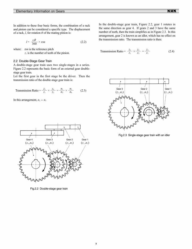
In the double-stage gear train, Figure 2.2, gear 1 rotates in the same direction as gear 4. If gears 2 and 3 have the same number of teeth, then the train simplifies as in Figure 2.3. In this arrangement, gear 2 is known as an idler, which has no effect on the transmission ratio. The transmission ratio is then:
Transmission Ratio = × = (2.4)
In addition to these four basic forms, the combination of a rack and pinion can be considered a specific type. The displacement of a rack, l, for rotation θ of the mating pinion is:
l = × πm (2.2)
where: πm is the reference pitch z1 is the number of teeth of the pinion.
2.2 Double-Stage Gear TrainA double-stage gear train uses two single-stages in a series. Figure 2.2 represents the basic form of an external gear double-stage gear train.Let the first gear in the first stage be the driver. Then the transmission ratio of the double-stage gear train is:
Transmission Ratio = × = × (2.3)
In this arrangement, n2 = n3
8
Gear 4 Gear 3 Gear 2 Gear 1
Fig.2.2 Double-stage gear train
Gear 3 Gear 2 Gear 1
Fig.2.3 Single-stage gear train with an idler
z1
z2
z3
z4
n2
n1
n4
n3
360z1θ
z1
z2
z2
z3
z1
z3
(z4 ,n4) (z3 ,n3) (z2 ,n2) (z1 ,n1)
(z3 ,n3) (z2 ,n2) (z1 ,n1)

Elementary Information on Gears
The invoute profile is the one most commonly used today for gear-tooth forms that are used to transmit power. The beauty of involute gearing is its ease of manufacture and its smooth meshing despite the misalignment of center distance in some degree.
3.1 Module Sizes and StandardsModule m represents the size of involute gear tooth. The unit of module is mm. Module is converted to pitch p , by the factor π . p =πm (3.1)
Table 3.1 is extracted from JIS B 1701-1973 which defines the tooth profile and dimensions of involute gears. It divides the standard module into three series. Figure 3.1 shows the comparative size of various rack teeth.
Table 3.1 Standard values of module unit: mm
NOTE: The preferred choices are in the series order beginning with 1.
Diametral Pitch P(D.P.), the unit to denote the size of the gear-tooth, is used in the USA, the UK, etc. The transformation from Diametral Pitch P(D.P.) to module m is accomplished by the following equation: m = 25.4 / P
Series 1
0.100.100.200.100.300.100.400.100.500.100.600.650.100.100.800.101.001.251.500.102.000.102.500.103.
9
3 Involute Gearing
Series 2
0.10.150.20.250.30.350.40.450.50.550.650.650.700.750.80.90
11.251.51.75
22.252.52.753.250.1
Series 3
00.10
0.10
0.10
0.10
0.10.60.650.10.10
0.1.000.10
0.1.000.10
0.10.13.25
Series 1
4
5
6
8
10
12
16
20
25
32
40
50
Series 2
23.5.6.6
24.5
25.5
27.6
29.6
11.6
14.6
18.6
22.6
28.6.6
36.6
45.6
Series 3
3.75
6.50
Fig.3.1 Comparative size of various rack teeth
M1
M1.5
M2
M2.5
M3
M4
M5
M6
M10

Elementary Information on Gears
3.2 The Involute CurveFigure 3.3 shows an element of involute curve. The definition of involute curve is the curve traced by a point on a straight line which rolls without slipping on the circle. The circle is called the base circle of the involutes. We can see, from Figure 3.3, the length of base circle arc ac equals the length of straight line bc.
tanα = = = θ (radian) (3.4)
The θ in Figure 3.3 can be expressed as invα + α , then Formula (3.4) will become:
invα = tanα - α (3.5)
Function of α, or invα, is known as involute function. Involute function is very important in gear design. Involute function values can be obtained from appropriate tables. With the center of the base circle O at the origin of a coordinate system, the involute curve can be expressed by values of x and y as follows:
x = r cos ( invα )
= cos ( invα )
y = r sin ( invα )
= sin ( invα )
where, r = rb / cosα
The drawings of involute tooth-form can be easily created with this equation.
Pitch, p, is also used to represent tooth size when a special desired spacing is wanted, such as to get an integral feed in a mechanism. In this case, a pitch is chosen that is an integer or a special fractional value. This is often the choice in designing position control systems. Most involute gear teeth have the standard whole depth and a standard pressure angle α = 20°. Figure 3.2 shows the tooth profile of a full depth standard rack tooth and mating gear. It has an addendum of ha = 1m and dedendum hf ≥ 1.25m. If tooth depth is shorter than full depth teeth it is called a “stub” tooth; and if deeper than full depth teeth it is a “high” depth tooth.The most widely used stub tooth has an addendum ha = 0.8m and dedendum hf = 1m. Stub teeth have more strength than a full depth gear, but contact ratio is reduced. On the other hand, a high tooth can increase contact ratio.In the standard involute gear, pitch (p) times the number of teeth becomes the length of reference circle:
dπ= πmz (3.2)Reference diameter (d) is then: d = mz (3.3)
10
(3.6)
Fig.3.3 The involute curve
Fig.3.2 The tooth profile and dimension of standard rack
ocbc
rb
rb θ
cosαrb
cosαrb
pp/2
pb
α α
α
db
d
h fh a
h
y
xO
cr
rb
ainvα
α
bαθ
Module mReference pressure angle α = 20°Addendum ha = mDedendum hf 1.25mTooth depth h 2.25mWorking depth h' = 2.00mTip and root clearance c 0.25 mReference pitch p = πmBase pitch pb = p cosαReference diameter d = mzBase diameter db = d cosα

Elementary Information on Gears
11
3.3 Meshing of Involute Gear
Figure 3.4 shows a pair of standard gears meshing together. The contact point of the two involutes, as Figure 3.4 shows, slides along the common tangent of the two base circles as rotation occurs. The common tangent is called the line of contact, or line of action. A pair of gears can only mesh correctly if the pitches and the pressure angle are the same. That the pressure angles must be identical becomes obvious from the following equation for base pitch: pb = πmcosα (3.7)Thus, if the pressure angles are different, the base pitches cannot be identical.The contact length ab shown Figure 3.4 is described as "Length of path of contact.
The contact ratio can be expressed by the following equation:
Transverse Contact ratio εα = (3.8)
It is good practice to maintain a transverse contact ratio of 1.2 or greater. Under no circumstaces should the ratio drop below 1.1. Module m and the pressure angle α are the key items in the meshing of gears.
3.4 The Generating of a Spur GearInvolute gears can be readily generated by rack type cutters. The hob is in effect a rack cutter. Gear generation is also accomplished with gear type cutters using a shaper or planer machine.Figure 3.5 illustrates how an involute gear tooth profile is generated. It shows how the pitch line of a rack cutter rolling on a pitch circle generates a spur gear.Gear shapers with pinion cutters can also be used to generate involute gears. Gear shapers can not only generate external gears but also generate internal gears.
Fig.3.4 The meshing of involute gear
Fig. 3.5 The generating of a standard spur gear
Rack form tool
Length of path of contact ab Base pitch pb
length of pass of Contact
O1
O2
O1
O1
O2
O2
d1
db1
d2
db2
b
a
α
α
α
dbd
O
I
sin2 α
d 2
( α= 20°, z = 10, x = 0 )

Elementary Information on Gears
2zm
No.
3
Formula Example
ψ a . dasaCrest width
+ + (invα - invαa)(radian)
ψa
Tip tooth thickness half angle
2
m = 2 α = 20° z = 16x = + 0.3 d = 32db = 30.07016da = 37.2αa = 36.06616°inv αa = 0.098835inv α = 0.014904ψa = 1.59815° (0.027893 radian)sa = 1.03762
cos -1αaTip pressure angle1
SymbolItem
3.5 Undercutting
Undercutting is the phenomenon that some of tooth dedendum is cut by the edge of a generating tool. In case gears with small number of teeth is generated as is seen in Figure 3.5, undercut occurs when the cutting is made deeper than interfering point I.The condition for no undercutting in a standard spur gear is given by the expression:
m sin 2 α (3.9)
and the minimum number of teeth is:
z = (3.10)
For pressure angle 20 degrees, the minimum number of teeth free of undercutting is 17. However, the gears with 16 teeth or under can be usable if its strength or contact ratio pose any illeffect.
3.6 Profile Shifting
As Figure 3.5 shows, a gear with 20 degrees of pressure angle and 10 teeth will have a huge undercut volume. To prevent undercut, a positive correction must be introduced. A positive correction, as in Figure 3.6, can prevent undercut. Undercutting will get worse if a negative correction is applied. See Figure 3.7.The extra feed of gear cutter (xm) in Figures 3.6 and 3.7 is the amount of shift or correction. And x is the profile shift coefficient.
The condition to prevent undercut in a spur gear is:
m - xm sin 2 α (3.11)
The number of teeth without undercut will be:
z = (3.12)
The profile shift coefficient without undercut is: x = 1 - sin 2 α (3.13)
Profile shift is not merely used to prevent undercut. It can be used to adjust center distance between two gears.If a positive correction is applied, such as to prevent undercut in a pinion, the tooth tip is sharpened.Table 3.2 presents the calculation of top land thickness ( Crest width ).
12
Table 3.2 The calculations of top land thickness ( Crest width )
Fig.3.6 Generating of positive shifted spur gear Fig.3.7 The generating of negative shifted spur gear Fig. 3.8 Top land thickness
( Crest width )
Rack form toolRack form tool
2mz
sin 2 α2
sin 2 α2 (1-x)
2z
da
db
2zπ
z2x tan α
αdb
dO
xm
sin2 α
d 2
( α= 20°, z = 10, x = +0.5 )
xm
α
db
dO
( α= 20°, z = 10, x = - 0.5 )
(α)
(ψ)
αa
(S)
Sa
ψa

Elementary Information on Gears
Module
No.
13
Formula
To calculate the required strength to determine the specifications, the materials to be used, and the degree of accuracy.To calculate the dimensions in order to provide the necessary data for the gear shaping. To calclate the tooth thickness in order to provide the necessary data for cutting and grinding.To calculate the necessary amount of backlash To calculate the forces to be acting on the gear to provide the necessary information useful for selecting the proper shafts and bearings.To consider what kind of lubrication is necessary and appropriate.
Table 4.1 The calculation of standard spur gears
The following should be taken into consideration in due order at the early stage of designing:
4 Calculation of Gear Dimensions
The explanation is given, hereafter, as to items necessary for the design of gears. The calculation of the dimentions comes first. The dimentions are to be calculated in accordance with the fundamental specifications of each type of gears. The processes of turning etc. are to be carried out on the basis of that data.
4.1 Spur Gears
(1) Standard Spur GearFigure 4.1 shows the meshing of standard spur gears. The meshing of standard spur gears means reference circles of two gears contact and roll with each other. The calculation formulas are in Table 4.1.
1
2
3
4
5
6
7
8
9
10
Item
Reference pressure angle
Number of teeth
Center distance
Reference diameter
Base diameter
Addendum
Tooth depth
Tip diameterRoot diameter
m
Symbol
αz
a
ddb
ha
hda
df
zmd cosα1.00m2.25md + 2md - 2.5m
NOTE
Example
Pinion
320˚
2412
54.000
36.00033.82903.00006.75042.00028.500
72.00067.65803.00006.75078.00064.500
Gear
NOTE : The subscripts 1 and 2 of z1 and z2 denote pinion and gear.
Fig.4.1 The meshing of standard spur gears
2( z1 + z2 ) m
( α= 20°, z1 = 12, z2 = 24, x1 = x2 = 0 )
a
df2
O2
α
db2
da2d2
O1 α
df1
da1
db1
d1

Elementary Information on Gears
No.
14
Formula Example
Table 4.2 The calculation of number of teeth
All calculated values in Table 4.1 are based upon given module (m) and number of teeth (z1 and z2). If instead module (m), center distance (a) and speed ratio (i) are given, then the number of teeth , z1 and z2, would be calculated with the formulas as shown in Table 4.2.
1
2
3
4
5
Item
Module
Center distance
Transmission ratio
Sum of No. of teeth
Number of teeth
Symbol
mai
z1 + z2
z
03.00054.000
0.8
36.000
16 20
Note that the number of teeth probably will not be integervalues by calculation with the formulas in Table 4.2. In thatcase, it will be necessary to resort to profile shifting or to employ helical gears to obtain as near transmission ratio as possible.
m2a
i +1i ( z1 + z2 )
i +1z1 + z2

Elementary Information on Gears
No.
15
15
8
Table 4.3 The calculation of profile shifted spur gear (1)
(2) Profile Shifted Spur GearFigure 4.2 shows the meshing of a pair of profile shifted gears. The key items in profile shifted gears are the operating (working) pitch diameters (d') and the working (operating) pressure angle (α'). These values are obtainable from the modified center distance and the following formulas:
d'1 = 2a
d'2 = 2a
α' = cos- 1
In the meshing of profile shifted gears, it is the operating pitch circle that are in contact and roll on each other that portrays gear action.Table 4.3 presents the calculation where the profile shiht coefficient has been set at x1 and x2 at the beginning. This calculation is based on the idea that the amount of the tip and root clearance should be 0.25 m.
1
2
3
4
5
6
7
9
10
11
12
13
14
Item
Module
Reference pressure angle
Profile shift coefficient
Involute function α'
Working pressure angle
Center distance modification coefficient
Center distance
Reference diameter
Base diameter
Working pitch diameter
Addendum
Tooth depth
Tip diameter
Root diameter
Symbol
mαzx
inv α'
α'
y
a
ddb
d'
ha1
ha2
hda
df
Formula
2 tanα + invα
Find from Involute Function Table
- 1
+ y m
z md cosα
(1 + y-x2) m(1 + y- x1) m {2.25 + y - ( x1 + x2 )}md + 2ha
da -2h
Example
Pinion (1)
320˚
24.000012.000000.6000 00.3600
0.034316
26.0886˚
0.83329
56.4999
36.000033.8289
37.6670
4.420
6.37044.840032.1000
72.000067.6579
75.3330
3.700
79.400066.6600
Gear (2)
(4.1)
A standard spur gear is, according to Table 4.3, aprofile shifted gear with 0 coefficient of shift;that is , x1 = x2 = 0.
Fig. 4.2 The meshing of profile shifted gears
z1 + z2
z1
z1 + z2
z2
2adb1 + db2
z1 + z2
x1 + x2
cosα 'db
2
z1 + z2
2z1 + z2
cosα '
cosα
( α= 20°, z1 = 12, z2 = 24, x1 = + 0.6, x2 = + 0.36 )
df2
O2
α'
a
O1
db2
d2
d'2da2
α'
df1
db1
d1
d'1
Number of teeth

Elementary Information on Gears
No.
16
cos -1
-
Formula Example
Table 4.4 The calculation of profile shifted spur gear (2)
Table 4.4 is the inverse formula of items from 4 to 8 of Table 4.3.
2
3
4
5
Item
Center distance
Center distance modification coefficient
Working pressure angle
Sum of profile shift coefficient
Profile shift coefficient
Symbol
a
y
α '
x1 + x2
x
56.4999
00.8333
26.0886˚
00.9600
0.6000 0.3600
There are several theories concerning how to distribute the sum of profile shift coefficient (x1 + x2) into pinion (x1) and gear (x2) separately. BSS (British) and DIN (German) standards are the most often used. In the example above, the 12 tooth pinion was given sufficient correction to prevent undercut, and the residual profile shift was given to the mating gear.
ma
2z1 + z2
z1 + z2
2ycosα
+ 1
2 tanα( z1 + z2 ) (invα '- invα)
1

Elementary Information on Gears
No.
17
5
6
7
8
9
11
12
13
14
10
FormulaExample
Spur gear Rack
Table 4.5 The calculation of dimensions of a profile shifted spur gear and a rack
(3) Rack and Spur GearTable 4.5 presents the method for calculating the mesh of a rack and spur gear. Figure 4.3(1) shows the the meshing of standard gear and a rack. In this meshing, the reference sircle of the gear touches the pitch lin of the rack.Figure 4.3(2) shows a profile shifted spur gear, with positive
1
2
3
4
Item
Module
Reference pressure angle
Number of teeth
Profile shift coefficient
Height of pitch line
Working pressure angle
Mounting distance
Reference diameter
Base diameter
Addendum
Tooth depth
Tip diameter
Root diameter
Working pitch diameter
Symbol
mαzxHα '
a
ddb
ha
hda
df
d'
+ H + xm
zmd cosα
m ( 1 + x )2.25 md + 2ha
da - 2h
320°
12.—
00.600—
20°
51.800
36.000
—33.829
04.80006.750
45.60032.100
36.000
32.000
03.000
—
One rotation of the spur gear will displace the rack l one circumferential length of the gear's reference circle, per the formula: l = πmz (4.2)
correction xm, meshed with a rack. The spur gear has a larger pitch radius than standard, by the amount xm. Also, the pitch line of the rack has shifted outward by the amount xm.
Table 4.5 presents the calculation of a meshed profile shifted spur gear and rack. If the profile shift coefficient x1 is 0, then it is the case of a standard gear meshed with the rack.
The rack displacement, l, is not changed in any way by the profile shifting. Equation (4.2) remains applicable for any amount of profile shift.
cosα'db
2zm
Fig.4.3(1) The meshing of standard spur gear and rack ( α = 20°, z1 = 12, x1 = 0 )
Fig.4.3(2) The meshing of profile shifted spur gear and rack( α = 20°, z1 = 12, x1 = + 0.6 )
ddb
α
a
H2d
ddb
α
a
H2d
xm

Elementary Information on Gears
No.
18
12
4.2 Internal Gears
(1) Internal Gear Calculations
Figure 4.4 presents the mesh of an internal gear and external gear. Of vital importance is the working pitch diameters (d' ) and working pressure angle (α '). They can be derived from center distance (a' ) and Equations (4.3).
d'1 = 2
a
d'2 = 2 a
α ' = cos -1
Table 4.6 shows the calculation steps. It will become a standard gear calculation if x1 = x2 = 0.
5
6
7
8
10
9
13
14
15
11
FormulaExample
External gear Internal gear
Table 4.6 The calculation of a profile shifted internal gear and externl gear (1)
1
2
3
4
Item
Module
Reference pressure angle
Number of teeth
Profile shift coefficient
Involute function α '
Working pressure angle
Center distance modification coefficient
Center distance
Base diameter
Reference diameter
Addendum
Tooth depth
Tip diameter
Root diameter
Working pitch diameter
Symbol
mαzx
invα '
α '
y
a
db
d
ha1
ha2
hda1
da2
df1
df2
d'
2 tanα + invα
Find from involute Function Table
- 1
+ y m
d cosαz m
( 1 + x1 ) m( 1 - x2 ) m2.25 md1 + 2ha1
d2 - 2ha2
da1- 2hda2 + 2h
320°
16 240 + 0.5
00.060401
31.0937°00
00.3894260
13.16830
72.00045.105 67.65848.000
03.000
06.75000
54.000 69.000
40.500
52.673 79.010
01.500
82.500
(4.3)
z2 -z1
z1
z2 -z1
z2
2adb2-db1
cos α'db
2z2-z1
2z2-z1
cosα '
cosα
z2-z1
x2-x1
Fig.4.4 The meshing of internal gear and external gear( α = 20°, z1 = 16, z2= 24, x1 = x2 = + 0.5 )
O2
db2
da2
d2
df 2
O1
α '
α '
a

Elementary Information on Gears
No.
19
(b) Trochoid Interference
This refers to an interference occurring at the addendum of the external gear and the dedendum of the internal gear during recess tooth action. It tends to happen when the difference between the numbers of teeth of the two gears is small. Equation (4.8) presents the condition for avoiding trochoidal interference.
θ 1 + invα '- invα a2 θ 2 (4.8)
Here
θ1 = cos-1 + invα a1-invα '
θ2 = cos-1
where α a1 is the pressure angle of the spur gear tooth tip:
α a1 = cos -1 (4.10)
α a2 = cos -1
In the meshing of an external gear and a standard internal gear α = 20°, trochoid interference is avoided if the difference of the number of teeth, z1 - z2, is larger than 9.
cos -1
-
Formula Example
Table 4.7 The calculation of profile shifted internal gear and external gear (2)
If the center distance (a) is given, x1 and x2 would be obtained from the inverse calculation from item 4 to item 8 of Table 4.6. These inverse formulas are in Table 4.7.
1
2
3
4
5
Item
Center distance
Center distance modification coefficient
Working pressure angle
Difference of profile shift coefficient
Profile shift coefficient
Symbol
a
y
α '
x2- x1
x
13.1683
00.38943
31.0937°
00.5000
0 0.5
Pinion cutters are often used in cutting internal gears and external gears. The actual value of tooth depth and root diameter, after cutting, will be slightly different from the calculation. That is because the cutter has a profile shift coefficient. In order to get a correct tooth profile, the profile shift coefficient of cutter should be taken into consideration.(2) Interference In Internal Gears
Three different types of interference can occur with internal gears: (a) Involute Interference, (b) Trochoid Interference, and (c) Trimming Interference.
(a) Involute InterferenceThis occurs between the dedendum of the external gear and the addendum of the internal gear. It is prevalent when the number of teeth of the external gear is small. Involute interference can
be avoided by the conditions cited below:
1 - (4.4)
where α a2 is the pressure angle at a tip of the internal gear tooth.
α a2 = cos -1 (4.5)
α ' : working pressure angle
α ' = cos -1 (4.6)
Equiation (4.5) is true only if the tip diameter of the internal gear is bigger than the base circle: da2 db2 (4.7)
For a standard internal gear, where α = 20°, Equation (4.7) is valid only if the number of teeth is z2 > 34.
(4.9)
ma
2z2 - z1
z2 - z1
2ycosα
+ 1
2tanα(z2 - z1) (inv α '- inv α)
z2
z1
tanα 'tanα a2
da2
db2
2a
(z2-z1) m cosα
z2
z1
2ara1
ra22-ra1
2-a2
2ara2
a2+ ra22-ra1
2
da1
db1
da2
db2
Elementary Information on Gears
z0
z0
z0
20
z2
z2
z2
(c) Trimming Interference
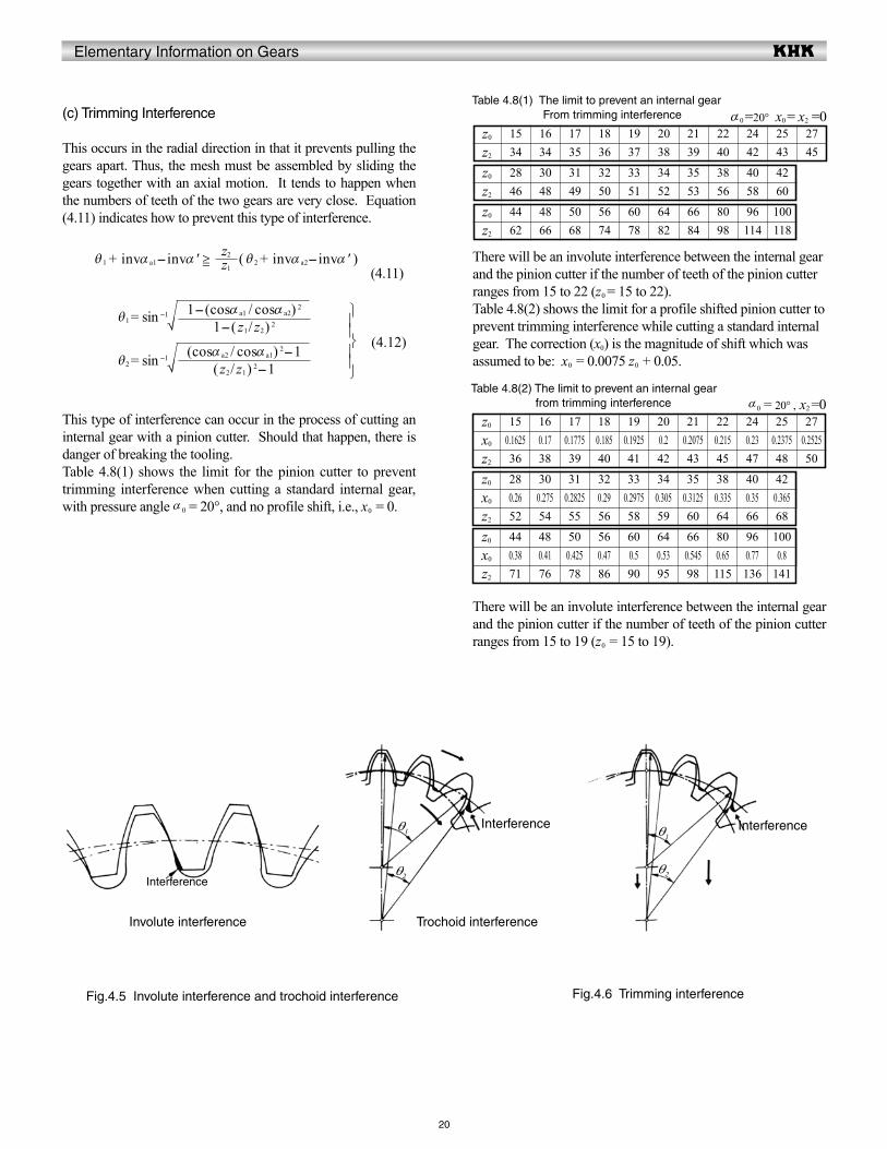
This occurs in the radial direction in that it prevents pulling the gears apart. Thus, the mesh must be assembled by sliding the gears together with an axial motion. It tends to happen when the numbers of teeth of the two gears are very close. Equation (4.11) indicates how to prevent this type of interference.
θ 1 + invα a1-invα ' z1
z2 ( θ 2 + invα a2-invα ' ) (4.11)
θ1 = sin -1
θ2 = sin -1
This type of interference can occur in the process of cutting an internal gear with a pinion cutter. Should that happen, there is danger of breaking the tooling. Table 4.8(1) shows the limit for the pinion cutter to prevent trimming interference when cutting a standard internal gear, with pressure angle α 0 = 20°, and no profile shift, i.e., x0 = 0.
Table 4.8(1) The limit to prevent an internal gear From trimming interference α0 =20° x0 = x2 =0
(4.12)
1534 34 35 36 37 38 39 40 42 43 45
16 17 18 19 20 21 22 24 25 27
4462 66 68 74 78 82 84 98 114 118
48 50 56 60 64 66 80 96 100
2846 48 49 50 51 52 53 56 58 60
30 31 32 33 34 35 38 40 42
There will be an involute interference between the internal gear and the pinion cutter if the number of teeth of the pinion cutter ranges from 15 to 22 (z0
= 15 to 22). Table 4.8(2) shows the limit for a profile shifted pinion cutter to prevent trimming interference while cutting a standard internal gear. The correction (x0) is the magnitude of shift which was assumed to be: x0 = 0.0075 z0 + 0.05.
There will be an involute interference between the internal gear and the pinion cutter if the number of teeth of the pinion cutter ranges from 15 to 19 (z0 = 15 to 19).
Table 4.8(2) The limit to prevent an internal gear from trimming interference α0 = 20° , x2 =0
1-( z1/ z2) 2
1-(cosα a1 / cosα a2) 2
√
( z2/ z1) 2-1(cosα a2 / cosα a1) 2-1
√
Fig.4.5 Involute interference and trochoid interference Fig.4.6 Trimming interference
Involute interference Trochoid interference
Interference
Interference Interferenceθ1
θ2
θ1
θ2
z0
z0
z0
x0
x0
x0
z2
150.162536 38 39 40 41 42 43 45 47 48 50
0.17 0.1775 0.185 0.1925 0.2 0.2075 0.215 0.23 0.2375 0.252516 17 18 19 20 21 22 24 25 27
z2
440.3871 76 78 86 90 95 98 115 136 141
0.41 0.425 0.47 0.5 0.53 0.545 0.65 0.77 0.848 50 56 60 64 66 80 96 100
z2
280.2652 54 55 56 58 59 60 64 66 68
0.275 0.2825 0.29 0.2975 0.305 0.3125 0.335 0.35 0.36530 31 32 33 34 35 38 40 42

Elementary Information on Gears
21
hob if module mn and pressure angle α n are constant, no matter what the value of helix angle β.
It is not that simple in the transverse system. The gear hob design must be altered in accordance with the changing of helix angle β, even when the module mt and the pressure angle α t are the same. Obviously, the manufacturing of helical gears is easier with the normal system than with the transverse system in the plane perpendicular to the axis.
In meshing helical gears, they must have the same helix angle but with opposite hands.
4.3 Helical Gears
A helical gear such as shown in Figure 4.7 is a cylindrical gear in which the teeth flank are helicoid. The helix angle in reference cylinder is β, and the displacement of one rotation is the lead, pz .
The tooth profile of a helical gear is an involute curve from an axial view, or in the plane perpendicular to the axis. The helical gear has two kinds of tooth profiles – one is based on a normal system, the other is based on an transverse system. Pitch measured perpendicular to teeth is called normal pitch, pn. And pn divided by π is then a normal module, mn.
mn = (4.13)
The tooth profile of a helical gear with applied normal module, mn, and normal pressure angle α n belongs to a normal system.
In the axial view, the pitch on the reference is called the transverse pitch, p t. And p t divided by π is the transverse module, mt.
mt = (4.14)
These transverse module mt and transverse pressure angle α t are the basic configuration of transverse system helical gear.In the normal system, helical gears can be cut by the same gear
πpn
πpt
Fig.4.7 Fundamental relationship of a helical gear (Right-hand)
Helix angle
Refe
renc
e di
amet
er
Len
gth
of r
efer
ence
circ
le
Lead
β
px
p tp n
d
πd
pz = πd / tan β

Elementary Information on Gears
22
No.
14
0.023405
tan -1
1
6
5
(1) Normal System Helical GearIn the normal system, the calculation of a profile shifted helical gear, the working pitch diameter d' and transverse working pressure angle α 't is done per Equations (4.15). That is because meshing of the helical gears in the transverse plane is just like spur gears and the calculation is similar.
d'1 = 2a
d'2 = 2a
α 't = cos - 1
Table 4.9 shows the calculation of profile shifted helical gears in the normal system. If normal profile shift coefficients xn1, xn2 are zero, they become standard gears.
(4.15)
13
6
7
8
9
11
10
15
16
17
12
FormulaExample
Pinion Gear
Table 4.9 The calculation of a profile shifted helical gear in the normal system (1)
2
3
4
Item
Normal moduleNormal pressure angle
Reference cylinder helix angle
Number of teeth &helical hand
Normal profile shift coefficient
Transverse pressure angle
Involute function α't
Transverse woking pressure angle
Center distance modification coefficient
Reference diameter
Center distance
Working pitch diameter
Addendum
Tooth depth
Tip diameter
Root diameter
Base diameter
Symbol
mn
αn
βz
xn
α t
inv α't
α't
y
d
a
d'
ha1
ha2
hda
df
db
2 tanα n + invα t
Find from involute Function Table
- 1
+ y mn
( 1+ y-xn2 ) mn
( 1+ y- xn1 ) mn
{2.25 + y- (xn1+xn2 )} mn
d + 2ha
da -2h
d cosα t
320°30°
12(L) 60(R)
+ 0.09809
22.79588°
0
23.1126°
000.09744
41.569 207.846
125.00000
41.667
03.292 002.998
6.74848.15334.657
38.322 191.611
208.333
213.842200.346
z1 + z2
z1
z1 + z2
z2
2adb1 + db2
cosα'tdb
cos βzmn
2cos β
z1 + z2
2cos βz1 + z2
cosα 't
cosα t
z1 + z2
xn1 + xn2
cos β
tanα n

Elementary Information on Gears
23
No.
If center distance, a, is given, the normal profile shift coefficients xn1 and xn2 can be calculated from Table 4.10. These are the inverse equations from items 4 to 10 of Table 4.9.
cos -1
-
Formula Example
Table 4.10 The calculations of a profile shifted helical gear in the normal system (2)
1
2
3
4
5
Item
Center distance
Center distance modification coefficient
Transverse working pressure angle
Sum of profile shift coefficient
Normal profile shift coefficient
Symbol
a
y
α't
xn1 + xn2
xn
125
0.097447
23.1126°
0.09809
0.09809 0
The transformation from a normal system to a transverse system is accomplished by the following equations:
xt = xn cos β
mt =
α t = tan -1
(4.16)
mn
a2cos βz1 + z2
z1 + z2
2y cos βcosα t
+ 1
2tanα n
(z1 + z2) (invα 't - invα t)
cos βmn
cos β
tanα n

Elementary Information on Gears
24
No.
No.
(2) Transverse System Helical Gear
Table 4.11 shows the calculation of profile shifted helical gears in a transverse system. They become standard if xt1 = xt2 = 0.
12
5
6
7
8
10
9
13
14
15
16
11
FormulaExample
Pinion Gear
Table 4.11 The calculation of a profile shifted helical gear in the transverse system (1)
1
2
3
4
Item
Transverse module
Transverse pressure angle
Reference cylinder helix angle
Number of teeth & helical hand
Transverse profile shift coefficient
Involute function α't
Transverse working pressure angle
Center distance modification coefficient
Reference diameter
Center distance
Working pitch diameter
Addendum
Tooth depth
Tip diameter
Root diameter
Base diameter
Symbol
mt
α t
βzxt
invα't
α't
y
d
a
d'
ha1
ha2
hda
df
db
2 tanα t + invα t
Find from Involute Function Table
- 1
zmt
+ y mt
( 1 + y-xt2 ) mt
( 1+ y -xt1 ) mt
{2.25 + y - (xt1 + xt2 )} mt
d + 2ha
da - 2h
d cosα t
320°30°
12 (L) 60 (R)0.34462 0
0.0183886
21.3975°
0.33333
36.0000 180.0000
109.0000
36.3333
04.0000 002.9660
6.71644.000030.5680
33.8289 169.1447
181.6667
185.9320172.5000
cos -1
-
Formula Example
Table 4.12 The calculation of a profile shifted helical gear in the transverse system (2)
1
2
3
4
5
Item
Center distance
Center distance modification coefficient
Transverse working pressure angle
Sum of profile shift coefficient
Transverse profile shift coefficient
Symbol
a
y
α't
xt1 + xt2
xt
109
0.33333
21.39752°
0.34462
0.34462 0
The transformation from a transverse to a normal system is described by the following equations:
xn =
mn = mt cosβ
α n = tan -1 ( tanα t cosβ )
Table 4.12 presents the inverse calculation of items 5 to 9 of Table 4.11.
(4.17)
cosα 't
db
2
z1 + z2
2z1 + z2
cosα 't
cosα t
z1 + z2
xt1 + xt2
mt
a2
z1 + z2
z1 + z2
2ycosα t
+ 1
2tanα t
(z1 + z2) (invα't - invα t)
cosβxt

Elementary Information on Gears
25
No.
(3) Sunderland Double Helical Gear
A representative application of transverse system is a double helical gear, or herringbone gear, made with the Sunderland machine.
The transverse pressure angle, α t, and helix angle, β , are specified as 20° and 22.5°, respectively.
The only differences from the transverse system equations of Table 4.11 are those for addendum and tooth depth. Table4.13 presents equations for a Sunderland gear.
12
5
6
7
8
10
9
13
14
15
16
11
FormulaExample
Pinion Gear
Table 4.13 The calculation of a double helical gear of SUNDERLAND tooth profile
1
2
3
4
Item
Transverse moduleTransverse pressure angle
Reference cylinder helix angle
Number of teeth
Transverse profile shift coefficient
Involute function α'tTransverse working pressure angleCenter distance modification coefficient
Reference diameter
Center distance
Working pitch diameter
Addendum
Tooth depth
Tip diameter
Root diameter
Base diameter
Symbol
mt
α t
βzxt
invα't
α't
y
d
a
d'
ha1
ha2
hda
df
db
2 tanα t + invα t
Find from Involute Function Table
-1
zmt
+ y mt
( 0.8796 + y -xt2 ) mt
( 0.8796 + y - xt1 ) mt
{1.8849 + y - (xt1 + xt2 )}mt
d + 2ha
da - 2h
d cosα t
320°
22.5°12 60
0.34462 0
0.0183886
21.3975°
0.33333
36.0000 180.0000
109.0000
36.3333
03.6390 002.6050
5.62143.278032.0360
33.8289 169.1447
181.6667
185.2100173.9680
cosα 't
db
2
z1 + z2
cosα 't
cosα t
z1 + z2
xt1 + xt2
2z1 + z2

Elementary Information on Gears
26
No.
(4) Helical Rack
Viewed in the transverse plane, the meshing of a helical rack and gear is the same as a spur gear and rack. Table 4.14 presents the calculation examples for a mated helical rack with normal
11
- 27.5
1
5
6
7
8
9
12
13
14
10
FormulaExample
Gear Rack
Table 4.14 The calculation of a helical rack in the normal system
2
3
4
Item
Normal module
Normal pressure angle
Reference cylinder helix angle
Number of teeth & helical hand
Normal profile shift coefficient
Pitch line height
Transverse pressure angle
Mounting distance
Reference diameter
Addendum
Tooth depth
Tip diameter
Root diameter
Base diameter
Symbol
mn
α n
βzxn
H
α t
a
d
ha
hda
df
db
tan -1
+ H + xn mn
mn ( 1 + xn )2.25mn
d + 2ha
da - 2h
d cosα t
2.520°
10° 57' 49"20 (R) - (L)
0 -
20.34160°
52.965
50.92956-
2.5000 2.5005.625
55.9290044.67900
47.75343
-
The formulas of a standard helical rack are similar to those of Table 4.14 with only the normal profile shift coefficient xn = 0. To mesh a helical gear to a helical rack, they must have the same helix angle but with opposite hands.
The displacement of the helical rack, l, for one rotation of the mating gear is the product of the transverse pitch and number of teeth.
l = z (4.18)
According to the equations of Table 4.14, let transverse pitch pt = 8 mm and displacement l = 160 mm. The transverse pitch and the displacement could be modified into integers, if the helix angle were chosen properly.
cosβzmn
cosβ
tanα n
2cosβzmn
cosβπmn
module and normal pressure angle. Similarily, Table 4.15 presents examples for a helical rack in the transverse system (i.e., perpendicular to gear axis).

Elementary Information on Gears
27
No.
11
- 27.5
1
5
6
7
8
9
12
13
10
FormulaExample
Gear Rack
Table 4.15 The calculation of a helical rack in the transverse system
2
3
4
Item
Transverse module
Transverse pressure angle
Reference cylinder helix angle
Number of teeth & helical hand
Transverse profile shift coefficient
Pitch line height
Mounting distance
Reference diameter
Addendum
Tooth depth
Tip diameter
Root diameter
Base diameter
Symbol
mt
α t
βzxt
H
a
d
ha
hda
df
db
+ H + xt mt
zmt
mt ( 1 + xt )2.25mt
d + 2ha
da -2h
d cosα t
2.520°
10° 57′ ' 49"20 (R) - (L)
0 -
52.500
50.00000-
2.5000 2.5005.625
55.0000043.75000
46.98463
-
In the meshing of transverse system helical rack and helical gear, the movement, l, for one turn of the helical gear is the transverse pitch multiplied by the number of teeth. l = πmt z (4.19)
2zmt

Elementary Information on Gears
28
4.4 Bevel GearsBevel gears, whose pitch surfaces are cones, are used to drive intersecting axes. Bevel gears are classified according to their type of the tooth forms into Straight Bevel Gear, Spiral Bevel Gear, Zerol Bevel Gear, Skew Bevel Gear etc.The meshing of bevel gears means pitch cone of two gears contact and roll with each other. Let z1 and z2 be pinion and gear tooth numbers; shaft angle Σ; and reference cone angles δ 1 and δ 2; then:
tan δ 1 =
tan δ 2 =
Generally, shaft angle Σ = 90° is most used. Other angles (Figure 4.8) are sometimes used. Then, it is called “bevel gear in nonright angle drive”. The 90° case is called “bevel gear in right angle drive”.
When Σ = 90°, Equation (4.20) becomes:
δ 1 = tan -1
δ 2 = tan -1
Miter gears are bevel gears with Σ = 90° and z1 = z2. Their transmission ratio z2 / z1 = 1.
Figure 4.9 depicts the meshing of bevel gears. The meshing must be considered in pairs. It is because the reference cone angles δ1 and δ2 are restricted by the gear ratio z1 / z2. In the facial view, which is normal to the contact line of pitch cones, the meshing of bevel gears appears to be similar to the meshing of spur gears.
(4.20)
(4.21)
z2
z1
z1
z2
+ cos Σsin Σ
z1
z2
+ cos Σsin Σ
z2
z1
Fig. 4.8 The reference cone angle of bevel gear
Fig. 4.9 The meshing of bevel gears
z2 m
z1m
Σδ2
δ1
δ2
δ1
R v2
R v1
R
b
d2
d 1

Elementary Information on Gears
29
(1) Gleason Straight Bevel GearsA straight bevel gear is a simple form of bevel gear having straight teeth which, if extended inward, would come together at the intersection of the shaft axes. Straight bevel gears can be grouped into the Gleason type and the standard type.In this section, we discuss the Gleason straight bevel gear. The Gleason Company defined the tooth profile as: tooth depth h = 2.188m; tip and root clearance c = 0.188m; and working depth h' = 2.000m. The characteristics are: • Design specified profile shifted gears:
In the Gleason system, the pinion is positive shifted and the gear is negative shifted. The reason is to distribute the proper strength between the two gears. Miter gears, thus, do not need any shifted tooth profile.
• The tip and root clearance is designed to be parallel:
The face cone of the blank is turnd parallel to the root cone of the mate in order to eliminate possible fillet interference at the small ends of the teeth.
Table 4.16 shows the minimum number of teeth to prevent undercut in the Gleason system at the shaft angle Σ = 90°.
Table 4.16 The minimum numbers of teeth to prevent undercut
Pressure angle
(14.5° ) 29/29 and higher
20°
(25° )
Combination of number of teeth z1 / z2
Table 4.17 presents equations for designing straight bevel gears in the Gleason system. The meanings of the dimensions and angles are shown in Figure 4.10 above. All the equations in Table 4.17 can also be applied to bevel gears with any shaft angle.
The straight bevel gear with crowning in the Gleason system is called a Coniflex gear. It is manufactured by a special Gleason “Coniflex” machine. It can successfully eliminate poor tooth contact due to improper mounting and assembly.
Fig. 4.10 Dimentions and angles of bevel gears
δ a
bR
d i d d a
90° - δ
δ aδδ f
XXb
θ f
θa
ha
hf
h
28/29 and higher16/16 and higher 15/17 and higher 14/20 and higher 13/30 and higher
24/57 and higher25/40 and higher26/35 and higher27/31 and higher
13/13 and higher

Elementary Information on Gears
30
No.
13
12
5
6
7
8
10
9
14
15
16
17
18
11
FormulaExample
Pinion (1) Gear (2)
Tale 4.17 The calcultions of straight bevel gears of the gleason system
1
2
3
4
Item
Shaft angle
Module
Reference pressure angle
Number of teeth
Reference diameter
Reference cone angle
Cone distance
Facewidth
Dedendum
Addendum
Addendum angle
Tip angle
Root angle
Tip diameter
Pitch apex to crown
Axial facewidth
Inner tip diameter
Dedendum angle
Symbol
Σmαzd
δ 1
δ 2
R
b
hf
ha1
ha2
θ a1
θ a2
δa
δ f
da
X
Xb
di
θ f
zm
tan -1
Σ - δ1
It should not exceed R/3 or 10m
2.188m - ha
2.000m - ha2
0.540m +
θ f2
θ f1
δ + θ a
δ - θ f
d + 2ha cosδR cosδ - ha sinδ
da -
tan-1 ( hf / R )
90°3
20°20 04060 120
26.56505° 63.43495°
67.08204
22
02.5290 0 4.599
04.0350 0 1.9650 0
0 3.92194°
30.48699° 65.59398° 24.40602° 59.51301°67.21800c58.19550c
19.00290c
44.84250c
02.15903° 3.92194°
2.15903°
121.7575c028.2425c
009.0969c
081.6609c
The first characteristics of a Gleason Straight Bevel Gear is its profile shifted tooth. From Figure 4.11, we can see the tooth profile of Gleason Straight Bevel Gear and the same of Standard Straight Bevel Gear.
z1 cosδ 2
z2 cosδ 1
0.460m
2 sinδ 2
d2
z1
z2
sinΣ
+ cosΣ
cosθ a
b cosδ a
cosθ a
2b sinδ a
Fig. 4.11 The tooth profile of straight bevel gears
Gleason straight bevel gear Standard straight bevel gear

Elementary Information on Gears
31
No.
(2) Standard Straight Bevel Gears
A bevel gear with no profile shifted tooth is a standard straight bevel gear. The applicable equations are in Table 4.18.
13
12
5
6
7
8
10
9
14
15
16
17
18
11
FormulaExample
Pinion (1) Gear (2)
Table 4.18 Calculation of a standard straight bevel gears
1
2
3
4
Item
Shaft angle
Module
Reference pressure angle
Number of teeth
Reference diameter
Reference cone angle
Cone distance
Facewidth
Dedendum
Addendum
Addendum angle
Tip angle
Root angle
Tip ciameter
Pitch apex to crown
Axial facewidth
Inner tip diameter
Deddendum angle
Symbol
Σmαzd
δ 1
δ 2
R
b
hf
ha
θ a
δ a
δ f
da
X
Xb
di
θ f
zm
tan -1
Σ - δ 1
It should not exceed R/3 or 10m
1.25m1.00m
tan-1 ( ha / R )δ+ θa
δ - θ f
d + 2ha cosδR cosδ - ha sinδ
da -
tan-1 ( hf / R )
90°3
20°20 04060 120
26.56505° 63.43495°
67.08204
22
03.750003.0000
02.56064° 29.12569° 0 65.99559° 23.36545° 0 60.23535°65.36660c58.65840c
19.23740c
43.92920c
03.19960°
122.68330c027.31670c
008.95870c
082.44850c
These equations can also be applied to bevel gear sets with other than 90° shaft angle.
cosθ a
2b sinδ a
cosθ a
b cosδ a
2 sinδ 2
d2
z1
z2
sinΣ
+ cosΣ

Elementary Information on Gears
32
Number of teeth in pinion
(3) Gleason Spiral Bevel Gears
A spiral bevel gear is one with a spiral tooth flank as in Figure 4.12. The spiral is generally consistent with the curve of a cutter with the diameter dc. The spiral angle β is the angle between a generatrix element of the pitch cone and the tooth flank. The spiral angle just at the tooth flank center is called mean spiral angle β m. In practice, spiral angle means mean spiral angle.
All equations in Table 4.21 are dedicated for the manufacturing method of Spread Blade or of Single Side from Gleason. If a gear is not cut per the Gleason system, the equations will be different from these.
The tooth profile of a Gleason spiral bevel gear shown here has the tooth depth h = 1.888m; tip and root clearance c = 0.188m; and working depth h' = 1.700m. These Gleason spiral bevel gears belong to a stub gear system. This is applicable to gears with modules m > 2.1.
Table 4.19 shows the minimum number of teeth to avoid undercut in the Gleason system with shaft angle Σ = 90° and pressure angle α n = 20°.
Table 4.19 The minimum numbers of teeth to prevent undercut β = 35° Pressure angle
17/17 and higher
634 andhigher1.5001.6660.2151.2850.9110.803
──
20°35° ~ 40°
90°
733 andhigher1.5601.7330.2701.2900.9570.8180.757
─
832 andhigher1.6101.7880.3251.2850.9750.8370.7770.777
931 andhigher1.6501.8320.3801.2700.9970.8600.8280.828
1030 andhigher1.6801.8650.4351.2451.0230.8880.8840.883
1129 andhigher1.6951.8820.4901.2051.0530.9480.9460.945
20°
Number of teeth in gear
Working depth
Tooth depth
Gear addendum
Pinion addendum
Tooth thickness of gears2
Spiral angle
Normal pressure angle
Shaft angle
z1
z2
h'h
ha2
ha1
30
40
50
60
α n
βΣ
Combination of numbers of teeth z1 / z2
Table 4.20 Dimentions for pinions with number of teeth less than 12
If the number of teeth is less than 12, Table 4.20 is used to determine the gear sizes.
NOTE: All values in the table are based on m = 1.
Fig.4.12 spiral bevel gear (Left-hand)
δ
Rb
b/2 b/2
Rv
dc
βm
16/18 and higher 13/22 and higher 12/26 and higher14/20 and higher15/19 and higher

Elementary Information on Gears
63.43495°
33
No.
19
Table 4.21 shows the calculations of spiral bevel gears of the Gleason system
15
14
7
8
9
10
12
11
16
17
18
20
13
FormulaExample
Pinion Gear
Table 4.21 The calculations of spiral bevel gears of the Gleason system
1
2
3
4
5
6
Item
Shaft angle
Module
Normal pressure angle
Mean spiral angle
Number of teeth and spiral hand
Transverse pressure angle
Reference diameter
Reference cone angle
Cone distance
Facewidth
Dedendum
Addendum
Addendum angle
Tip angle
Root angle
Tip diameter
Pitch apex to crown
Axial facewidth
Inner tip diameter
Dedendum angle
Symbol
Σmα n
βm
z
α t
d
δ 1
δ 2
R
b
hf
ha1
ha2
θ a1
θ a2
δ a
δ f
da
X
Xb
di
θ f
zm
tan -1
Σ- δ 1
It should be less than 0.3R or 10m
1.888m - ha
1.700m - ha2
0.460m +
θ f2
θ f1
δ + θ a
δ - θ f
d + 2hacosδRcosδ - ha sinδ
da -
tan-1 ( hf / R )
90°3
20° 35°
20 (L)
23.95680
040 (R)
60 120
26.56505°
67.08204
20
02.23650c 003.99150c
03.42750 001.67250
03.40519°
29.97024° 065.34447° 24.65553° 0 60.02976°66.13130c58.46720c
17.35630c
46.11400c
01.90952° 00 3.40519°
0 01.90952°
121.49590c028.50410c
098.34790c
85.1224
All equations in Table 4.21 are also applicable to Gleason bevel gears with any shaft angle. A spiral bevel gear set requires matching of hands; left-hand and right-hand as a pair.
(4) Gleason Zerol Bevel Gears
When the spiral angle βm = 0, the bevel gear is called a Zerol bevel gear. The calculation equations of Table 4.17 for Gleason straight bevel gears are applicable. They also should take care again of the rule of hands; left and right of a pair must be matched.
Figure 4.13 is a left-hand Zerol bevel gear.
z1
z2
sinΣ+ cosΣ
2 sinδ 2
d2
z1 cosδ 2
z2 cosδ 1
0.390m
cosθ a
b cosδ a
cosθ a
2b sinδ a
Fig. 4.13 Left-hand zerol bevel gear
tan -1 ( cosβ
tanα n )

Elementary Information on Gears
34
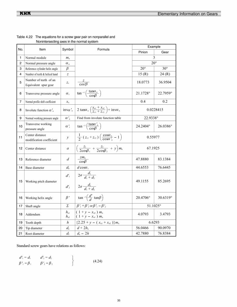
4.5 Screw Gears
Screw gearing includes various types of gears used to drive nonparallel and nonintersecting shafts where the teeth of one or both members of the pair are of screw form. Figure 4.14 shows the meshing of screw gears.Two screw gears can only mesh together under the conditions that normal modules (mn1) and (mn2) and normal pressure angles (an1, an2) are the same.
Let a pair of screw gears have the shaft angle Σ and helix angles β 1 and β 2:
If they have the same hands, then: Σ = β 1 + β 2
If they have the opposite hands, then: Σ = β 1 - β 2 or Σ = β 2 - β 1
(4.22)
If the screw gears were profile shifted, the meshing would become a little more complex. Let β'1, β'2 represent the working pitch cylinder;
If they have the same hands, then: Σ = β '1 + β '2
If they have the opposite hands, then: Σ = β '1 - β '2 or Σ = β '2 - β '1
(4.23)
Table 4.22 presents equations for a profile shifted screw gear pair. When the normal profile shift coefficients xn1 = xn2 = 0, the equations and calculations are the same as for standard gears.
Fig.4.14 Screw gears of nonparallel and nonintersecting axes
Gear 1
Gear 2
(Right-hand) (Left-hand)
(Right-hand)
β 2 β2
β1
β 1Σ
Σ
Elementary Information on Gears
35
No.
19
16
17
18
00.0228415
tan -1
1
7
6
5
15
8
10
9
11
13
12
20
21
14
FormulaExample
Pinion Gear
Table 4.22 The equations for a screw gear pair on nonparallel and Nonintersecting axes in the normal system
2
3
4
Item
Normal module
Normal pressure angle
Reference cylinder helix angle
Number of teeth & helical hand
Normal profile shift coefficient
Transverse pressure angle
Number of teeth of anEquivalent spur gear
Involute function α 'n
Transverse working pressure angle
Normal working pressure angle
Center distance modification coefficient
Reference diameter
Center distance
Working pitch diameter
Working helix angle
Addendum
Tooth depth
Tip diameter
Root diameter
Base diameter
Shaft angle
Symbol
mn
α n
βz
xn
α t
zv
invα 'n
α 't
α 'n
y
d
a
d'1
d'2
β '
ha1
ha2
hda
df
db
Σ
2 tanα n + invα n
tan -1
Find from involute function table
( zv1 + zv2 ) - 1
+ + y mn
2a
2a
tan -1 tanβ
( 1 + y - xn2 ) mn
( 1 + y - xn1 ) mn
{2.25 + y - ( xn1 + xn2 )}mn
d + 2ha
da - 2h
d cosα t
β '1 + β '2 or β '1 - β '2
320°
20° 30°15 (R) 24 (R)
0.4
21.1728° 22.7959°
18.0773 36.9504
0.2
24.2404° 26.0386°
22.9338°000
0.55977c
47.8880c 83.1384c
67.1925c
49.1155c
20.4706°
04.0793c
30.6319°
03.4793c
6.629356.0466c42.7880c
44.6553c
51.1025°
76.6445c
85.2695c
90.0970c76.8384c
Standard screw gears have relations as follows:
d'1 = d1 d'2 = d2
β '1 = β 1 β '2 = β 2
(4.24)
d
d'
d1 + d2
d2
d1 + d2
d1
cosβzmn
2cosβ 1
z1
2cosβ 2
z2
21
cosα 'n
cosα n
cosβ
tanα 'n
zv1 + zv2
xn1 + xn2
cosβ
tanα n
cos3βz

Elementary Information on Gears
36
Worm
mx = mn mt =
α x = tan-1 α n α t = tan-1
px = πmx pn = πmn pt = πmt
pz = πmxz pz = pz = πmtz tanγ
4.6 Cylindrical Worm Gear Pair
Cylindrical worms may be considered cylindrical type gears with screw threads. Generally, the mesh has a 90O shaft angle. The number of threads in the worm is equivalent to the number of teeth in a gear of a screw type gear mesh. Thus, a one-thread worm is equivalent to a one-tooth gear; and two-threads equivalent to two-teeth, etc. Referring to Figure 4.15, for a reference cylinder lead angle γ, measured on the pitch cylinder, each rotation of the worm makes the thread advance one lead pz.
There are four worm tooth profiles in JIS B 1723, as defined on the right.
Type I Worm: The tooth profile is trapezoidal on the axial plane. Type II Worm: The tooth profile is trapezoid on the plane normal to the space.Type III Worm: The tooth profile which is obtained by inclining the axis of the milling or grinding, of which cutter shape is trapezoidal on the cutter axis, by the lead angle to the worm axis. Type IV Worm: The tooth profile is of involute curve on the plane of rotation.
Type III worm is the most popular. In this type, the normal pressure angle α n has the tendency to become smaller than that of the cutter, α 0.Per JIS, Type III worm uses a axial module mx and cutter pressure angle α 0 = 20° as the module and pressure angle. A special worm hob is required to cut a Type III worm wheel.Standard values of axial module, mx , are presented in Table 4.23.
Because the worm mesh couples nonparallel and nonintersecting axes, the axial plane of worm does not correspond with the axial plane of worm wheel. The axial plane of worm corresponds with the trsnsverse plane of worm wheel. The transverse plane of worm corresponds with the axial plane of worm wheel. The common plane of the worm and worm wheel is the normal plane. Using the normal module, mn, is most popular. Then, an ordinary hob can be used to cut the worm wheel.
Table 4.24 presents the relationships among worm and worm wheel axial plane, transverse plane, normal plane, module, pressure angle, pitch and lead.
Table 4.23 Axial module of cylindrical worm gear pair
1
6.30 8.00 10.00 12.50 16.00 20.00 25.00
1.25 1.60 2.00 2.50 3.15 4.00 5.00
Table 4.24 The relations of cross sections of worm gear pair
Worm wheel
Axial plane
Transverse plane
Normal plane
Norml plane
Transverse plane
Axial plane
cosγtanα n
cosγmn
cosγπmn z
sinγmn
sinγ
tanα n
Fig. 4.15 Cylindrical worm (Right-hand)
γ
β
px
α xα n
α t
pn
pn
p t
d
π d
pz =πd tan γ
NOTE: The transverse plane is the plane perpendicular to the axis.

Elementary Information on Gears
37
No.
13
10
2
Reference to Figure 4.15 can help the understanding of the relationships in Table 4.24. They are similar to the relations in Formulas (4.16) and (4.17) that the helix angle β be substituted by (90° – γ). We can consider that a worm with lead angle γ is almost the same as a helical gear with helix angle (90° – γ).
(1) Axial Module Worm Gear Pair
Table 4.25 presents the equations, for dimensions shown in Figure 4.16, for worm gears with axial module, mx, and normal pressure angle α n = 20°.
Table 4.25 The calculations of axial module system worm gear pair
11
─ 0
1
5
6
7
8
9
12
FormulaExample
Worm Wheel
3
4
Item
Axial module
Normal pressure angle
No. of threads, no. of teeth
Reference diameter
Reference cylinder lead angle
Profile shift coefficient
Center distance
Addendum
Tip diameter
Throat diameter
Throat surface radius
Root diameter
Tooth depth
Symbol
mx
α n
zd1
d2
γ
xt2
a
ha1
ha2
da1
da2
dt
ri
df1
df2
h
(Qmx) NOTE 1z2 mx
tan -1
+ xt2 mx
1.00 mx
(1.00 + xt2) mx
d1 + 2ha1
d2 + 2ha2 + mx NOTE 2d2 + 2ha2
- ha1
da1 - 2hdt - 2h
2.25 mx
3(20° )
Double(R) * 30 (R)
44.000 90.000
7.76517°
67.000
3.000 3.000
50.000 99.000
─ 96.000
─
36.500
6.750
19.000
82.500
Fig. 4.16 Dimentions of cylindrical worm gear pair
NOTE 1: Diameter factor, Q, means reference diameter of worm, d1, over axial module, mx.
Q =
NOTE 2: There are several calculation methods of worm wheel tip diameter da2 besides those in Table 4.25.NOTE 3: The facewidth of worm, b1, would be sufficient if: b1 = πmx (4.5+ 0.02z2)NOTE 4: Effective facewidth of worm wheel b' = 2mx√ Q + 1. So the actual facewidth of b2 b' + 1.5 mx would be enough.
mx
d1
d1
mx z1
2d1 + d2
2d1
γ
ri
ad f
1 d 1 d a1
d f2 d 2 d t d a2
* Double-threaded right-hand worm .

Elementary Information on Gears
38
No.
13
14
11
2
(2) Normal Module System Worm Gear Pair
The equations for normal module system worm gears are based on a normal module, mn, and normal pressure angle, α n = 20°. See Table 4.26.
Table 4.26 The calculations of normal module system worm gear pair
12
- - 0.1414
1
6
7
8
9
10
FormulaExample
Worm Worm Wheel
3
4
5
Item
Normal module
Normal pressure angle
No. of threads, No. of teeth
Reference diameter of worm
Reference cylinder lead angle
Reference diameter of worm wheel
Normal profile shift coefficient
Center distance
Addendum
Tip diameter
Throat diameter
Throat surface radius
Root diameter
Tooth depth
Symbol
mn
α n
zd1
γ
d2
xn2
a
ha1
ha2
da1
da2
dt
ri
df1
df2
h
sin -1
+ xn2mn
1.00 mn
(1.00 + xn2) mn
d1 + 2ha1
d2 + 2ha2 + mn
d2 + 2ha2
- ha1
da1 - 2hdt - 2h
2.25 mn
3( 20° )
Double(R) *44.000
30 (R)-
7.83748°
- 90.8486
67.000
3.000 2.5758
50.000 99.000
- 96.000
-
36.500
6.750
19.000
82.500
(3) Crowning of the Tooth
Crowning is critically important to worm gears. Not only can it eliminate abnormal tooth contact due to incorrect assembly, but it also provides for the forming of an oil film, which enhances the lubrication effect of the mesh. This can favorably impact endurance and transmission efficiency of the worm mesh. There are four methods of crowning worm gear pair:
(a) Cut Worm Wheel with a Hob Cutter of Greater Reference
Diameter than the Worm.A crownless worm wheel results when it is made by using a hob that has an identical pitch diameter as that of the worm. This crownless worm wheel is very difficult to assemble correctly. Proper tooth contact and a complete oil film are usually not possible. However, it is relatively easy to obtain a crowned worm wheel
by cutting it with a hob whosereference diameter is slightlylarger than that of the worm.
This is shown in Figure 4.17. This creates teeth contact in the center region with space for oil film formation.
NOTE: All notes are the same as those of Table 4.25.
2d1
2d1 + d2
cosγz2mn
d1
mn z1
Fig.4.17 The method of using a greater diameter hob
Worm
Hob
* Double-threaded right-hand worm .
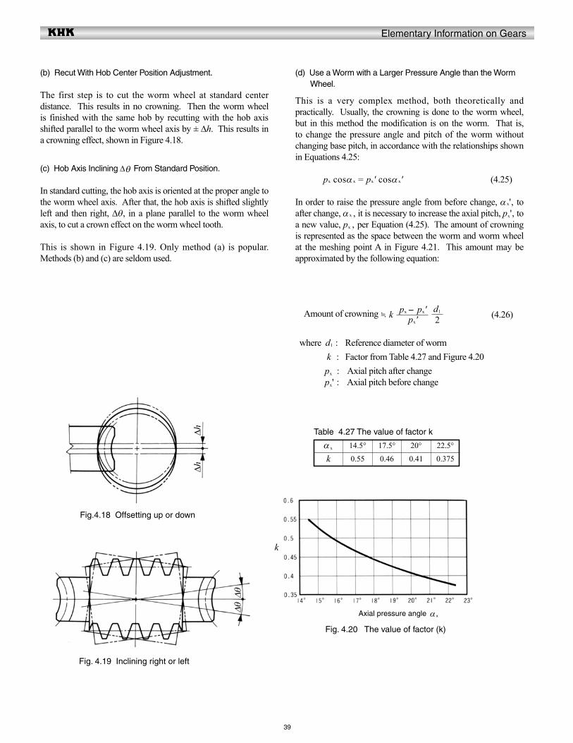
Elementary Information on Gears
39
(d) Use a Worm with a Larger Pressure Angle than the Worm Wheel.
This is a very complex method, both theoretically and practically. Usually, the crowning is done to the worm wheel, but in this method the modification is on the worm. That is, to change the pressure angle and pitch of the worm without changing base pitch, in accordance with the relationships shown in Equations 4.25:
px cosα x = px' cosα x' (4.25)
In order to raise the pressure angle from before change, α x', to after change, α x , it is necessary to increase the axial pitch, px', to a new value, px , per Equation (4.25). The amount of crowning is represented as the space between the worm and worm wheel at the meshing point A in Figure 4.21. This amount may be approximated by the following equation:
Amount of crowning k (4.26)
where d1 : Reference diameter of worm k : Factor from Table 4.27 and Figure 4.20 px : Axial pitch after change px' : Axial pitch before change
(b) Recut With Hob Center Position Adjustment.
The first step is to cut the worm wheel at standard center distance. This results in no crowning. Then the worm wheel is finished with the same hob by recutting with the hob axis shifted parallel to the worm wheel axis by ± Δh. This results in a crowning effect, shown in Figure 4.18.
(c) Hob Axis Inclining Δθ From Standard Position.
In standard cutting, the hob axis is oriented at the proper angle to the worm wheel axis. After that, the hob axis is shifted slightly left and then right, Δθ, in a plane parallel to the worm wheel axis, to cut a crown effect on the worm wheel tooth.
This is shown in Figure 4.19. Only method (a) is popular. Methods (b) and (c) are seldom used.
Table 4.27 The value of factor k
α x 14.5° 17.5° 20° 22.5°
k 0.55 0.46 0.41 0.375
Fig.4.18 Offsetting up or down
Fig. 4.19 Inclining right or left
Fig. 4.20 The value of factor (k)
px'px - px'
2d1
ΔhΔh
ΔθΔθ Axial pressure angle α x
k

Elementary Information on Gears
40
Table 4.28 shows an example of calculating worm crowning.
13
14
15
16
11
After crowning
2
Table 4.28 The calculation of worm crowning
12
1
6
7
8
9
10
Formula ExampleNo.
3
4
5
Item
Axial module
Normal pressure angle
Number of threads of worm
Reference diameter of worm
Reference cylinder lead angle
Axial pressure angle
Axial pitch
Lead
Amount of crowning
Axial pitch
Axial pressure angle
Axial module
Reference cylinder lead angle
Normal pressure angle
Lead
Factor
Symbol
mx'α n'z1
d1
γ '
α x'
px'pz'
CR
px
α x
mx
γ
α n
pz
k
NOTE: These are the data before crowning.
tan -1
tan -1
πmx'πmx z1
*
px' + 1
cos -1 cosα x'
tan -1
tan -1 ( tanα x cosγ )πmx z1
From Table 4.27
320°2
44.000000c
7.765166°
20.170236°
18.849556c09.424778c
00.040000c
09.466573c
20.847973°
03.013304c
7.799179°
20.671494°18.933146c
00.410000c
(4) Self-Locking Of Worm Gear Pair
Self-locking is a unique characteristic of worm meshes that can be put to advantage. It is the feature that a worm cannot be driven by the worm wheel. It is very useful in the design of some equipment, such as lifting, in that the drive can stop at any position without concern that it can slip in reverse. However, in some situations it can be detrimental if the system requires reverse sensitivity, such as a servomechanism.
Self-locking does not occur in all worm meshes, since it requires special conditions as outlined here. In this analysis, only the driving force acting upon the tooth surfaces is considered without any regard to losses due to bearing friction, lubricant agitation, etc. The governing conditions are as follows:
Let Ft1 = tangential driving force of worm
Then, Ft1 = Fn (cosα n sinγ - μcosγ ) (4.27)
If Ft1 > 0 then there is no self-locking effect at all. Therefore, Ft1 ≤ 0 is the critical limit of self-locking.
Let αn in Equation (4.27) be 20°, then the condition: Ft1 ≤ 0 will become: (cos20° sinγ – μcosγ ) ≤ 0
Figure 4.22 shows the critical limit of self-locking for lead angle γ and coefficient of friction μ. Practically, it is very hard to assess the exact value of coefficient of friction μ. Further, the bearing loss, lubricant agitation loss, etc. can add many side effects. Therefore, it is not easy to establish precise self-locking conditions. However, it is true that the smaller the lead angle γ, the more likely the self-locking condition will occur.
d1
mx z1
πpx
px
px'
kd1
2CR
cosγ '
tanα n'
d1
mx'z1
Fig. 4.22 The critical limit of self-locking of lead angle γ and
Fig.4.21 Position A is the point of determining crowning amount
Lead angle γ
μnoitcirf fo tneiciffeo
C
A
d1
30°
* It should be determined by considering the size of tooth contact .