ELECTROSTATICS - Marion County Public Schools 01 - NOTES...ELECTRICITY Rene’ McCormick, AP...
28
ELECTRICITY Rene’ McCormick, AP Strategies, Inc. 1 ELECTROSTATICS I. ELECTRIC CHARGE A. Charges at rest 1. Electrification --process that produces electric charge is confined to the object and not moving L electrostatic charge 2. static electricity --stationary electricity in the form of an electric charge at rest L friction B. Two Kinds of Charge 1. electroscope --detects electrostatic charges a. rubber/fur L repels b. glass/ silk L attracts c. therefore L 2 kinds of charge 2. Basic law of electrostatics--opposites attract and likes repel C. Electricity and Matter 1. p+, e- and n o # p+ = # e- so NO net charge on an atom a. e- mass = 9.1095 x 10 -31 kg p+ mass = 1.6726 x 10 -27 kg n o mass = 1.6750 x 10 -27 kg b. p+ & n o bound in nucleus by strong forces acting through short distances c. repulsion between p+'s are due to weak forces d. e- hang around due to + attraction by nucleus; outer e-'s are held less strongly L especially metallic e-'s e. Two materials in close contact, some loosely held e-'s can be transferred from one material to the other D. Electroscope 1. Vane electroscope--light Al rod mounted by central bearing on a metal support L vane is deflected and the angle depends on charge
Transcript of ELECTROSTATICS - Marion County Public Schools 01 - NOTES...ELECTRICITY Rene’ McCormick, AP...

ELECTRICITYRene’ McCormick, AP Strategies, Inc. 1
ELECTROSTATICSI. ELECTRIC CHARGE
A. Charges at rest1. Electrification--process that produces electric charge is confined to the object and not
moving L electrostatic charge2. static electricity--stationary electricity in the form of an electric charge at rest L
frictionB. Two Kinds of Charge
1. electroscope--detects electrostatic chargesa. rubber/fur L repelsb. glass/ silk L attractsc. therefore L 2 kinds of charge
2. Basic law of electrostatics--opposites attract and likes repel
C. Electricity and Matter1. p+, e- and no # p+ = # e- so NO net charge on an atom
a. e- mass = 9.1095 x 10⁻³¹ kg p+ mass = 1.6726 x 10⁻²⁷ kg no mass =
1.6750 x 10⁻²⁷ kgb. p+ & no bound in nucleus by strong forces acting through short distancesc. repulsion between p+'s are due to weak forcesd. e- hang around due to + attraction by nucleus; outer e-'s are held less strongly
L especially metallic e-'se. Two materials in close contact, some loosely held e-'s can be transferred from
one material to the otherD. Electroscope
1. Vane electroscope--light Al rod mounted by central bearing on a metal support Lvane is deflected and the angle depends on charge

ELECTRICITYRene’ McCormick, AP Strategies, Inc. 2
2. Leaf electroscope--very fragile strips of gold leaf suspended from a metal stem3. proof plane--test or transfer charges. Small metal disk with insulating handle
E. Conductors & Insulators (solids)1. conductor--material that transfers Electric (e-) charge L Ag, Cu, Al2. insulator--material that doesn't transfer e- charge L glass, mica, paraffin, hard rubber,
sulfur, silk, dry air, plastic3. Al--27g = 6.02 x 10²³ atoms w/ 13 e- each = 7.83 x 1024 e- so 1e-/2.2 amu of matter
a. metals have close packed crystal structures: + chargedparticles w/ a cloud of free e-'s L e- in a gas have same charge, repel andspread out. When they contact a charged body, e- surge + ½ e- or -¼ e-
attracted repelled4. Insulators lack free e- ( usually not crystals either)
F. Transferring Electric Charges
1. e- travel from rod & cause leaves to diverge (repel) L induced charge2. once source is removed free e- scatter throughout metal knob etc. restoring e-
equilibrium. Best done in dry air3. moist air L water coats everything and static charge cannot be maintained4. ANY conducting object can be induced! Region of object nearest charged body will
acquire a charge of opposite sign and region farthest from the charged body willacquire a charge of the same sign.
5. Charge transferred by conduction--when leaves stay diverged (acquired charge)--anyconducting object acquires a residual charge of the same sign as that of the bodytouching it.
G. Residual charge by Induction1. A charged rubber rod (-) is held near knob L no transfer of e-. When an isolated
conductor is given a residual charge by induction, the charge is opposite in sign to thatof the object inducing it.

ELECTRICITYRene’ McCormick, AP Strategies, Inc. 3
H. The Force Between Charges
1. point charges--when a uniform charge on the surface of asphere causes the sphere to behave as if the charge wereconcentrated in the middle
2. q--quantity of charge & measured in coulombs (c); 1c =6.25 x 10¹⁸ electrons 1:c = 10-6 c q for an electron= -1.60 x 10⁻¹⁹ c q for a proton = +1.60 x 10⁻¹⁹ c
3. COULOMB'S LAW of electrostatics--The force between 2point charges is directly % to the product of theirmagnitudes and inversely % to the square of the distancebetween them.
Coulomb’s Law: F = k qq' F = 1 qq’ d2 4B,o d2
a. K accounts for properties of medium separating charged bodiesb. K = 9.0 x 10⁹ NCm2/C2 in a vacuum c. ,o = 1/4Bk = 8.85 x 10⁻¹² C2/NCm2 called the permitivity of free space
d. - means repulsion + means attraction
II. ELECTRIC FIELDS--exist in a region of space if an electric charge placed in that region is subjectto an elec. force.
A. Electric line of force--line so drawn that a tan to it at any point indicates the orientation of theelectric field at that point.1. originate at surface of + charged body and terminate at surface of - charged body.
Each line shows direction a + test charge would follow and is normal to the surface of

ELECTRICITYRene’ McCormick, AP Strategies, Inc. 4
the charged body where it joins that surface.2. Intensity--% to the # of lines of force per unit area normal to the field:
E = F = k Q q r2 E L Electric field intensity F L Force in Newtons q L POSITIVE test charge in coulombs
EXAMPLE 1
Find the force between charges of +100.0 :c and -50.0 :c located 50.0 cm apart.
EXAMPLE 2
What force acts on two electrostatic charges of 60.8 :c and 76.5 :c isolated in air 42.5 cm apart?

ELECTRICITYRene’ McCormick, AP Strategies, Inc. 5
EXAMPLE 3
Two small isolated spheres are 20.0 cm apart. The sphere on the left receives a charge of +10.8 :c and thesphere on the right receives a charge of +12.2 :c. What force acts on each charge and in what direction?
EXAMPLE 4 (vector flashback)
Three charged particles are arranged in a line. Calculate the netelectrostatic force on particle 3 due to the other 2 charges.
EXAMPLE 5
Calculate the net electrostatic force on charge Q3 due to the other charges present.
ELECTRICITYRene’ McCormick, AP Strategies, Inc. 6
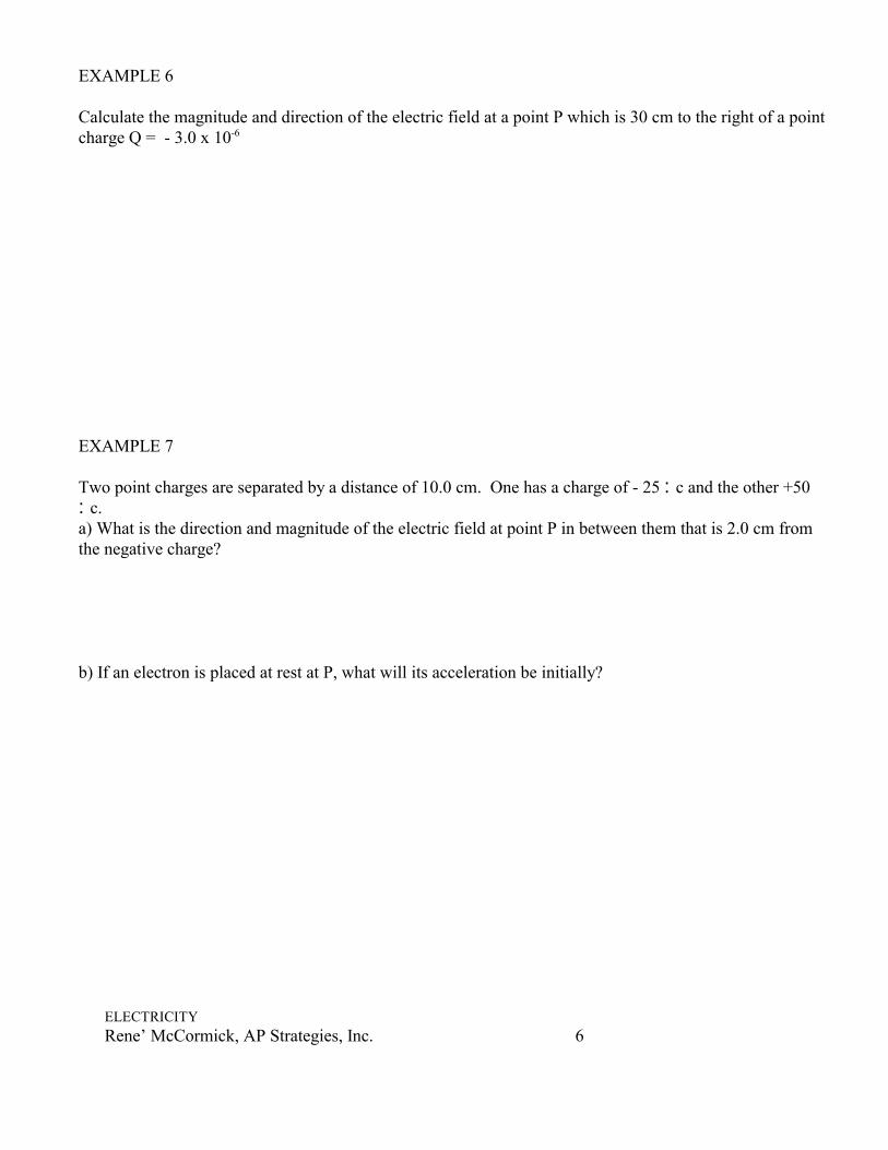
EXAMPLE 6
Calculate the magnitude and direction of the electric field at a point P which is 30 cm to the right of a pointcharge Q = - 3.0 x 10⁻⁶
EXAMPLE 7
Two point charges are separated by a distance of 10.0 cm. One has a charge of - 25 :c and the other +50:c.a) What is the direction and magnitude of the electric field at point P in between them that is 2.0 cm fromthe negative charge?
b) If an electron is placed at rest at P, what will its acceleration be initially?

ELECTRICITYRene’ McCormick, AP Strategies, Inc. 7
EXAMPLE 8
Calculate the total electric field at a point A and point B due to both charges Q1 and Q2

ELECTRICITYRene’ McCormick, AP Strategies, Inc. 8
III. POTENTIAL DIFFERENCEA. Electric Potential
1. A charge in an electric field experiences a force according to Coulomb's lawa. If charge moves in response to force, work is done by elec. field and Energy is
removed from the systemb. If charge is moved against the coulomb force, work is done on it using Energy
from some outside source, Energy is storedc. If work is done as a charge moves from 1 point to another in an electric field,
or if work is required to move a charge from 1 point to another, these 2 pointsdiffer in electric potential.
d. Magnitude of the work is a measure of this difference of potential2. Potential difference, V, between 2 points in an electric field is the work done per unit
charge as a charge is moved between these points: V = work = w = PE charge q q
a. volt--V between 2 points in an electric field such that 1 joule of work is donein moving a charge of 1 coulomb between these points:
1 volt = 1 joule 1 coulomb
b. Say, v = 6.0 and q = 3 x 10² :c V = w/q so W = Vq = 6.0 v x 300:c x 1c/106 :c = .0018j Since j = 1 NA m it follows:
v = j = NA m c c
v = N so m c
E = N = v c m
c. E is often expressed in v/m and is called the potential gradient --Î inpotential/unit distance
d. Earth is a source and a sink for e-'s. E = 0 for Earth. Any conductorconnected to Earth has an E = 0 and is grounded.
B. Distribution of Charges on an isolated object--Michael Faraday He charged a conical silk bag and found that the charge was on the outside of thebag.
Pull on the silk thread and turn the bag inside out and the charge was again on theoutside of the bag.
Either way charge is on the outside of the silk bag.
ELECTRICITYRene’ McCormick, AP Strategies, Inc. 9
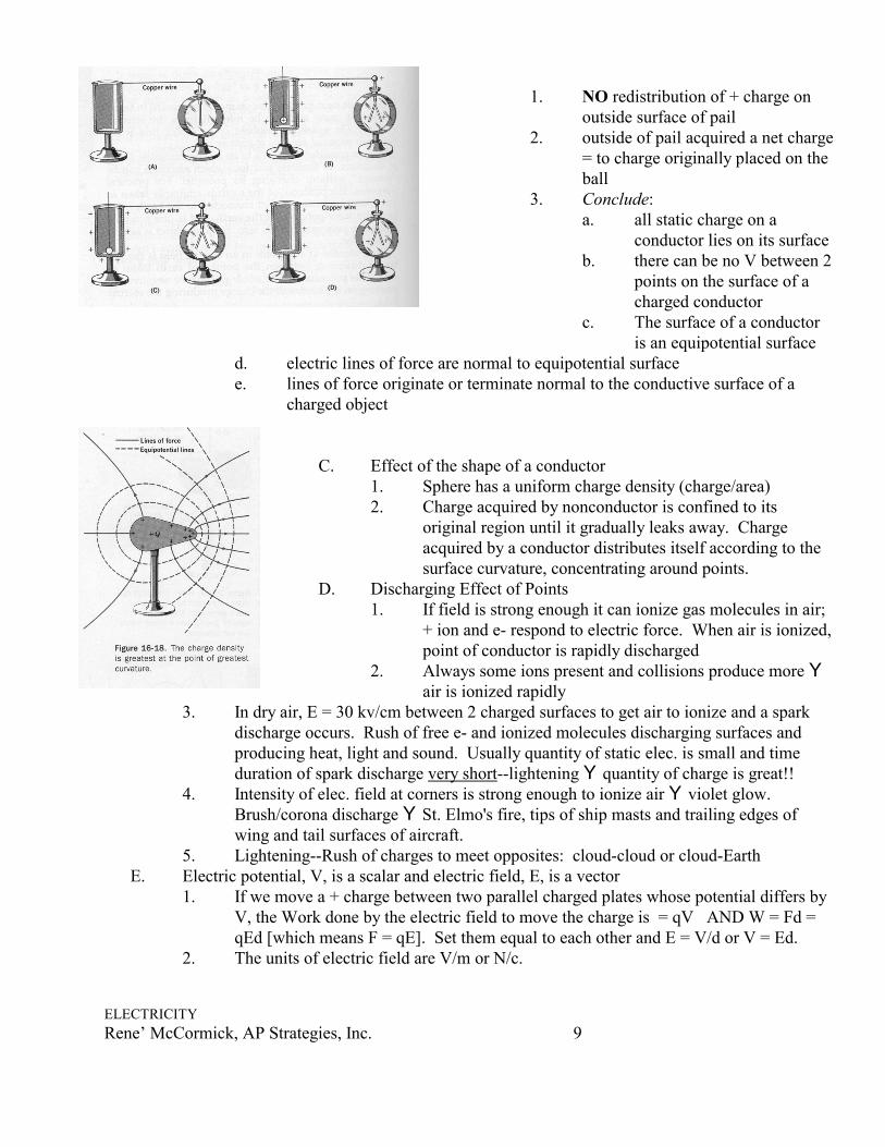
1. NO redistribution of + charge onoutside surface of pail
2. outside of pail acquired a net charge= to charge originally placed on theball
3. Conclude:a. all static charge on a
conductor lies on its surfaceb. there can be no V between 2
points on the surface of acharged conductor
c. The surface of a conductoris an equipotential surface
d. electric lines of force are normal to equipotential surfacee. lines of force originate or terminate normal to the conductive surface of a
charged object
C. Effect of the shape of a conductor1. Sphere has a uniform charge density (charge/area)2. Charge acquired by nonconductor is confined to its
original region until it gradually leaks away. Chargeacquired by a conductor distributes itself according to thesurface curvature, concentrating around points.
D. Discharging Effect of Points1. If field is strong enough it can ionize gas molecules in air;
+ ion and e- respond to electric force. When air is ionized,point of conductor is rapidly discharged
2. Always some ions present and collisions produce more Yair is ionized rapidly
3. In dry air, E = 30 kv/cm between 2 charged surfaces to get air to ionize and a sparkdischarge occurs. Rush of free e- and ionized molecules discharging surfaces andproducing heat, light and sound. Usually quantity of static elec. is small and timeduration of spark discharge very short--lightening Y quantity of charge is great!!
4. Intensity of elec. field at corners is strong enough to ionize air Y violet glow. Brush/corona discharge Y St. Elmo's fire, tips of ship masts and trailing edges ofwing and tail surfaces of aircraft.
5. Lightening--Rush of charges to meet opposites: cloud-cloud or cloud-EarthE. Electric potential, V, is a scalar and electric field, E, is a vector
1. If we move a + charge between two parallel charged plates whose potential differs byV, the Work done by the electric field to move the charge is = qV AND W = Fd =qEd [which means F = qE]. Set them equal to each other and E = V/d or V = Ed.
2. The units of electric field are V/m or N/c.

ELECTRICITYRene’ McCormick, AP Strategies, Inc. 10
Example 1Suppose an electron in the picture tube of a television is accelerated from rest through a potential differenceof +5,000 Va) What is the change in PE of the electron?
b) What is the speed of the electron (m = 9.1 x 10⁻³¹kg) as a result of this acceleration?
c) Repeat for a proton (m = 1.67 x 10⁻²⁷kg) that accelerates through a potential difference of - 5,000 V.
Example 2Two parallel plates are charged to a voltage of 50 V. If the separation between the plates is 0.050 m,calculate the electric field between them

ELECTRICITYRene’ McCormick, AP Strategies, Inc. 11
F. Capacitors--any isolated conductor can retain acharge. Can increase charge until spark--in avacuum, can withstand more charge1. a combination of conduction plates separated
by an insulator that is used to store an electriccharge is known as a capacitora. area of platesb. distance of separationc. char. of insulating material determine
charge that can be placed on capacitor
2. Larger charge--greater is E between platesa. Ratio of q:V is a constant for a given capacitor--Capacitance,C C = ratio
of q:V C = q V
C is measured in farads, C = 1f when a charge of 1 c on a capacitor results in a V of 1v between plates
G. Dielectric Materials--Faraday H. Effect of different insulating materials between plates of capacitors--using plates of equal
area and spacing and comparing with air, C2 had greater charge than C1(air) by a factor of K q2 = Kq1 q2 = K q1 thus C2=KC1 v v
1. Materials used to separate plates of capacitors are known asdielectrics. K, dielectric constanta. dry air K = 1.0006 (unity w/ vacuum)b. dimensionlessc. K = C2
C1
ELECTRICITYRene’ McCormick, AP Strategies, Inc. 12
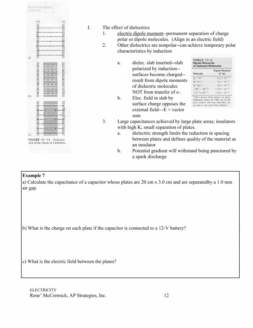
I. The effect of dielectrics1. electric dipole moment--permanent separation of charge
polar or dipole molecules. (Align in an electric field)2. Other dielectrics are nonpolar--can achieve temporary polar
characteristics by induction
a. dielec. slab inserted--slabpolarized by induction--surfaces become charged--result from dipole momentsof dielectric moleculesNOT from transfer of e-.
b. Elec. field in slab bysurface charge opposes theexternal field---E = vectorsum
3. Large capacitances achieved by large plate areas; insulatorswith high K; small separation of plates.a. dielectric strength limits the reduction in spacing
between plates and defines quality of the material asan insulator
b. Potential gradient will withstand being punctured bya spark discharge
Example 7a) Calculate the capacitance of a capacitor whose plates are 20 cm x 3.0 cm and are separatedby a 1.0 mmair gap.
b) What is the charge on each plate if the capacitor is connected to a 12-V battery?
c) What is the electric field between the plates?

ELECTRICITYRene’ McCormick, AP Strategies, Inc. 13
J. Combinations of Capacitors1. C1 ,C 2, C 3 in parallel--1 plate to
1 conductor while another plateconnected to a secondconductor ˆ same V across all
q1 = C1v , q2 = C2v , q3 = C3v qT = q1 + q2 + q3
qT = C1v + C2v + C3v qT = CTv sub CTv = C1v + C2v + C3v
CT = C1 + C2 + C3
2. C1 ,C 2, C 3 in series
q = q1 = q2 = q3 since charge is transferred
vT = v1 + v2 + v3 AND vT = q AND V1 = Q CT C1
CT = 1 1 1 C1 + C2 + C3
SUMMARY:
E = F q C = q E L Electric field intensity V F L Force in Newtons q L test charge in coulombs K = C2
C1 Potential Difference, V = work = w = PE = Ed
charge q q 1 volt = 1 joule 1 coulomb
Capacitors in parallel: CT = C1 + C2 + C3Capacitors in series: CT = 1 1 1 C1 + C2 + C3
ELECTRICITYRene’ McCormick, AP Strategies, Inc. 14
IV. Electric CurrentsA. Volta vs. Galvani–1800ish. Before these guys, all we knew about electricity involved
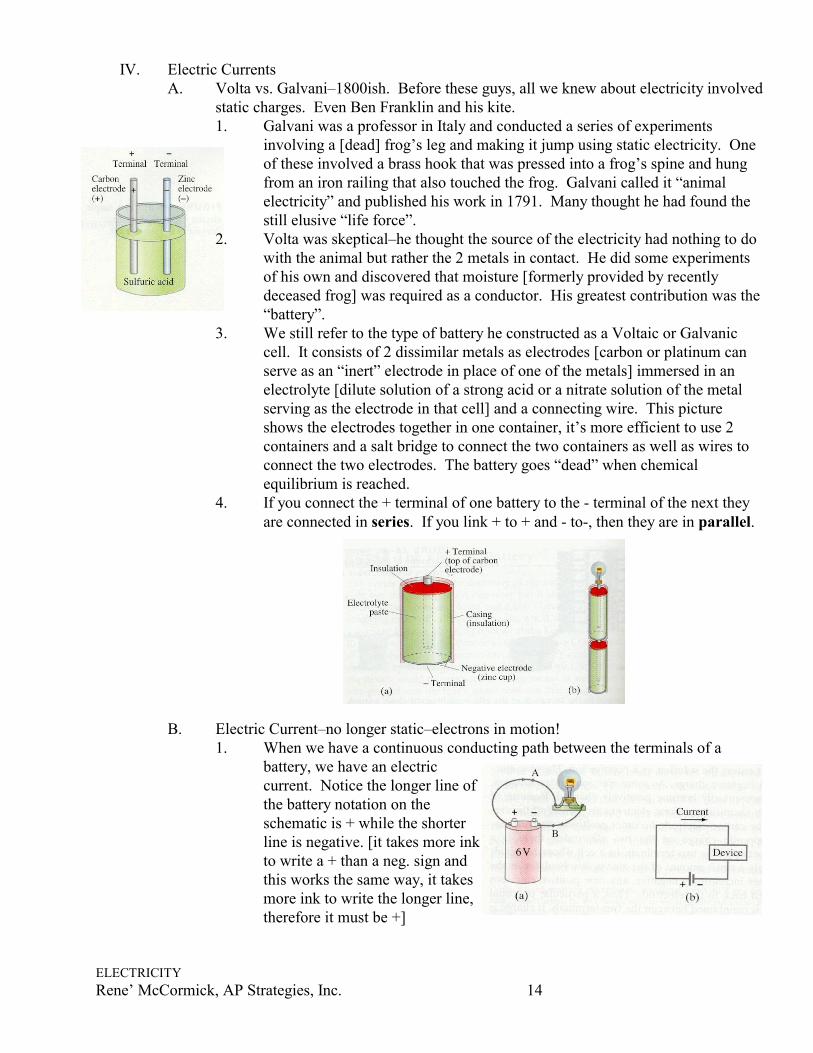
static charges. Even Ben Franklin and his kite. 1. Galvani was a professor in Italy and conducted a series of experiments
involving a [dead] frog’s leg and making it jump using static electricity. Oneof these involved a brass hook that was pressed into a frog’s spine and hungfrom an iron railing that also touched the frog. Galvani called it “animalelectricity” and published his work in 1791. Many thought he had found thestill elusive “life force”.
2. Volta was skeptical–he thought the source of the electricity had nothing to dowith the animal but rather the 2 metals in contact. He did some experimentsof his own and discovered that moisture [formerly provided by recentlydeceased frog] was required as a conductor. His greatest contribution was the“battery”.
3. We still refer to the type of battery he constructed as a Voltaic or Galvaniccell. It consists of 2 dissimilar metals as electrodes [carbon or platinum canserve as an “inert” electrode in place of one of the metals] immersed in anelectrolyte [dilute solution of a strong acid or a nitrate solution of the metalserving as the electrode in that cell] and a connecting wire. This pictureshows the electrodes together in one container, it’s more efficient to use 2containers and a salt bridge to connect the two containers as well as wires toconnect the two electrodes. The battery goes “dead” when chemicalequilibrium is reached.
4. If you connect the + terminal of one battery to the - terminal of the next theyare connected in series. If you link + to + and - to-, then they are in parallel.
B. Electric Current–no longer static–electrons in motion!1. When we have a continuous conducting path between the terminals of a
battery, we have an electriccurrent. Notice the longer line ofthe battery notation on theschematic is + while the shorterline is negative. [it takes more inkto write a + than a neg. sign andthis works the same way, it takesmore ink to write the longer line,therefore it must be +]

ELECTRICITYRene’ McCormick, AP Strategies, Inc. 15
V IR=
2. Note the current flows from + to -. 3. Electric current–the net amount of charge that passes through it per unit time
at any point. I = )Q/)t It’s unit is the ampere, amp, A = 1 C/second4. In any single circuit, the current at any instant is the same at one point as at
any other point since electric charge is conserved.
Example 1A steady current of 2.5 A flows in a wire for 4.0 minutes. a) How much charge passed through any point in the circuit?
b) How many electrons would this be?
Example 2What’s wrong with this picture?
5. Conventional current. It would be a while before anyone knew about electrons. When the rules of this game were being set, everyone assumed positive charge flowedin a circuit. Be clear in your language–conventional current traces the path of positivecharge. Electron current tracks the path of the electron flow and it is opposite toconventional current.
C. Ohm’s Law: Resistance and Resistors1. To produce an electric current in a circuit, a difference in
potential is required. Georg Simon Ohm (17877-1854)determined I % V
2. This is also affected by resistance of a wire or other device tothe flow of current and it varies inversely with current so I =V/R Some physicists take issue with “law”. R is measured inohms, S
Ohm’s Law:

ELECTRICITYRene’ McCormick, AP Strategies, Inc. 16
RLA
=ρ
Example 3A small flashlight bulb draws 300 mA from its 1.5 volt battery.a) What is the resistance of the bulb?
b) If the voltage dropped to 1.2 volt, how would the current change?
All electric devices offer resistance to the flow of current. Filaments in light bulbs and the heating coilsof electric heaters and stoves result in their becoming HOT.
3. Resistors can be used to control theamount of current. The range ofresistors is less than 1 ohm to millionsof ohms. Wire-wound resistors consistof a coil of fine wire and compositionresistors are usually made of thesemiconductor carbon.
4. Resistivity–The R of a metal wire isdirecly % to its length, L, and inverselyproportional to the corss-sectionalarea, A. Where rho is a resistivity anddepends on the material used.

ELECTRICITYRene’ McCormick, AP Strategies, Inc. 17
Example 4Suppose you want to connect your stereo to remote speakers.a) If each wire must be 20 m long, what diameter copper wire should you use to keepthe resistance less than 0.10 S per wire?
b) If the current to each speaker is 4.0 A, what is the voltage drop across each wire?
Example 5A wire of resistance R is stretched uniformly until it is twice its original length. What happens to itsresistance? Justify.
D. Electric Power1. Electric heaters, stoves, toasters and hair dryers convert
electrical energy into thermal energy. In a lightbulb the tinywire filament becomes so hot it glows. Only a few percent ofthe energy is transformed into visible light, 90% is convertedinto thermal energy.
2. Collisions between the electrons and the atoms of the metal conductor cause the heatto be produced. The KE of the electron is transferred to the metal’s atom andincreases its KE which raises the temperature.
3. P = power = energy transformed = QV Time t
4. The charge that flows per unit second, Q/t is simply the electric current, I so...
P = IV= I2R = V2/RUse V = IR to generate the other forms:P = IV = I (IR)
= (V/R)V
ELECTRICITYRene’ McCormick, AP Strategies, Inc. 18
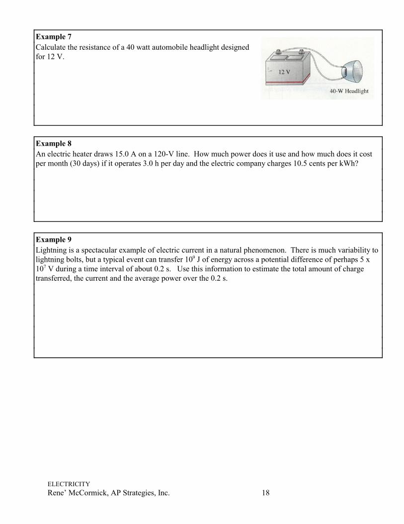
Example 7Calculate the resistance of a 40 watt automobile headlight designedfor 12 V.
Example 8An electric heater draws 15.0 A on a 120-V line. How much power does it use and how much does it costper month (30 days) if it operates 3.0 h per day and the electric company charges 10.5 cents per kWh?
Example 9Lightning is a spectacular example of electric current in a natural phenomenon. There is much variability tolightning bolts, but a typical event can transfer 109 J of energy across a potential difference of perhaps 5 x10⁷ V during a time interval of about 0.2 s. Use this information to estimate the total amount of chargetransferred, the current and the average power over the 0.2 s.

ELECTRICITYRene’ McCormick, AP Strategies, Inc. 19
V. DC CIRCUITSA. Circuit diagrams–A short-hand way of depicting the components in
a direct current [battery] circuit.B. Resistors in Series–2 or more resistors are connected end to end.
Resistors could be simple resistors [the striped things] or lightbulbs, heating elements, or other resistive devices. 1. I is equal across all resistors in a series2. V = V1 + V2+ V3 = IR1 + IR2 + IR3 My students came up
with a clever way to remember this. They had “Sr. V” as in
seniors are victorious. It helped them remember that inSERIES, Resistors & Voltage are additive. {They alreadyknew that capacitor behave “opposite” to resistors.}
3. Equivalent Resistor–Since resistors are additive in series, you can replace all thosezig-zag’s with one equivalent [the sum of ] zig zag like the picture above on the farright. The relationship is V = I Req. This simplifies things!
C. Resistors in parallel– Here the current from the source splits into two or more branches. This is how the wiring in buildings and houses is done. This way, if you disconnect onedevice, the current to the others is not disrupted. With series, if one goes out, the current isstopped!1. I is split across the branches and is therefore additive
I = I1 +I2 + I3 WHERE EACH I = V/it’s R AND total I = V/Req
ELECTRICITYRene’ McCormick, AP Strategies, Inc. 20
2. It follows that This means that the NET resistance in1 1 1 1
1 2 3R R R Req= + +
parallel is LESS than any single resistor since you are giving the current additionalpaths to follow, hence the resistance will be less.
3. Here’s an analogy: Consider 2 pipes taking in water near the top of a dam andreleasing it below as shown here. Thegravitational potential difference, % h, isthe same for both pipes, just as in theelectrical case of parallel resistors. If bothpipes are open, rather than only one, twiceas much current will flow through. This,with 2 equal pipes open, the net resistanceto the flow of water will be reduced byhalf.
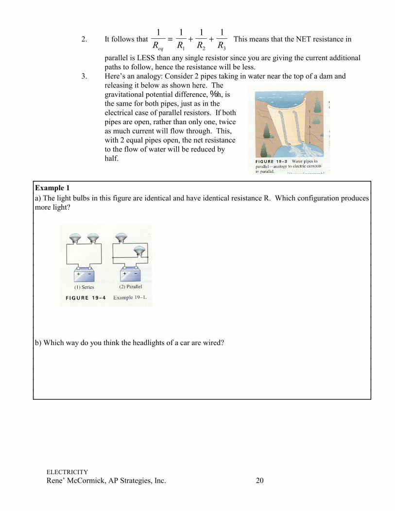
Example 1a) The light bulbs in this figure are identical and have identical resistance R. Which configuration producesmore light?
b) Which way do you think the headlights of a car are wired?

ELECTRICITYRene’ McCormick, AP Strategies, Inc. 21
Example 2Two 100-S resistors are connected (a) in series and (b) in parallel, to a 24.0 V battery. What is the currentthrough each resistor and what is the equivalent resistance of each circuit?
Note that whenever a group of resistors is replaced by Req, I and V and P in the rest of the circuit areunaffected.Example 3How much current flows from the battery in this diagram?

ELECTRICITYRene’ McCormick, AP Strategies, Inc. 22
Example 4What is the current flowing through the 500 S resistor?
Example 5 The circuit shown has three identical light bulbs, each of resistance R. a) When switch S is closed, how will the brightness of bulbs A & Bcompare with that of bulb C?
b) What happens when switch S is opened? Use a minimum ofmathematics in your answers.
Example 6Estimate the equivalent resistance of the “ladder” of equal 100 S resistorsshown. In other words, what would an ohmmeter read if connected betweenpoints A and B?

ELECTRICITYRene’ McCormick, AP Strategies, Inc. 23
D. EMF and Terminal Voltage–A device such as a battery or an electric generator thattransforms one type of energy (chem., mech, light, etc.) into electrical energy is called a seator source of electromotive force or emf or õ . The potential difference between theterminals of such a source, when no current flows to an external circuit is called the emf ofthe source. So, you see, it’s not a force measured in Newtons–it’s measured in VOLTSsince it’s a measure of potential difference.1. Ever notice that if you turn the headlights on in your car BEFORE starting it, that the
headlight’s dim during the start process? That’s due to the fact that the lead storagebattery’s electron’s flow isn’t fast enough to supply the charge you demandinstantaneously. Every battery has internal resistancesymbolized by r.
2. Terminal voltage–when there is no current drawnfrom the battery, Vab = õ. Once you start to draw acurrent, I, the internal resistance of the battery kicks inand the actual voltage delivered is what we call theterminal voltage and is calculated
Vab = õ - Ir
Example 7A 9.0 V battery whose infernal resistance, r, is 0.50 S is connected in the circuitshown.a) How much current is drawn from the battery?
b) What is the terminal voltage of the battery?
c) What is the current in the 6.0 S resistor?

ELECTRICITYRene’ McCormick, AP Strategies, Inc. 24
VI. Kirchhoff’s RulesA. These rules were invented in the mid 1800's to deal with complicated circuits. There are 2
rules and they are simply convenient applications of the laws of conservation of charge andenergy.
B. Kirchhoff’s first rule–the junction rule, based on the conservation of charge which wealready used in deriving the rule for parallel resistors.
At any junction point, the sum of all currents entering the junction must equal the sum of all currents leaving the junction.
“What goes in must come out!” Charges entering a junction must also leave–none is lost
or gained.C. Kirchhoff’s second rule–the loop rule, based on
the conservation of energy.The sum of the changes in potential around any closed path of a circuit must be zero.
D. Examine the junction at point a. I3 is enteringwhereas I1 and I2 are leaving. The junction rule states that I3 = I1 + I2
E. Examine this circuit [you’ll get your chance with the above circuit in our next exampleproblem].1. I = 12.0 V / 690 S = .0174 A2. The + side e has more potential than d3. Follow a + test charge from point e,
point d is taken as zero. When we returnto e, the potential there will be the sameas when we started.
4. From e ÷ a, no change since no sourceof V or R.
5. From a ÷ b, there is a voltage drop ofV= IR = 0.0174 A x 400 S = 6.96 V[the + charge is flowing “downhill”toward the negative terminal]. Use anegative sign to show the drop in V. V ba = Va -Vb = -6.96 V
6. From b ÷ c, further voltage drop V = IR= 0.0714 A x 290 S = 5.04 S which wegive a negative sign since it is a drop involtage.
7. From c ÷ d, there is no change involtage.
8. From d ÷ a, there is a POSITIVE 12.0 Voltage increase.9. Therefore the sum of all the changes in potential is
-6.96 V - 5.04 V + 12.0V = 0 Thus, the loop rule is satisfied.

ELECTRICITYRene’ McCormick, AP Strategies, Inc. 25
Example 8Calculate the currents I1 , I2, and I3 in each of the branches of this circuit.
F. EMFs in Series and in Parallel; Charges in a Battery1. Series arrangement–Remember “Sr. V”, in series V’s
and R’s are additive so the voltage is the sum of theseries EMFs.
2. Figure b has the batteries attached OPPOSITELY sosubtract 20V-12V = 8V. Follow the positive testcharge from a to c. Seems wasteful? This is howalternators in cars and battery chargers work. Itforces electrons to the negative terminal removingthem from the positive.
3. Figure c shows parallel–used when provide more Isuch as starting a diesel engine. V’s are equal inparallel so each cell has to produce only a fraction ofthe total current, so the loss due to internal resistance

ELECTRICITYRene’ McCormick, AP Strategies, Inc. 26
is less than for a single cell; batteries go dead less quickly.G. Circuits containing Capacitors in Series and in Parallel
1. In series R’s are additive. In parallel R’s are reciprocal and additive
2. In series C’s are reciprocal and additive. In parallel, C’s are additive. 3. Q1 = CV1 and Q2 = CV2 etc.. The total charge that must leave the battery is Q =
Q1 +Q2..., so Q = CeqV What is really happening by adding capacitors in series isthat we are increasing the effective area of the plates so that total or equivalent
capacitance increases.Example 9Determine the capacitance of a single capacitor that will have the sameeffect and the combination shown here. Take C1 = C2 = C3 = C
H. RC Circuits–those containing both a resistor and a capacitor.
1. Close the switch S. Electrons will flow out of the negative terminal and accumulate[ a negative charge] on the upper place of the capacitor. AND electrons will flowinto the + terminal of the battery leaving a + charge on the other [lower] plate of thecapacitor.

ELECTRICITYRene’ McCormick, AP Strategies, Inc. 27
2. As charge accumulates on the capacitor, the potential difference, V, across itincreases and the current is reduced until eventually the V across the capacitor equalsthe emf of the battery, õ. Now there is no potential difference across the R and nofurther current flow!

ELECTRICITYRene’ McCormick, AP Strategies, Inc. 28
3. The potential difference across the capacitor, which is proportional to the charge onthe capacitor [V = Q/C] thus increases in time. Note this is an exponential curve.
4. What if we discharge the charged capacitor? No battery needed for this:
5. When the switch is closed, charge begins to flow through resistor R from one side ofthe capacitor toward the other side, until it is fully discharged. Note this curvefollows one of exponential decay.
Summary:
“Sr. V”–nemonic to help you remember what’s additive and what’s equal in series vs. parallel circuits. Resistors are “opposite” to capacitors and are the only components that have the “reciprocal and additive” thing going on! V’s and I’s are either additive or equal
Sr. V means in Series, R ‘s & V ‘s are additive, so that means that C’s must be additive and reciprocalwhile I’s must be equal.
Turn all of that around and that means that for parallel, R is reciprocal and additive while C is just additiveand V’s are equal while I must be additive.
Series [think Sr.V] Parallel
Req = R1 + R2 + R3... 1/Req = 1/R1 + 1/R2 +1/R3 ...
1/Ceq = 1/C1 + 1/C2 +1/C3 ... Ceq = C1 + C2 + C3...
VT = V1 + V2 + V3... VT = V1 = V2 = V3...
IT = I1 = I2 = I3... IT = I1 + I2 + I3...