FOOD MICROBIOLOGY MEDI 2371 Prepared BY PROF. MOHAMMAD EID SHUBAIR.

Electronics - PHYS 2371/2
TODAY □ Quick Review-Basics
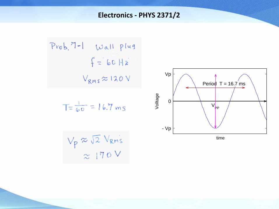
□ Alternating Current, Ch-7 - RMS - problem 7-1
□ Elements of AC Circuits, Ch-8 - resistor, capacitor, inductors(L) - impedance (Z), reactance (X)
(video break)
□ Step Function Analysis, Ch-12 - RC circuit, LR circuit
□ Power Supply, Ch-38 - diode rectifiers, filtering
□ Lab-3, Time-varying Voltages - oscilloscope, RC circuit, - power supply filtering
HWs due on Fridays
HW (Chs. 7,8,12) due this Friday, Sept. 23
Lab-3 report due Wednesday, Sept. 28

Electronics - PHYS 2371/2

Electronics - PHYS 2371/2
Review Basics
Kirchhoff’s Basic Circuit Laws
• KCL – Kirchhoff’s Current Law Σ I = 0 at node
• KVL – Kirchhoff’s Voltage Law Σ V = 0 around loop
Adding components
• Rseries = Σ Ri , 1/Rparallel = Σ 1/Ri
• Cparallel= Σ Ci , 1/Cseries = Σ 1/Ci
Voltage Divider
• V2-out = Vin R2/(R1+R2)
• http://www.falstad.com/circuit/e-voltdivide.html
Gustav Robert Kirchhoff (1824 – 1887)
- Born in Königsberg, East Prussia (now Kaliningrad, Russia) graduated from the Albertus University of Königsberg, moved to Berlin, then received a professorship at Breslau (now Wroclaw, Poland). He contributed to the fundamental understanding of electrical circuits. Kirchhoff formulated his circuit laws, which are now ubiquitous in electrical engineering, in 1845, while still a student. He completed this study as a seminar exercise; it later became his doctoral dissertation. In 1857 he calculated that an electric signal in a resistanceless wire travels along the wire at the speed of light. He proposed his law of thermal radiation in 1859, and gave a proof in 1861. He also investigated spectroscopy and the emission of black-body radiation by heated objects. He coined the term "black body" radiation in 1862.

Electronics - PHYS 2371/2
0
- Vp
Vp
VPP
Period T
time
Vo
llta
ge
frequency, (Hz or cycles/s)
period
peak-to-peak voltage
2
21T =
2PP P
f
f
V V
( ) sin
AC - Alternating Current (Ch-7)
Sinewave
frequency, units rad/s
phase, units radia
( )
ns
PV t V t
How do you measure the power for AC?
For DC, Power = IDC x VDC
Both I and V are constant.
With AC, I(t) and V(t)

Electronics - PHYS 2371/2
RMS – root mean square Averaging for AC signals (voltage or current)
Electronics - PHYS 2371/2
0
- Vp
Vp
VPP
Period T = 16.7 ms
time
Vo
llta
ge

Electronics - PHYS 2371/2
Basic Elements of AC Circuits
R-Ohm (Ω)
C-Farad (F)
L-Henry (H)

Electronics - PHYS 2371/2
Resistors various types
Carbon composition
Carbon/metal film
Wire wound
Electronics - PHYS 2371/2
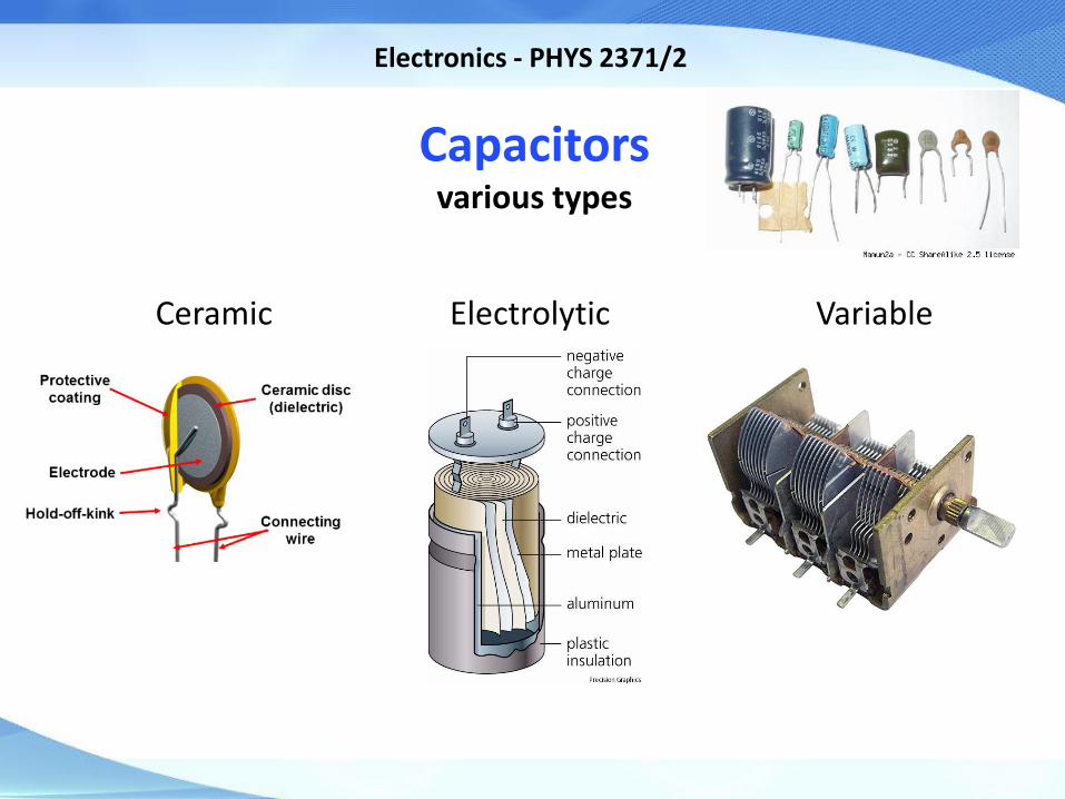
Capacitors various types
Ceramic Electrolytic Variable

Electronics - PHYS 2371/2
Inductors various types
Simple Toroidal Iron Core or Ferrite

Electronics - PHYS 2371/2
Inductor
An inductor is a passive two-terminal electrical component which resists changes in electric current passing through it. When a current flows through it, energy is stored temporarily in a magnetic field in the coil. When the current flowing through an inductor changes, the time-varying magnetic field induces a voltage in the conductor, according to Faraday’s law of electromagnetic induction, which opposes the change in current that created it. (wikipedia)

Electronics - PHYS 2371/2
Examples of Phase Shift V(t) and I(t) may not be “in phase”
Relation between Voltage and Current Time dependence of V(t) and I(t)

Electronics - PHYS 2371/2
R C L
I(t) = V(t)/R C dV(t)/dt -1/L ∫V(t)dt
V(t) = I(t) R 1/C ∫I(t)dt L dI(t)/dt
Z = R -i/ωC iωL
X = |Z|= R 1/ωC ωL
φ 0 V lags I by 90°
V leads I by 90°
What are I-V relationships for any time-dependent voltages
Impedance Z = V/I Z is a complex number containing the Resistance and
the V-I phase difference (introduce i=√-1)

Electronics - PHYS 2371/2
Series components ZT = ∑ Zi = Z1+Z2
Reactance X = |Z| the magnitude of Z

Electronics - PHYS 2371/2
Power Dissipated Power is dissipated (heat) in R only,
C and L only store energy

Electronics - PHYS 2371/2
ZR = R ~ R
ZC = -i /ωC ~ 1/C
Series components
ZT = ∑ Zi = Z1+Z2····
Parallel components
1/ZT = ∑ 1/Zi = 1/Z1+1/Z2····
Series components
RT = ∑ Ri = R1+R2····
1/CT = ∑ 1/Ci = 1/C1+1/C2····
Parallel components
1/RT = ∑ 1/Ri = 1/R1+1/R2····
CT = ∑ Ci = C1+C2····
Combining Impedances

Electronics - PHYS 2371/2
Video
From the Tesla video last week, what do you think about:
(1) transmitting power through the air; (2) giving it for free (how to charge people)?

Electronics - PHYS 2371/2
Tesla Video Why is AC better than DC for power applications?
AC allows for lower transmission losses, by increasing voltage and reducing current.
Using a few assumptions, the power loss in
transmission through power lines with resistance R is
P = I2 R.
Thus, the power loss is proportional to ~ I2.
You can keep the delivered power (P=IV) constant
by simply increasing the voltage by the factor , and
reducing the current by the same factor of .
So increasing the voltage by a factor of 2 and
decreasing the current by a factor of 2, keeps the
delivered power constant, but reduces the power loss
in the power lines by a factor of 22 = 4.
Power grids use voltages up to nearly 106 volts.
This effect is only useful with AC, as it is very easy
to step up and down the voltages with
passive electrical transformers.
Auto Battery
Automobiles increased the battery voltage from 6 VDC to 12 VDC in ~1955, in order to decrease the current.
POWER GRID Voltage
GigaW Power plant 138-500 kVAC
Large substation 26/69 kVAC
Small substation 13,800 VAC
street 4,000 VAC
house 120/240 VAC

Electronics - PHYS 2371/2
http://www.falstad.com/circuit/e-cap.html
Step Function Analysis (Ch. 12)
Step function analysis of RC circuit

Electronics - PHYS 2371/2
http://www.falstad.com/circuit/e-induct.html
Step function analysis of LR circuit

Electronics - PHYS 2371/2
Power Supply (Ch. 38) Want to convert AC to DC
RC
Surf Youtube for rectifier tutorials

Electronics - PHYS 2371/2
USB Power Supply What’s inside?
http://www.righto.com/2014/05/a-look-inside-ipad-chargers-pricey.html https://www.youtube.com/watch?v=w6ZG8ExMV8U

Electronics - PHYS 2371/2
Lab Experiment – 2
The Oscilloscope And
Time-dependent Voltages
Prepare for Prelab Quiz on Friday
Electronics - PHYS 2371/2
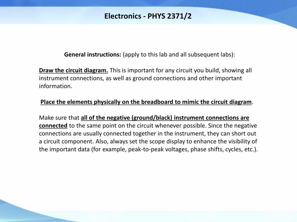
General instructions: (apply to this lab and all subsequent labs): Draw the circuit diagram. This is important for any circuit you build, showing all instrument connections, as well as ground connections and other important information. Place the elements physically on the breadboard to mimic the circuit diagram. Make sure that all of the negative (ground/black) instrument connections are connected to the same point on the circuit whenever possible. Since the negative connections are usually connected together in the instrument, they can short out a circuit component. Also, always set the scope display to enhance the visibility of the important data (for example, peak-to-peak voltages, phase shifts, cycles, etc.).
Electronics - PHYS 2371/2
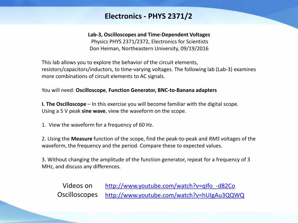
Lab-3, Oscilloscopes and Time-Dependent Voltages Physics PHYS 2371/2372, Electronics for Scientists Don Heiman, Northeastern University, 09/19/2016
This lab allows you to explore the behavior of the circuit elements, resistors/capacitors/inductors, to time-varying voltages. The following lab (Lab-3) examines more combinations of circuit elements to AC signals. You will need: Oscilloscope, Function Generator, BNC-to-Banana adapters I. The Oscilloscope – In this exercise you will become familiar with the digital scope. Using a 5 V peak sine wave, view the waveform on the scope. 1. View the waveform for a frequency of 60 Hz. 2. Using the Measure function of the scope, find the peak-to-peak and RMS voltages of the waveform, the frequency and the period. Compare these to expected values. 3. Without changing the amplitude of the function generator, repeat for a frequency of 3 MHz, and discuss any differences.
http://www.youtube.com/watch?v=qIfo_-d82Co
http://www.youtube.com/watch?v=hUIgAu3QQWQ
Videos on Oscilloscopes

Electronics - PHYS 2371/2
II. Time Response of an RC circuit – Here you will explore the response of an RC (resistor/capacitor) circuit to a voltage pulse. Construct a circuit consisting of a C=0.1 μF capacitor and an R=2 kΩ resistor in series, and connect to the function generator. Use the “TTL” output from the function generator to obtain a square wave with voltage alternating between +5 V and 0 V. Note that this is equivalent to switching a DC voltage on and off. View the voltage across function generator on chnl-1 of the scope and the voltage across the capacitor (VC) on chnl-2. Make sure you consider that the scope has a single ground (outer contact on the BNC connector), so you don’t short out one circuit element. 1. First, compute the time constant C=RC and frequency fo=1/(2π τC). View the voltage waveforms, VC(t),
for three frequencies f determined by the relations,
f << fo, f ~ fo, and f >> fo. Make sure Vin is always +5 V to 0 V. Adjust the scope settings to display all the important quantities. Capture the scope waveform in Excel. Make a plot of all 3 waveforms. Print out and discuss the results. 2. At one frequency, where f < fo, determine the circuit time constant, τC, from the time it takes for the capacitor voltage, VC(t), to drop to 1/e of any starting value. Compare the measured time constant to RC, including the uncertainties in R and C. 3. Next, for f ~ fo view the voltage on the resistor with the scope, VR(t), by exchanging the capacitor and resistor. Explain what you observe. Why is the voltage positive and negative?
http://www.youtube.com/watch?v=mLKPwWGBtIw
http://www.youtube.com/watch?v=LAdEyEOOBjU Videos on
Function Generators
Electronics - PHYS 2371/2
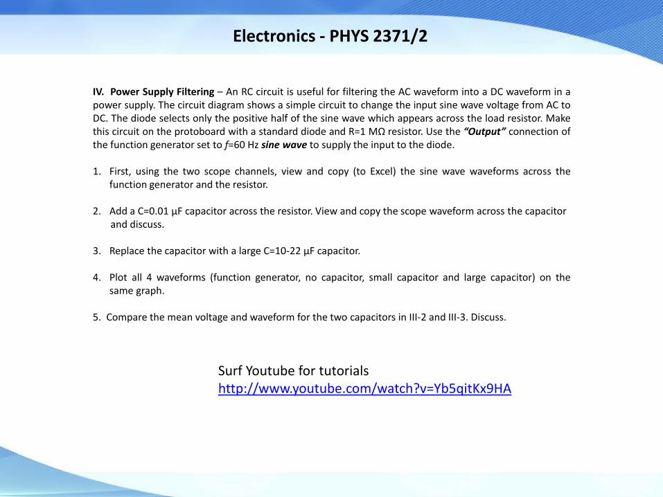
IV. Power Supply Filtering – An RC circuit is useful for filtering the AC waveform into a DC waveform in a power supply. The circuit diagram shows a simple circuit to change the input sine wave voltage from AC to DC. The diode selects only the positive half of the sine wave which appears across the load resistor. Make this circuit on the protoboard with a standard diode and R=1 MΩ resistor. Use the “Output” connection of the function generator set to f=60 Hz sine wave to supply the input to the diode. 1. First, using the two scope channels, view and copy (to Excel) the sine wave waveforms across the
function generator and the resistor.
2. Add a C=0.01 μF capacitor across the resistor. View and copy the scope waveform across the capacitor and discuss. 3. Replace the capacitor with a large C=10-22 μF capacitor.
4. Plot all 4 waveforms (function generator, no capacitor, small capacitor and large capacitor) on the
same graph.
5. Compare the mean voltage and waveform for the two capacitors in III-2 and III-3. Discuss.
Surf Youtube for tutorials http://www.youtube.com/watch?v=Yb5qitKx9HA

Electronics - PHYS 2371/2
Teach logic gates and build circuits - http://logic.ly/
Drawing Circuits (free)
Digikey – http://www.digikey.com/schemeit#
CircuitLab – https://www.circuitlab.com/ (Export as png file)
XCircuit – http://opencircuitdesign.com/xcircuit/
SmartDraw – http://www.smartdraw.com/software/electrical.asp

Electronics - PHYS 2371/2
Ende