ELECTRONICS INDUSTRY MODULE - p2infohouse.org · This industry module is designed to provide...
78
5 , -37 /j&C ..J : 3 A THE MASSACHUSETTS TOXICS USE REDUCTION INSTITUTE University of Massachusetts at Lowell One University Avenue Lowell, MA 01854 Telephone: (508) 934-3275 FAX: (508) 453-2332 ELECTRONICS INDUSTRY MODULE TOXICS USE REDUCTION PLANNER CERTIFICATION COURSE by Joel Pointon
-
Upload
trinhkhuong -
Category
Documents
-
view
218 -
download
0
Transcript of ELECTRONICS INDUSTRY MODULE - p2infohouse.org · This industry module is designed to provide...
5 , - 3 7 / j & C ..J : 3 A
THE MASSACHUSETTS TOXICS USE REDUCTION INSTITUTE
University of Massachusetts at Lowell One University Avenue Lowell, MA 01854 Telephone: (508) 934-3275 FAX: (508) 453-2332
ELECTRONICS INDUSTRY MODULE
TOXICS USE REDUCTION PLANNER CERTIFICATION COURSE
by Joel Pointon

1
n
Acknowledgments
My thanks to the following individuals for their assistance in obtaining information used in this presentation.
S.K. Hammond, PhD, Associate Professor, University of Massachusetts Medical School at Worcester n Robert Witowski, Engineer, SEMATECH, Austin, Texas
D I j_ 1 3 3 1 3
Frank Marino, Engineer, Raytheon Inc., Concord, Massachusetts
-
Rose Sweeney, Engineer, Shipley Co., Marlboro, Massachusetts
Jack L u s h and Mark Griffon of the Toxics Use Reduction Institute, University of Massachusetts at Lowell, Lowell, Massachusetts
3 J

7
< . 7 L. 1
3
i- 1 3 3
TOXIC ,USE REDUCTION PLANNING
IN THE ELECTRONICS INDUSTRY
TABLE OF CONTENTS
1. INTRODUCTION ........................................ 1.
II. INDUSTRY OVERVIEW ............................... 2.
111. PROCESS CHARACTERIZATION ................. .24
IV. TOXIC USE REDUCTION OPTIONS ............... 26 3 -
REFERENCES ............................................. 38
SUPPLEMENTAL READINGS ......................... 43
11

E
c
c_

1 3
I. Introduction
1 n L I
n 3
This industry module is designed to provide participants with an overview of the electronics industry, with specific attention being paid to printed circuit board inanufacturing and semiconductor (or integrated circuit) manufacturing, and their various support operations, The objective is to provide participants with the basic vocabulary and basic process knowledge that will enable them to interact effectively with members of a TURA Team within these industry segments. The material will seek to identify those areas of particular concem to the TURA process, review the variety of process characterization approaches and consider some of the options presently being examined within this industry.
The audience for this segment will comprise those from the regulatory field, consulting services and professionals in the electronics field. It is hoped that with the variety and resources available within this group that the process will be an interactive one, and that participants will not hesitate to contribute their experiences and expertise. The scope of the module is in some ways very general. The industry overviews are designed to provide a basic blueprint of processes and not to be an in depth study in procedures. While we will be providing several useful models and outlines for use in the TURA planning process for these two industry segments, it is hoped that these will prove useful in looking at the broad spectrum of industry segments that make up the electronics field.
3 3 n
a 3 -1-
II. Industry Overview
The Electronics Industry
As an industry, electronics is generally regarded as a relatively "clean" industry by the public at large relative to chemical usage and environmental hpact. The origins of "electronics manufacturing" are traceable to the earliest applications for the use of electrical power to produce useful and timesaving services in the arcas of power for mechanical system, communi- cations and lighting. Over time a myriad of industries have developed that rely on the use of electronic components to produce the technological diversity that is a part of our everyday life. Everything from watches to supercomputers now utilize the support of sophisticated electronics to function with remarkable levels of reliability and performance.
The first segment of this module will focus on the primary building blocks of the electronics industry today: printed circuit boards and integrated circuits.
Objectives:
0 Outline the basic processes involved in the manufacture of printed circuit boards and integrated circuit fabrication.
Familiarize participants with the basic vocabulary used for these manufacturing segments.
-2-
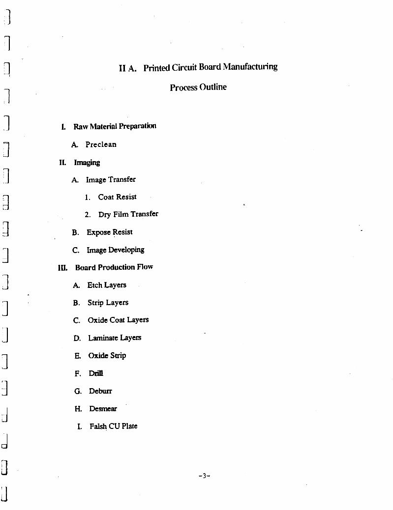
I1 A. Printed Circuit Board Manufacturing
Process Outline
I. Raw Material Preparation
A Preclean
11. Imaging
A. Image Transfer
1 . Coat Resist
2. Dry Film Transfer
B. Expose Resist
C. ImageDeveloping
1U. Board Production Flow
A. EtchLayers
B. Strip Layers
C. Oxide Coat Layers
D. LaminateLayerS
E. Oxide Strip
F. Drill
G. Deburr
H. Dcsmear
I. Falsh CU Plate
-3-
F
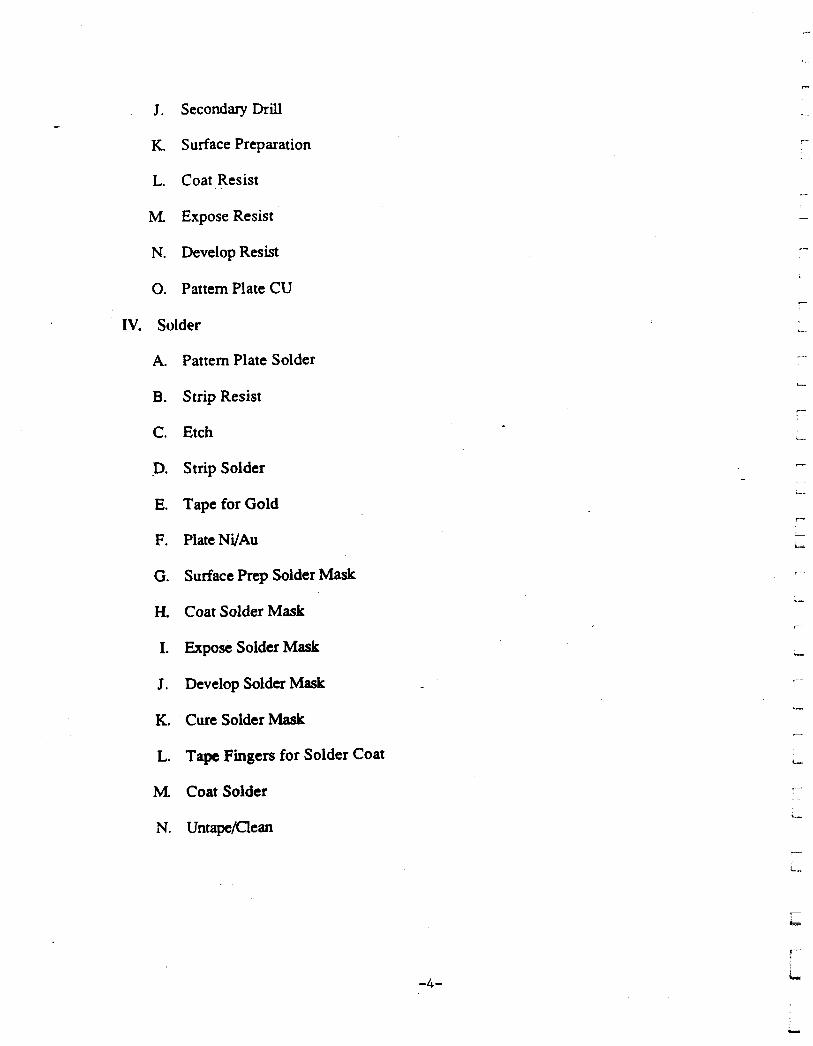
J . Secondary Drill
K. Surface Preparation 7
L. Coat Resist
M. Expose Resist
N. Develop Resist .-
0. Pattern Plate CU - IV. Solder
A. Pattern Plate Solder L_.
B. Strip Resist
C. Etch
.D. Strip Solder
c
-
.-
E. Tape for Gold
F. PlateNYAu
G. Surface Prep Solder Mask
H, Coat Solder Mask
I. Expose Solder Mask
J . Develop Solder Mask
K. Cure Solder Mask
L. Tape Fingers for Solder Coat
A 4 Coat Solder
N. UntapeDean
L
-4-
?
L
1 ,
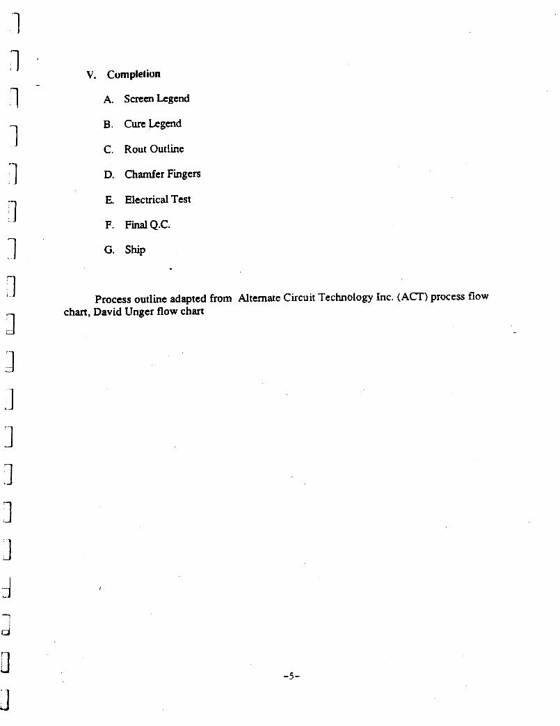
V. Complelion I
1 L
A. ScrcenLegend
1 :-I :I n
B. CureLegend
C. Rout Outline
D. Chamfer Fingers
E. Electrical Test
F. FinalQ.C.
G. Ship
Process outline adapted from Alternate Circuit Technology Inc. (ACT) process flow chart, David Unger flow chart 3
3
I
-5-

I
I
BASIC
CIRCUIT TECHNOLOGY INC. 8240, Ward Hil l , MA 01835 - (508) 372-0200
AND ALTERNATE CIRCUIT
DESIGN TECHNOLOGY INC. "guuitty ora Twne" 34 Rogon Rood, P.O. Box 8240, Word Hili, MA 01835 - (508) 373-620
PRESENTS
MANUFACTURING SEMINAR
-6-

1 1 1 ’I 1 3 1 J 1 3 1 1 1 3 :I 4. a 3 J
15pRlNrS j
LAYER PRODUCTION FLOW CHART
MVELOP RESIST
WTERLAL
AUDIT
O.C. AUDV INSP.
PRECLEAN
PIECE
4
1
Y-J RESlg
PUNCH RECISFRATION
H O E S
FIRS ‘IECE % INSP . O.C. t
i EXPOSE RESIST
LAYERS
MATERM PREP.
AUDIT INSP.
PRECLEAN F I R S PIECE
PUNCH INSP.
PIECE EXPOSE
INSP. WRY
o x . AUDIT .: INSP.
COAT u m
Q.C. AUDIT * INSP. -
-7-
LAYERS 5 / 6
I AUDIT IlNSP I
PRECLEAN UYERS
PIECE INSP.
PUNCH
HOLES I O.C. I A

-8-
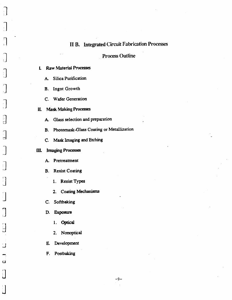
I1 B. Integrated Circuit Fabrication Processes
Process Outline
I. Raw Material Ptocesses
A. Silica Purification
B. Ingot Growth
C. Wafer Generation
11. Mask Making Processes
A. Glass selection and preparation
B. Photomask-Glass Coating or Metallization
C. Mask Imaging and Etching
LII. ImagingProcesses
A. Pretreatment
B. Resist Coating
1. ResistTypcs
2. CoatingMechanisms
C. Softbaking
D. Exposure
1. OplCal
2. Nonoptical
E. Development
F. Postbaking
-9-
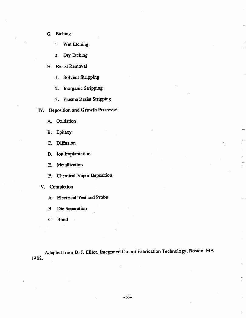
G. Etching
1. Wet Etching
2. Dry Etching
H. Resist Removal
1. Solvent Stripping
2. Inorganic Stripping
3. Plasma Resist Stripping
IV. Deposition and Growth Processes
A. Oxidation
B. Epitaxy
C. Diffusion
D. Ion Implantation
E. Metallization
F. Chemical-Vapor Deposition
V. Completion
A. Electrical Test and Probe
B. Die Separation
C. Bond
Adapted from D.. J. Elliot, Integrated Circuit Fabrication Technology, Boston, MA 1982.
-10-

1 1 1 n :1 3 1 I. . .
-1 1-
.. .-
U
P 1 'J;
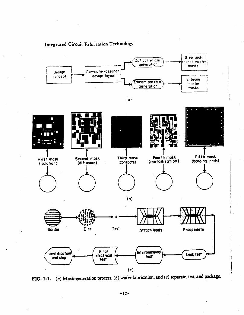
In tcgra t cd Circuit Fabrication Tcc hnolqy
I First mosk (isolation 1
h t
Seconh mask (dit fusion)
fhtrd mask (contocts)
h I
i - fourth mask (meta I I I Lot i on 1
f if th' mask (Sonding pads) I I I
0 0 I I
( c ) I
I
FIG. 1-1. (a) Mask-generation process, (6) wafer fabrication, and (c) separate, test, and p a w e .
-12-

0 0 0 0 0 0 0 0
IO - Lbm partICl0
1. Silicon dust 2. Atmospheric dust 3. Abrasive particles 4. Lint 5. Organic panicla, such at photomist or bactvia
1 Rotating
Crucible
FIG. 1-3. Single-crystal growth.'
-13-
RF or resistance heating coils
I d 0 0
S M o l t e n 0 silicon
0 0 0

1 Wofer 1
1 Wafer I
1 wafer I Light
I- Wafer i
t Wafer I Negative resist
developed
I Wafer I Positive resist
developed
FIG. 1-6. Resist imaging.
-14-
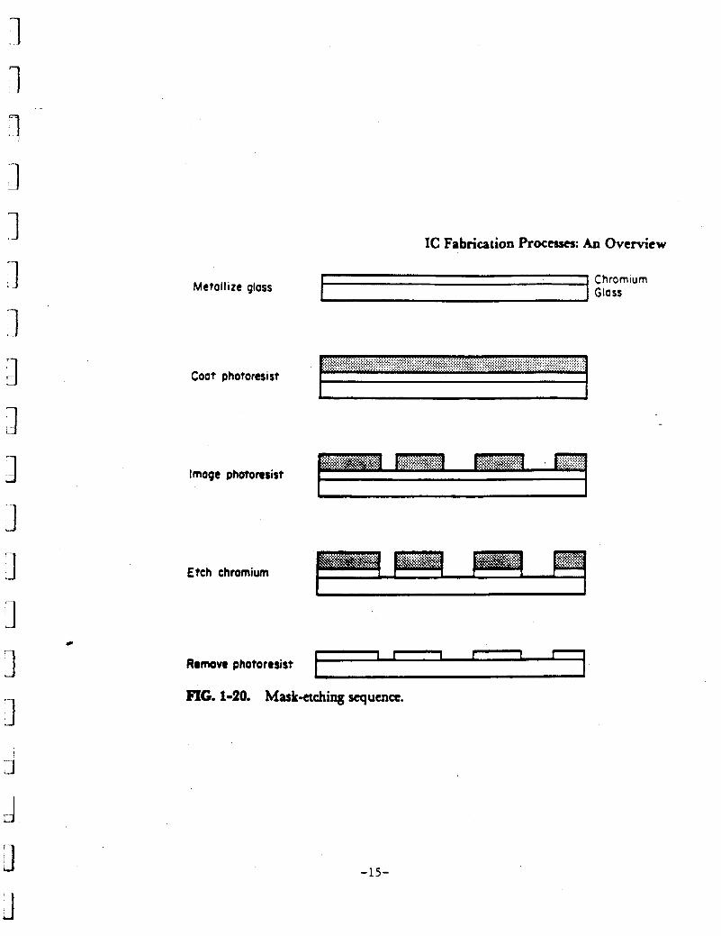
Metallize glass
IC Fabrication Processes: An Overview
Coat photoresist
Image photoresist
Etch chromium ..,. . . . .
c
Remove photoresist
FIG. 1-20. Masketching sequence.
-15-
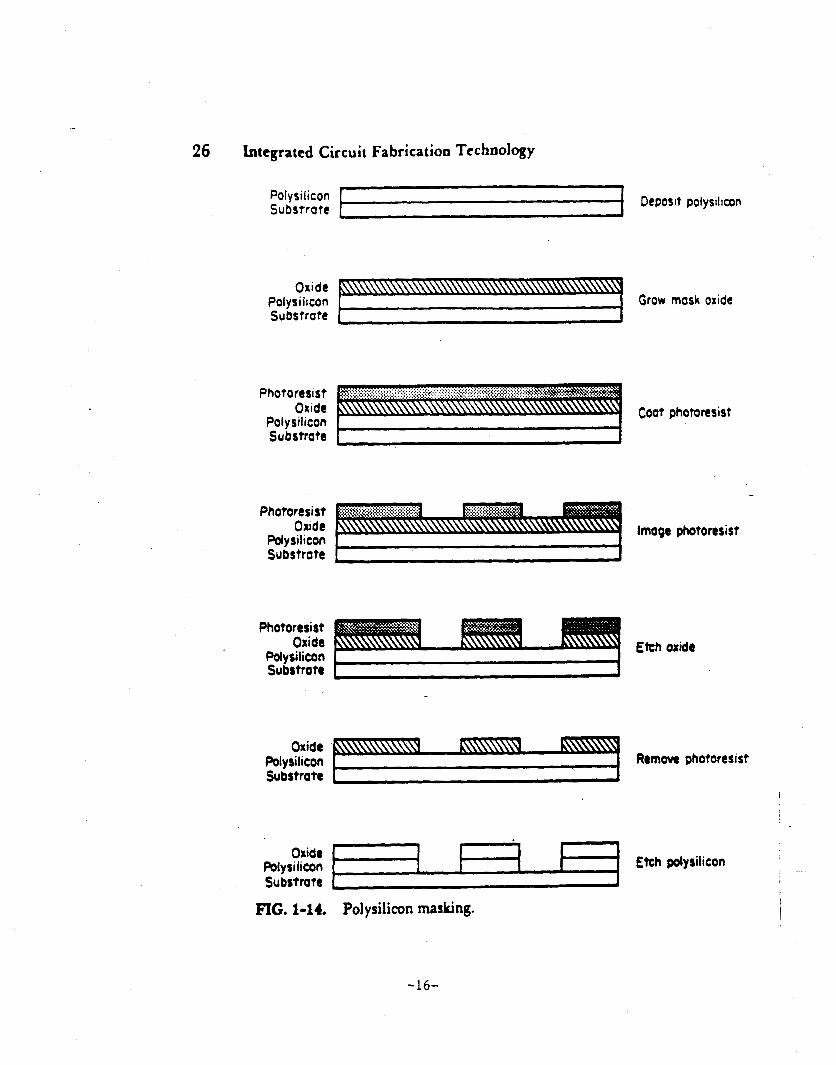
26 bttgrated Circuit Fabrication Technology
Oxide Potysilicon I I I I
Polysilicon Deposit polysilicon Substrate
Etch polysilicon
Oxide Polysilicon Grow mask oxide Substrate [ I
Photoresist Oxide Coat photoresist
Polysilicon Ill Substrate
Photoresist Oudt lmoqa photoresist
Polysi”con Substrote = Photoresist
Oxide Etch oxide
Pdyrilicon Substro te h
Remove photoresist Oxide
Polysilicon Substrate 1 I
Substrate 1 I I
I FIG. 1-14. Polysilicon masking.
-16-
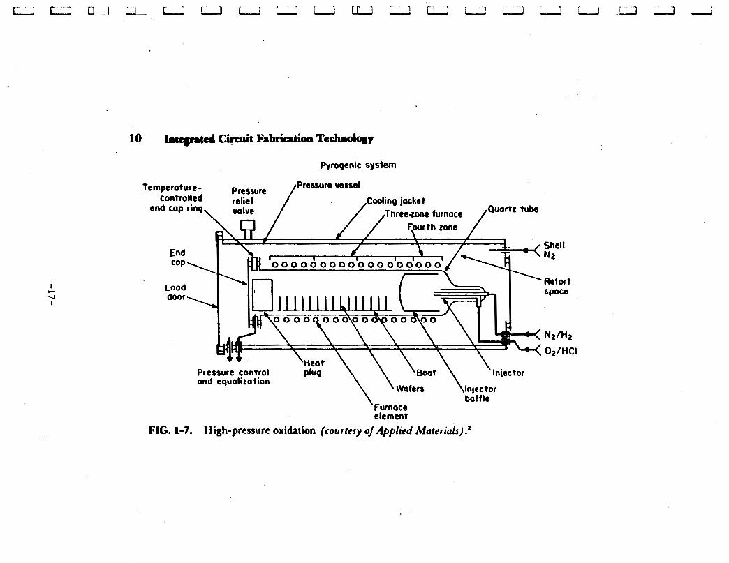
Pyrogenic system
Shell N2
’ Retort space
FIG. 1-7. High-pressure oxidation (courtesy o/ Applied Muferiuls) .2
I
U- Reso
eutral beam and
Terminal F around
‘Acceleration tube
I ‘ J
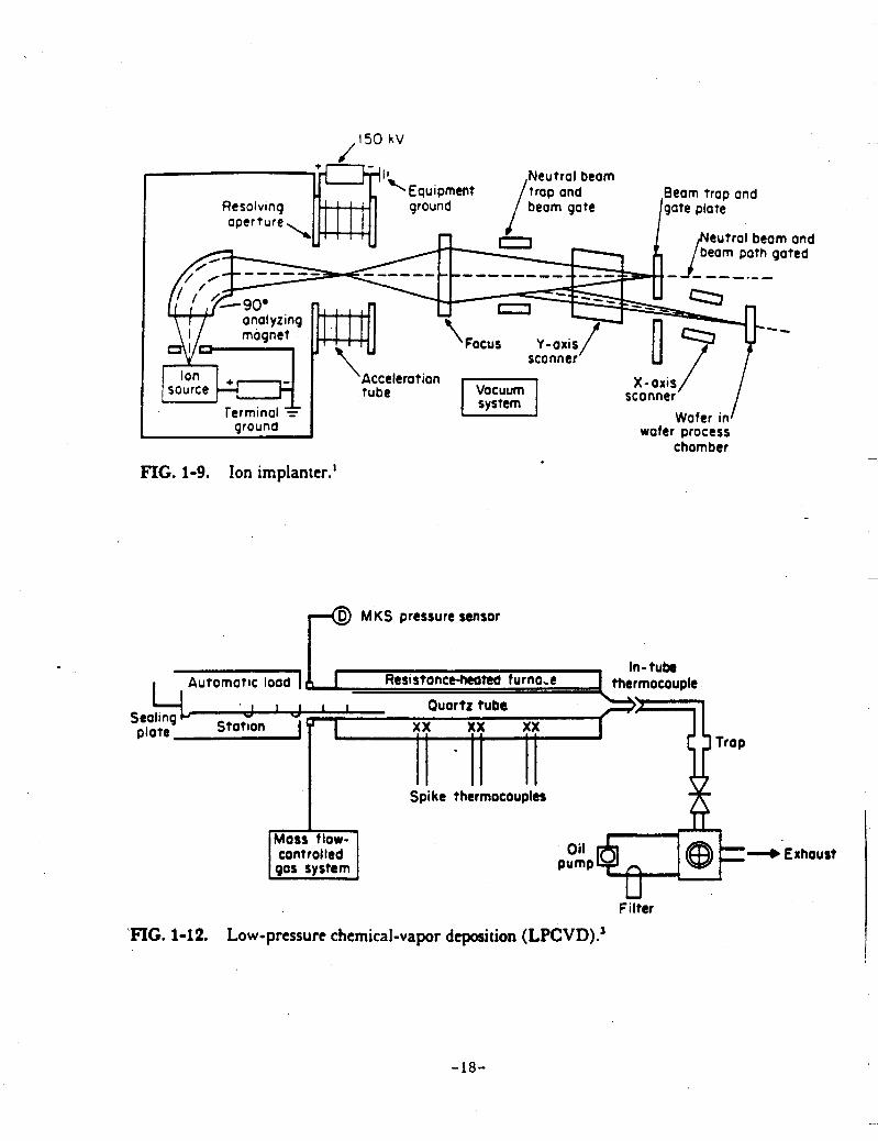
FIG. 1-9. Ion implanter.’
scanner Wafer in
wafer process chamber
4 MKS pressure sensor
In- tube Automatic load 10 I Res1 stonceheated f urna.c thermocouple
I l l - ”
t rap plate Stotion J
Spi kc thermocouples
control led
U Filter
FIG. 1-12. Low-pressure chemical-vapor deposition (LPCVD).’
Exhoust
-18-
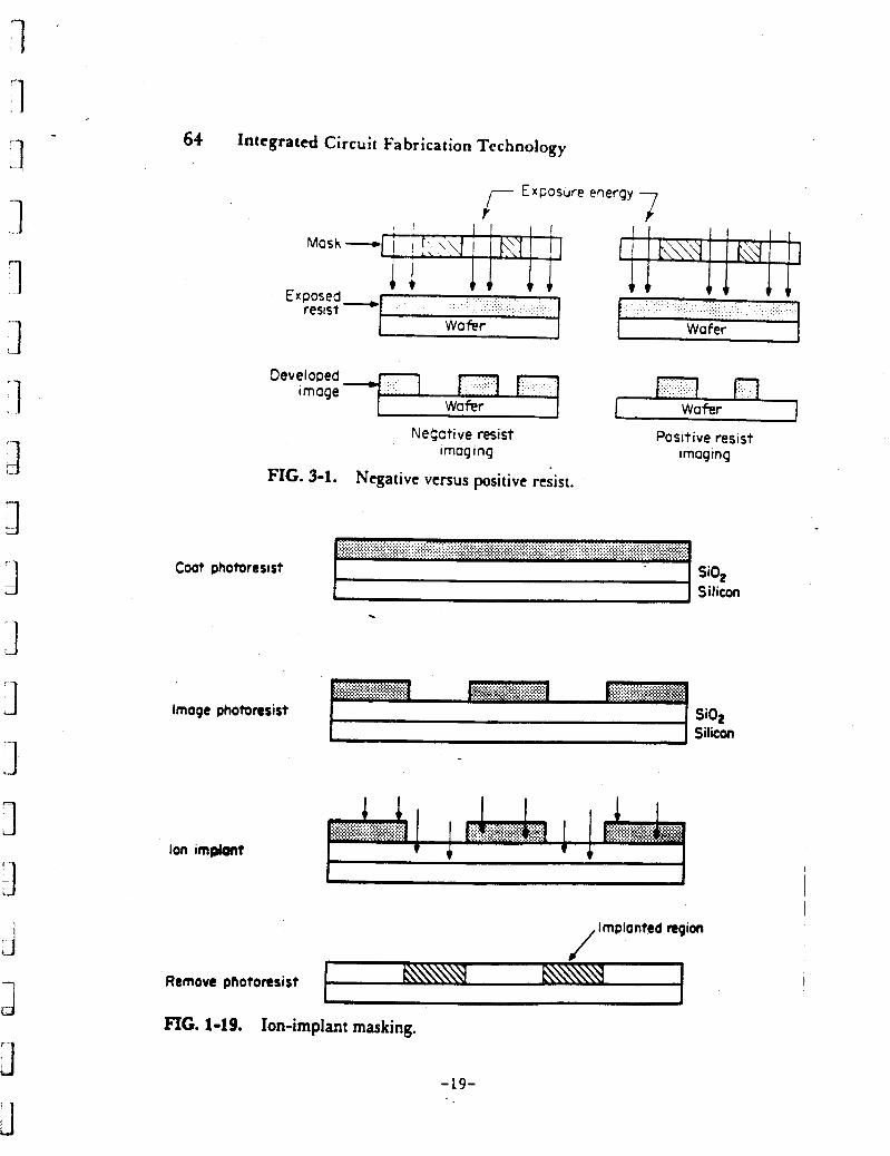
64 Integrated Circuit Fabrication Technology
7 r Exposure energy
Exposed - resist
Wafer
Negative resist I mag I ng
Negative versus positive resist. FIG. 3-1.
Positive resist imaging
Coot photoresist SiO, Silicon .
Image photoresist Si02 Silicon
Ion improlrt I
lmplonted region /
Remove photoresist I FIG. 1-19, Ion-implant masking.
-19-
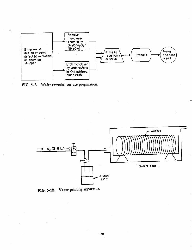
Strip resist due t o imaqinq defect (5) in plasma or chemical stripper
by undercutting
Remove monolayer - chemtcolly
1 Etch monolayer I
$-H-pD or scrub
I I I oxideetch 1 L 1
FIG. 5-7. Wafer reworks: surface preparation.
~
I r Wafers i- I J I
A I \ Wl 1
Ouar tz boat
FIG. 5-12. Vapor priming apparatus.
-20-
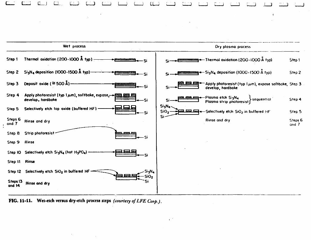
-- - Wet process Dry plosmo process
Step I Therm1 oxidation (200-1000 i typ) -t-dc-si
m- si Step 2 Si,Na deposition (1OOO-1500 i typ)-.-
V- si Step 3 Deposit oxide (I 500 1)
Step 4 Apply photoresist (typ lpm), softbake, expose,d develop, hordboke
Step 5 Selectively etch top oxide (buffered HF) - c- Si
steps Rinse ond dry , ond 7
Step 8 Strip photoresist
Step 9 Rinse
Step 10 Selectively etch Si,N4 (hot H3P04) *E=-=%&; Step I I Rinse
Step (2 Selectively etch SiOz in buffered HF
'3 Rinse ond dry and \4
Si-t-i+Thermal oxidation (200-1000 i typ) Step I
si d ! p - SisN4 deposition (1000 - I500 typ) Step 2
Apply photoresist (typ lpm), expose softboke, Step 3 develop, hard boke
Plosmo etch Si3NN4 sequen tiol s i - - E % T - Plasma strip photoresist Step 4 , - I t S e l e c t i v e l y etch SiOz in buffered tiF Step 5
Uinse ond dry Steps 6 and 7
FIG. 11-11. Wet-etch versus dry-etch process steps (courtesy o j t F E Corp.).
I
Integrated Circuit Fabrication Tcchnolody
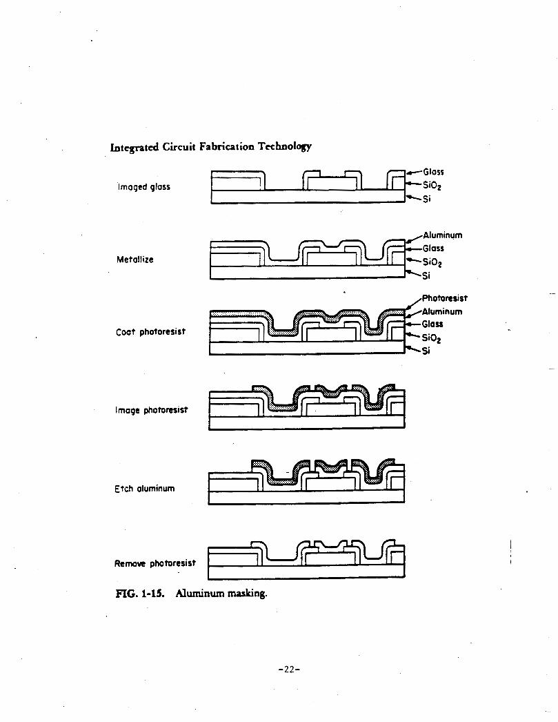
Remove photoresist
Imaged glass
1 ,
Metallize
Coot photoresist
Image photoresist
.Aluminum
.............. L"dl-.-'II ........... , , I
,, E : i n u m ..........
w Si02
1 P\ Si
,-\zp I
::., ....... ....... I
Etch aluminum
I I
FIG. 1-15. Aluminum masking.
-22-
I n 1 3 i.. 1 1 ._ 1 3 3 cd 3 1 3 :I J
1 a il 3
I1 C. Support or Related Processes
PC Board Soldering (Wave and Vapor Phase) 0
0 PC Board Cleaning
0 DI Water Production
0 Wastewater Treatment Operations
PartsCleaning
I1 D. Activity
Objective: .
Develop a prioritized checklist for TURA investigation for either the printed circuit outline or the integrated circuit outline.
Task:
Using two different colored highlighters, color those areas of highest priority yellow and those of secondary priority green. Have your spokesperson ready to give your priorities and the rationale behind each.
-23-
III. Process Characterbation
Objective:
0 Highlight the major considerations and variability in performing "process characteriza- t ion " .
Now that we have completed an overview and initial evaluation of priority areas within these industry segments, it is time to characterize the processes for the purpose of TURA reporting and planning.
Discussion: Recap with the class the definition of the following terms:
0 Production unit
Unit of Product
By-product
0 Emission
BFU
* E R I
-24-
1 n
- 1 1 ‘I 1 .- 1 3 0 J . I 3 11 3 .I
a 3 1
Objective:
To determine what criteria one utilizes in determining the factors for process characterization (Le. production unit (PU), unit of product (UOP), by-product and emissions.
Task:
Divide the class into small groups and have each group determine PUS, UOPs and by-products and emission for either the printed circuit bovd or integrated circuit industry segments. Each group will have a toxics use reduction method assigned to them that will be a component of their 2 and 5 year TUR Plans.
Spokespersons for each group should be prepared to illustrate how their choices for PU and UOP were impacted by the method of toxics use reduction assigned to your group.
-25-
IV. TURA Option “xi Techniques
Objective:
Review TURA Techniques and relate them to options presentlj in use for printed circuit and integrated circuit inanufacturing operations.
Identrfy new and emerging technologies that may be used for TURA in the future. 0
TURA Techniques:
The following list of techniques was developed as part of the Toxics Use Reduction Law for the categorization of pollution prevention methods reported by industry. It is important to understand the interpretation of each of these techniques in order to properly report reductions using the TUR Techniques Matrix.
TUR Techniques Matrix
Vertical Axis
a a a a a 0
0
a a 0
Input Substitution Product Reformulation Production Unit Redesign Production Unit Modernization Improved Operations and Maintenance of Production Recycling or Reuse (closed loop) Miscellaneous
Horizontal Axis
Materials Handling and Storage Process Operations FinishedOoods Handling
-26-

1 7
IV A. Activity
7
1
J I
:I
I*. ‘ 1
Objective:
Test the appropriateness of what participants consider to be TUR options for the printed circuit and integrated circuit industry segments.
Task:
As a class list all the TURA technologies and options you are presently aware of for the printed circuit and integrated circuit manufacturing.
PRINTED CIRCUIT
Task 2:
:.I
INTEGRATED CIRCUT
As a class discuss whether the above options are TUR Techniques and how you would plot them on the TUR Technique Matrix.
a
J -27-
IV B. Printed Circuit Board Options
Substitute aqueous for solvent based resists
Institute a program to manage bath life (temp. increase, min chem adds, testing for contaminants, etc.)
0 Use dry film photoresist instead of wet applications
0 Recycle photoresist stripper solutions
Use of plasma etch instead of wet desmear operations
Use purer anodes and anode bags
0 Increase rinsing efficiency to prolong bath use
Use deionized water for bath makeup
Reduce drag-out (temp., wetting agents, speed)
. Automate plating operations
0 Use mechanical agitation
0 Institute use of water soluble solder flux
Install carbon filtering/carbon treatment
Reuse sulfuric from desmear for WWT
0 Investigate removal of lead from process
0 Spray rinse instead of dip rinse
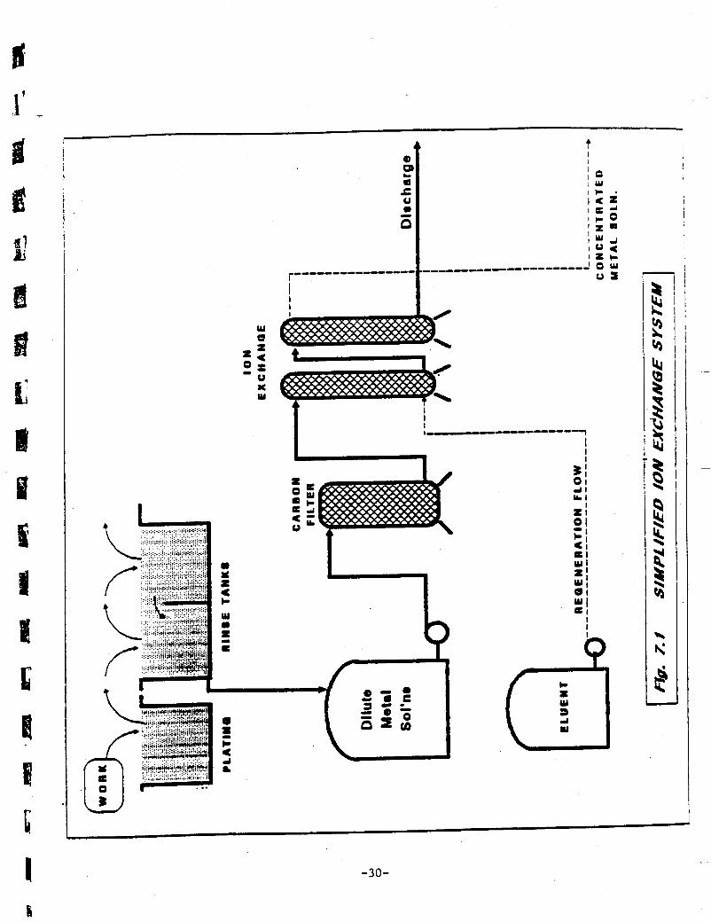
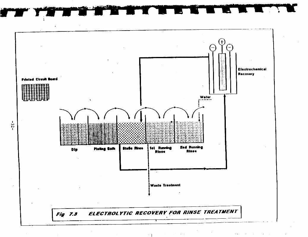
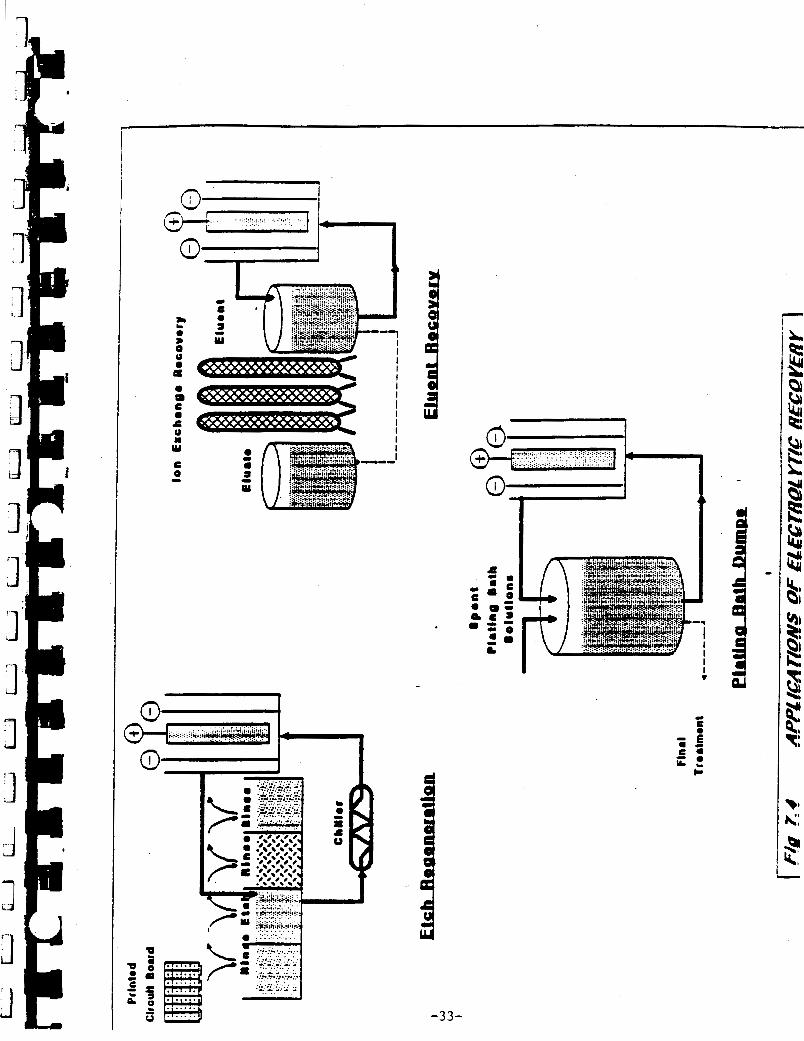
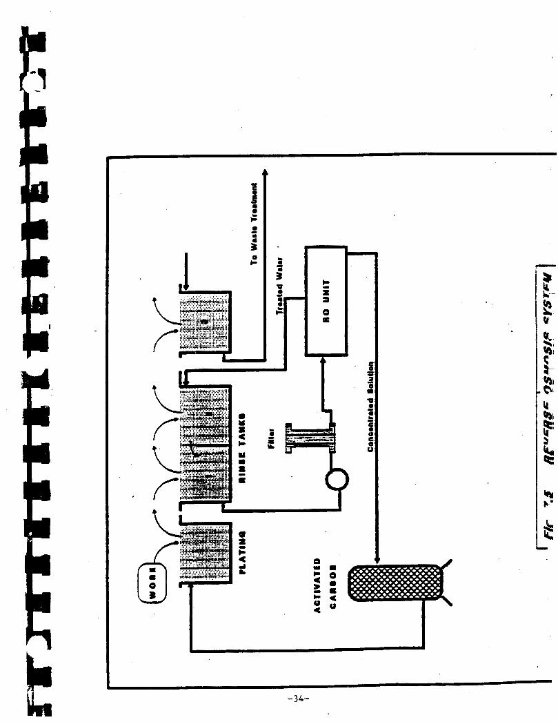
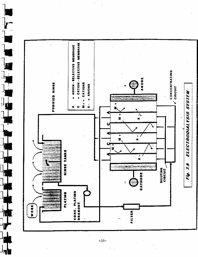
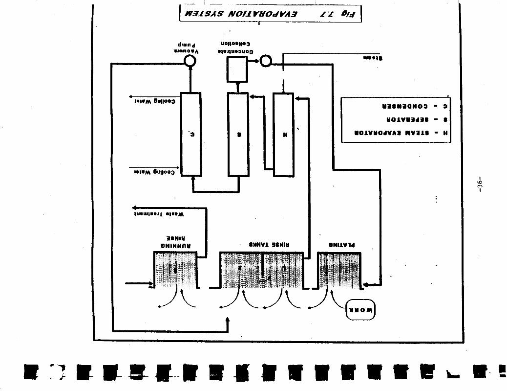
Recover metal value from bath rinses (evaporation, reverse osmosis, liquid membrane, ion exchange, electrolytic or electrodialysis recovery)
0 Use thinner copper foil to clad the laminate boards
Recycle spent etchants (electrolytic diaphragm cell)
Replace solvent based cleaning with altemative cleaning (terpenes, high pressure water, etc.)
Use non-cyanide plating baths
-28-

IV C. Integrated Circuit Fabrication Options
0
0
Substitute cellosolve based resists with "safer" solvent resists
Utilize anhydrous HF cleaning in place of wet RCA cleaning techniques
0 Maximize dry etch versus wet etch operations
0 Utilize new high efficiency tube cleaners
0 Argon flush ion implanters to reduce arsenic buildup for units utilizing arsine
Recycle HF utilizing in-line high purity processing
Eliminate solvent based strippers solutions
0 Utilize high efficiency FSI Units versus chemical bath operations.
-29-
-30-

I
c o 0 - ‘c
- u a 0 !
1 .................................... ................................................. I
I
* .. Q
u 8
-3 1-
I b I' I
*rinlod ClroJI b u d
I Pc ?- . . :. .. . .. . .. . .. .
... ...
-
fiootrochomlcal Rocovory
I I
I I
e 0 C 8
I
f 1
E a a a U a U C I
a a iii
(;i I
:.:- .. I
-33-
7- t I v 1
c) s 0
t c e m - s : I
3 .. I 4
F
c e IL ii
- r
0 a e
t
b ' I I
a s 2
4 4 L
Q Y c 2 0
c 0 4
I I
-34-
1
1-
I
1 : -6
y 7
I
-35-
dwnd wnnowA
7- '3 a
1
H
DNlNNnY I SWNVl 3ENIY
c
*
ONIlV14
Electrochemical
Recovery
Heavy Metal Bnth
1 --
I------ t -'
Solid Metals . @
(ao motat loll:
Chemlcsl Reuse
hemlcd Reure (EIchantt, Coppor B A ~ ) r-----
Dilute Heavy Metala Rlnse8,
Doburr-
Ion Exchange Uncholated /
Chelatod Metal Filter
All othor Rlnres
elc. Fumo Scrubboi
1Scrubb.r 7
[ Recovery
Heavy Metal Free Solution8
f 3 Carbon
hdoorbllon
\ 1
Filter I I
F iltrale 1
f.;\ Water
Ion Exchange Anion / Cation
Pumice Filter Solids
Heavy Metal Free Salt.
a Strlpper Solution8
Sop at ation
Drv Film Sollda
REFERENCES
David J. Elliot, Integrated Circuit Technology, Boston, McGraw-Hill, 1982.
Guides to Pollution Prevention, The Printed Circuit Board Manufacturing Industry, (EPA/625/7-90/007). Cincinnati, Ohio: US EPA, 1990.
The Toxics Use Reduction Institute, Curriculum for Toxics Use Reduction Planners, Second Edition, University of Massachusetts at Lowell, 1991.
Robert L. Judd, et al, Waste Reduction Strategies for the Printed Circuit Board Industry, Alternative Technology Section, Department of Health Services and Toxics Recovery Systems International, 1988. -
Toxic Chemical Release Inventory Reporting Package for 1990, (EPA 560/4-9 1-OOl), Office of Toxic Substances, TS-793, Washington, D.C.
38
TURA Documentation Review
The following is a partial listing of documentation that may be available at the site that will provide information or cross checks to information within the TURA Plan.
OSHA Forms and Recwrds:
OSHA 200 - Accident and Injury Log
0 Hazard Communication Standard Records
Written Plan
Chemical Inventory
MSDS File
Employee training Outline
Lab Safety Standard
Chcmicd Hygiene Plan
MSDS File
0 Respirator Program Requirements
Indusmal Hygiene Surveys
Federal and State Envirunmental:
Air Pollution Registration Forms
Material Profiles
Emission estimates
0 Water Pollution Control
NPDES Pennits
Wastewater Discharge Permit
Sewer Connection Permit
Wastewater Monitoring Reports
-39-
Hazardous Waste Management
EPA Generator Registration (LQG, SQG)
Waste profiles on file with hauler
Hazardous Waste Manifests
Waste Storage Inspection Reports
Annual Waste Summary
RCRA Contingency Plan
UST Registrations (and above ground)
Spill Prevention and Control Plan
CERCLA Notification (Sec. 104)
SARA Notification (Sec. 302,3 11)
SARA Reports (Tier and Form R)
Miscellaneous:
Fire Prevention Plan
Emergency Response Plan
Receiving Records
Purchase Records
Material Inventory Records
Production Records
Shipping Records
J. Pointon. 11/91
-40-

TURA M.G.L. c.211
Industry Reporting Requirements
DATE INDUSTRIES CHEMICALS REOUIREMENTS
July 1, 1990 SIC 20-39 SARA TITLE I11 Section 313 List
Form R's TURA Fee
July 1, 1991 SIC 20-39 SARA TITLE I11 Section 313 List*
Form R ' s TURA Fee Supplemental forms A+-
July I, 1992 SIC 10-14 20-39,40, 44-51,72, 73/75/76
SARA TITLE I11 Section 313 List* 35% C E R C ~ List
Form R ' s TURA Fee Supplemental forms A+
July 1, 1993 S I C 10-14 . 20-39,40, 44051~72, 73,75,76
SARA TITLE I11 Section 313 List* 70% CERCLA List
Form R's TURA Fee Supplemental forms A+
July 1, 1994 SIC 10-14 20-39,40, 44051~72 , 73,75,76
SARA TITLE I11 Section 313 List* CERCLA List
Form R ' s TURA Fee Supplemental forms A+
TUR Plan Summaries
* Thresholds for reporting differ- from SARA TITLE I11 requirements. If yc Manufacture or Process 1 listed chemical in amounts greater than 25,000 lbs, or Otherwise U s e 1 listed chemical in amounts greater than 10,000 lbs , the threshold for all other chemicals that you manufacture or proces becomes 10,000 lbs. The thresholds for chemicals that you otherwise use remains at 10,000 lbs.
-41-
SOURCES OF ASSISTANCE .-
For further information about toxic use reduction contact the following groups:
Associated Industries of Massachusetts 441 Stuart Street Boston, MA 021 16 (617) 262-1 180
Contact: Robert R Ruddock
Massachusetts Department of Environmental Protection Bureau of Waste Prevention one winter Street Boston, MA 02108 (617) 292-5870
Contact: Suzi Peck, Walter Hope
Office of Technical Assistance 100 Cambridge Street Boston, MA 02202 (617) 727-3260
Contact: Tim Greincr ("UR Engineer), Mitch Kennedy (TUR Engineer), Joe Paluzzi O l R Engineer), Barbara Kelley (Director), Rick Reibstcin (SQGs)
US. EPA - Region I One Congress S a e t Bo" MA 02109 (617) 565-1 155
Contact: A b b y S W e
U.S. EPA -
olcfice of Pollution Prevention ~
Mail code PM 219 401 M Street, SW
(202) 382-4332 waSbingtm,Dc20460
ADDITIONAL SOURCES OF ASSISTANCE Specialty trade associations, professional societies, university engineering departments, chemical vendors, and firms offering hamdous waste disposal services may also be a source of free or inexpensive technical assistance. For comprehensive or extensive technical assistance, however, f m s may need to employ the seMces of consulting engineers.
"r
-42-
n ELECTRONICS INDUSTRY MODULE
TUR Planner Certification Course
n I.. -I
3 n 3
Suggested Readings
A. Toxic Use Reduction Efforts at Menimack Valley Works - SSA JOURNAL, September, 1991.
B. The Environmental Impacts of Alternatives to Ozone Depleting Solvents - Raytheon Company, Lexington, Massachusetts.
C. Considerations In The Use of Terpenes For Electrenic Assembly Cleaning - SSA JOURNAL, September, 1991.
D. CFC Reduction Strategies For Industry - SSA JOURNAL, September, 1991.
E. Design For Environment: A Tool Whose Time Has Come - SSA JOURNAL, September, 199 1.
3
-43-

Toxic Use Reduction Efforts at Merrimack Valley Works
Date Dec 1987 Dec 1989 Dec 1990 # Facilities 56 34 B
41 24 24 6
l #Operations I #Chemicals 9 6
q c- 1 From left to
lip&, R.K Gniio, A.M. Veneffa Richard G. Twinine G.P.
right: R.V. Col-
Introduction The purpose of this paper is to il-
lustrate some of the ways that the AT&T Merrimack Valley Works manufactur- ing plant is reducing or eliminating the use of toxic chemicals. The methods in- clude:
0 Consolidation; 0 Conservation; 0 Elimination; 0 Substitution; and 0 Processchangea
Overview of Memimack Valley Works
Merrimack Valley Works is located in N. Andover, Massachusetts, and is the largest manufacturing plant within AT&T. The plant employs a p proximately 6,000 people and encom- passes two million square feet. The plant is actually two factories under one roof. The Transmission Equipment factory manufactures channel banks (D4), mul- tiplexers (DDM-1000), cross connects (DACS), and lightwave regenerators (FT-G).
The Transmission and Switching Com- ponents facto;-./ manufactures printed wiring boards, thin film, thick film, and surface mount technology. All of the products manufactured at Mcrrimack Valley Works are used not only in our equipment production, but are sold to other AT&T locations and companies other than AT&T.
Main Forces Driving the Reduction of CFCs and CHCs
Currently, the main forces driving the reduction of CFCs and CHCs are out- lined below:
0 Management Commitment - AT&T publicly stated that there will be no CFC usage by the end of 1994. Merrimack Valley’s goal is no CFC usage by the end of 1993;
0 MontrealProtocol; 0 Toxic Use Reduction Law, 0 EPA - SARA Sedon 313,
0 Increasing Cost - Taxw have been placed on materials wing CFCs and CHG.
EPA - Clean Air Act; and
The goal of reducing CFCs and CHCs is a challenge to electronics manufactur- ing firms such as Merrimack Valley Works since large amounts are used in degreasing, defluxing and thin film cir- cuit processing operations.
Discussion of Reduction Efforts Consolidation
By consolidation, we mean reducing the number of facilities, the number of operations, and the number of chemi- cals. Table 1 exemplifies the consolida- tion efforts for the years 1987,1989, and 1990. Conservation
Examples of conservation efforts at Merrimack Vdey Works include sol- vent reamcry utilizing charcoalcapture and the solvent recovcry stills for methyl chloroform utilidng distillation. Bulk storage tanks far 1,lJ-trichloroethane and methylene chloride are also used, which is another example of consem- tion.
~
Elimination Eliminatiom n the method of choice
for total reduction of CFCs and CHCs because you arc removing non-value
Table 1 Consolidation of Facilities-Components
Table 2 Chemical Elimination
Rsrerr NewTechniqUC Flhniartt,
Wave Wering LowsolidrPlur TCE, FrcanTHC IPA, Detergents TCE, Frroa,mC IPA, Detcmnts Wave Sddenng
Surface Mount Soldering H20 paste T c r p d
Prr~a TA, I W q C n Pc&& HIC Clunlng
Synthetic nux
N-Doped Plums Etch P W B Gold Rnger Q u n Tap 1.1.1-m
21 SSA JOURNAL September 1991
I
I
J t
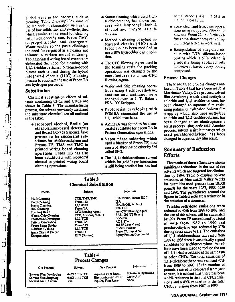
added steps in the proccss, such as cicaning. Tablc 2 excmphfics some of {hc methods of elimination such as the usc of low solids flux and synthetic flw, which eliminates the need for cleaning with trichlorocrhylene, Freon TMC, isopropyl alcohol and detergents. Water-soluble solder paste eliminates the nced for terpineol as a cleaner and thinner in surface mount soldering. Taping printed wiring board connectors eliminated the need for cleaning with l,l,l-trichloroethane. Nitrogen-doped plasma etch is used during the hybrid integrated circuit (HIC) cleaning process to eliminate the usc of Freon TA and hydrogen peroxide. Substitution
Chemical substitution efforts of sol- vents containing CFCs and CHCs are shown in Table 3. The manufacturing process, the solvent previously used, and the substitute chemical are all outlined in the table.
0 Isopropyl alcohol, Brulin (an ethanolamine-based detergent) and Bioact EC-7(a terpene), have proven to be successful sub- stitutes for trichloroethylene and Freons TF, TMS and TMC in printed wiring board cleaning operations. Freon 1l3 has also been substituted with isopropyl alcohol in printed wiring board cleaning operations.
Stamp cleaning, which uscd l,l,l- trichloroethane, has shown suc- cess w i t h isopropyl alcohol, ethanol and m-pyrol as sub- stitutes.
0 Method 6 cleaning of hybrid in- tegrated circuits (HICs) with Freon TA has been modified to use a 10% hydrochloric acid solu- tion.
0 The CFC Blowing Agent used in the foaming resin for packing operations was changed by the manufacturer to a non-CFC Blowing Agent.
0 Wafer and chip clcaning opera- tions using trichloroethylene, acetone and methanol were changed over to J. T. Baker’s PRS-1000 Stripper.
0 Photoresist developing with PGMEA eliminated the use of l,l,l-trichloroethane.
0 AZ1112A was found to be a suc- cessful substitute for Freon TA in Pattern Generation operations.
0 Vapor phase soldering which used a blanket of Freon TF, now uses a pcrfluorinated ether by 3M
0 The 1,l.l-trichloroethane solvent vehicle for goldfinger lubrication is still being studied but has had
called SF-2
Table 3 Chemical Substi tu tion
P n r u t Sdvcnt Substitute
PWB Ckaning PWB Cleaning Stamp Cleaning HIC awing Foaming Ruin Wafer, chip aw- Photoresist Develop Pattem G e n e n t h Vapor Phov Solder Lubricant Vehicle Spray Clean 8 Frceze Encapsulatioa
IPA B ~ t i n . Biora EC-7
sonic succcss wi th PGME or ethanol subsiitutcs.
0 Spray clcan and l r cc l c lest opera- tions using spray cans of Freon 12, now use Frcon 22 and further ef- forts have shown spray cans of liq- uid nitrogen to also work well.
0 Encapsulation of integrated cir- cuits with RTV silicone-based coating which is 50% xylene, is gradually being replaced with non-solvent based epoxy potting compound.
Process Changes There are three process changes out-
lined in Table 4 that have been made at Merrimack Valley. One process, solvent fh developing which used methylene chloride and l,l,l-trichloroethane, has been changed to aqueous film resist, using potassium hydroxide. Solvent film stripping which also used methylene chloride and l,l,l-trichloroethane, has been changed to an electrophoretic resist process using lactic acid. Another process, solvent assist lamination which used perchloroethylene, has been changed to aqueous dry film re$&.
Summary of Reduction Efforts
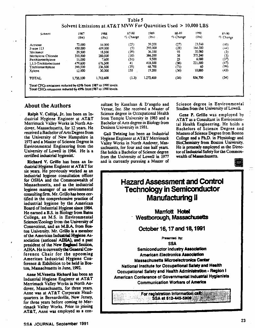
The results of thesc efforts have shown significant reductions in the use of the solvents which are targeted for elimina- tion by 1994. Tabk 5 displays solvent emissions at M c h c k Valley Works for quantities used greater than 10,ooO pounds for the years 1987,1988,1989 and 1990. The parentheses around the figures in Table 5 indkate a reduction in the emission of a chemical.
Trichloroethylene emissions were reduced by 40% from 1987 to 1988, and the use of this solvent wiU be eliminated by 1991. FreonTFwas reduced by a total of 44% from 1987 to 1990 and percloroethykne was reduced by 37% during those same prs . The emissionc of l,l,~-trichlorocthane increased from 1981 to 1088 since it was i5itialty a good substitute for trichloroethylene, but tf- forts have been made to reduce the use of l,l,l-trichlorocthane at the same rate as other CHCS. The total emissions of 1,1,1-trichlorwthane ,was reduced 47% from 1989 to 1990. If the number of pounds emitted is compared from yeat to year, it is evident that there has been a 62% reduction in the total CFCs en&- sions and a 49% reduction in the totd CHCs emissions from 1987 to 1990.
’
93 SSA JOURNAL September 1991
Solvent
I
Acetone Freon I 13 Methanol Methylene Chlondc Perchloroethylene 1.1.1-Trichloroe~hane Trichloroethylene Xylene
Table 5 Solvent Emissions at ATBiT hlVW For Quaqtities Used > 10.000 LBS
n.m 43o.m 29500
310,333 11.000
479.600 390500 12.000
41.ooo 509,000
18500 280500
7,600 676500 236500 30.000
39,200 295,000 36, loo
386,200 9500
418500 68.700 19,200
TOTAL 1,735,100 1,712,600 (1.3) 1,272,400
Total CFCs emissions reduced by 62% from 1987 to 1990 levels. Total CHCs emissions reduced by49% from1987 IO 1990 levels.
About the Authors Ralph V. Collipi, Jr. has been an In-
dustrial Hygiene Engineer at AT&T Merrimack Valley Works in North An- dover, Massachusetts, for 12 years. He received a Bachelor of Arts Degree from the University of New Hampshire in 1975 and a Master of Science Degree in Environmental Engineering from the University of Lowell in 1984. He is a certified industrial hygienist;
Richard V. Grillo has been an In- dustrial Hygiene Engineer at AT&T for six years. He previously worked as an industrial hygiene consultation offcer for OSHA and the Commonwealth of Massachusetts, and as the industrial hygiene manager of an environmental consultingfm. Mr. Grillohas been cer- tified in the comprehensive pradia of industrial hygiene by the Amencan Board of Industrial Hygiene since 1984. He earned a B.S. in Biology from Bates College, an M.S. in Environmental SciencJZoology from the University of Connscticut, and an M.BA. from Bos- ton University. Mr. Grillo is a member of the American Indwrt l Hysiene As-
president of the New Engbd Section, AIHA. He is currently tbe Gcneral Con- ference Chair for the upcoming American Industrial Hygiene Con- ference & Exhibition to be held En Bos- ton, Massachusetts in June, 1992.
Anne M.Venctta Richard has been an Industrial Hygiene Engineer at AT&T Memmack Valley Works in North An- dover, Massachusetts, for three years. Anne was at AT&" Corporate Head- quarters in Bernardsville, New Jersey, for three years before coming to Mer- rimack Valley Works. Prior to joining AT&T, Anne was employed as a con-
4 sociation (national AIHA), and a past
sultant by Kaselaan & D'angelo and Versar, Inc. She received a Master of Science degree in Occupational Health from Temple University in 1985 and a Bachelor of Arts degree in Biology from Denison University in 1981.
Gail Twining has been an Industrial Hygiene Engineer at AT&" Merrimack Valley Works in North Andover, Mas- sachusetts, for four and one half years. She holds a Bachelor of Science degree from the University of Lowell in 1977 and is currently pursuing a Master of
Science degree in Environmental Studies from the University of Lowell.
Gene P. Grillo was employed by AT&T as a Consultant in Environmen- tal Health Engineering. He holds a Bachelors of Science Degree and Masters of Science Degree from Boston College and a Ph.D. in Physiology and Bidhemistry from Boston University.
tor of Industrial Safety for the Commoa- He is preSentty mployed a~ the Dkc-
wealth of Massachusetts.
Hazard Assessment and Control Technology in Semiconductor
Manufacturing II Marriott Hatel
- Westborough,
October 16,17 and 18,1991 Prrsentod by
SSA Semiconductor lndustty Auodrtkn American Electronics A"
Massachusetts Microetlectronb Cantu National Insttitute for Occuprtlonrl S f d y a d Health
Occupational Safety and Health Adminittntim - Region I American Conference of Govemmentrl lnduslrl8l Hygionlrtr
Communication Workem of Amrricr
SSA d 51244s
SSA JOURNAL September 1991 23

1‘ n 3 1 1 II 0 :1 3
THE ENVIRONMENTAL IMPACTS OF ALTERNATIVES TO OZONE DEPLETING SOLVENTS
Raytheon Company Lex i n g t o n, Massa c h use t t s
ABSTRACT The environmental impacts of alternatives to ozone depleting solvent cleaners were
examined in this investigation. The focus of the program was to identify alternative cleaners without ozone depleting potential that would meet Raytheon’s needs for the cleaning of Circuit Card Assemblies (CCA’s). Technologies evaluated were saponified aqueous cleaning systems and semi-aqueous cleaning systems. Rinsewater samples from the two referenced technologies were sampled and analyzed for a variety of parameters including BOD, COD, pH, oil & grease, flashpoint, and heavy metals. Analytical testing of the rinsewaters determined that in both technologies the rinsewaters require treatment prior to disp xal.
INTRODUCTION In response to increasing evidence of the depletion of the ozone layer by solvent
cleaning chemicals and the large volumes of these solvents that Raytheon uses, a task force was created to evaluate effective alternatives to ozone depleting solvent cleaners. The initiative is called The Alternate Cleaning Technology Committee or ACT and was formed in May 1990 by the Raytheon Executive Office of Manufacturing and Environmental Quality. The committee consists of representatives from 15 Raytheon facilities, thus forming a company-- wide, multi-divisional initiative with thirty-five members. The objective of the ACT Initiative is to eliminate ozone depleting solvents, Freon 113, and 1,1,1 Trichloroethane for the cleaning of Circuit Card Assemblies (CCA’s) by the end of calendar year 1992.
Six main requirements were established by the ACT Committee and were used to determine what alternate cleaners would be viable for consideration in the Act Initiative. The six requirements, aie listed below:
0 Must not degrade reliability 0 Non ozone depleting 0 Environmentally acceptable 0 An effective cleaner 0 Safe alternative 0 Currently available
Using this list of requirements, the ACT group conducted an equipment and chemistry survey throughout the industry to determine what types of alternative cleaners would be evaluated. The next genurt ion of solvent cleaners, or HCFC‘s, were ruled out because of their uncertain regulatory future and ozone depleting potential.
The alternate cleaner could not degrade the reliability of our sophisticated military electronics product line. High levels of cleanliness are required to ensure long term reliability.
The alternate cleaner had to be environmentally acceptable which meant we did not want to solve one environmental problem and create another. Using that reasoning, rinsewaters were sampled during all tests of alternate cleaners to determine the environmental impact those rinsewaters would have on our waste treatment facilities and the environment.
The alternate cleaners had to be an effective cleaner. Here at Raytheon we work under
a variety of military specifications and high levels Of cleanliness are mandatory in order to ensure consistent high quality and reliability.
The alternate cleaners had to be safe for our workers. Corporate Health and Safety was a member of the ACT Committee to evaluate the cleaning chemistries that were identified. These involved the evaluation of potential health impacts of compounds such as glycol ethers and some of the new citrus based compounds in the terpene family. Also considered were the potential flammability issues of the alternatives such as the terpene based cleaners that are combustible liquids. Fire detection and suppression systems were fully evaluated.
The alternate cleaner obviously had to be currently available on the marketplace in sufficient quantities to meet Raytheon’s near-term manufacturing and cleaning needs.
Once the cleaning equipment and cleaning chemistries had been selected by the ACT Committee for consideration, the next phase involved the development of a detailed cleaning process specification which would be used for the evaluation of all the cleaners and chemistries. Included in this evaluation was an environmental test plan and health and safety evaluation of the combinations of cleaner and chemistries.
The goal of the ACT Initiative was to identify an effective alternate cleaning procedure that will meet the near and long-term needs of Raytheon in the cleaning of CCA’s to military specifications. A solution was needed both for in-line and batch type applications. Based on the findings in the ACT Initiative for CCA cleaning, i t is expected that these findings will help to accelerate the phase-out of ozone depleting solvent cleaners in other cleaning applications such as machining, bench top, etc.
EXPERIMENTAL PROCEDURE The first step of the ACT Initiative was to identify the cleaning equipment
manufacturers that would be evaluated in the Phase I program. A total of ten cleaning equipment vendors were identified for the Phase I evaluation. The semi-aqueous cleaning chemistries that were included in the evaluation were the terpene compound EC-7R which is made by Petroferm, Inc., and Axarel-38 which is manufactured by Dupont. The saponified aqueous cleaners were made by Kester, Federated Fry, and Alpha Metals.
The second task of the ACT Initiative was to design and fabricate a test board that would represent the Raytheon product line and provide a viable testing vehicle for the alternate cleaners. The final board design was a mix of plated through hole (PTH) and surface mount technology (SMT), measuring four inches by seven inches in size and consisting of two dif ferent substrates, Epoxy E10 and Polyimide.
The ne%! task was to develop a cleaning process specification which would provide a formidable c l d n g challenge for the alternate cleaners. The challenge would be significantly greater than m y that would be encountered during a production process, which would allow the alternate cleaners to be ranked based on levels of cleanliness. The EPA/IPC/DOD Phase I1 testing protocol was integrated into the specification for reasons of comparison and customer acceptance.
The cleaning baseline against which the alternate cleaner would be referenced was an existing cleaning process which used l ,I*l trichloroethane, followed by a deionized water rinse (2 megohm) and completed with an isopropyl alcohol rinse.
The cleaning process specification involved hand soldering of the SMT devices on-site at the cleaning vendor, followed by a one minute immersion in Kester 185 RMA flux, followed
by wave soldering with preheat topside temperature of 220 degrees Fahrenheit and a wave solder tempcrature of 500 degrees Fahrenheit.
The boards were then allowed to dwell one hour after after which the!: were processed through the cleaning equipment. Thirty boards of each substrate, G-10 a.ld Polyimide, were processed fo r each cleaning evaluation.
Following the cleaning process, 15 boards were visually examined for flux residue and the remaining boards were packaged and returned to Raytheon laboratories for surface insulation resistance (SIR) testing. Each board contained 5 SIR patterns for testing purposes. Upon completion of the SIR testing, a total of 840 components were cut, lifted and the board under the part was visually inspected for residual rosin contamination. Ionic residue was determined with rhe Omegameter and organic residues were identif ied using High Pressure Liquid Chromatography (HPLC).
A Phase I environmental test plan was developed to identify parameters that would be tested in the rinsewaters during the Phase I ACT testing program at the vendor sites. The environmental plan called for taking a representative composite sample of the rinsewaters during cleaning, and testing the rinsewater for the presence of five heavy metals, lead, tin, copper, nickel, and-zinc. In addition, rinsewa ter samples were tested for Biochemical Oxygen Demand (BOD), Chemical Oxygen Demand (COD), total suspended solids, pH, flashpoint, and oil and grease. The samples were taken at the vendor sites throughout the country and express mailed back in coolers to an analytical laboratory in Massachusetts for testing. The- environmental objective of sampling the rinsewaters was two-fold; f irst was to evaluate the quantity and quality of the rinsewaters that would be generated from the cleaning equipment and second to evaluate those rinsewater streams for potential closed-loop processing during installation in the Raytheon facilities. The wide variety of wastewater discharge outlets at Raytheon facilities nationwide necessitated the evaluation of a number of treatment technologies for effective treatment of the rinsewaters. Another key element of environmental information that needed to be gathered during the ACT testing protocol was to perform detailed material balances of all the cleaners used in the alternate cleaning methods and determine their fa te in the form of fugitive air emissions, stack air emissions, wastewater discharges, or off-site shipment as hazardous waste.
RESULTS AND DISCUSSION Of the multiple combinations of cleaning equipment and cleaner chemistries evaluated
in the Phase I ACT Initiative, three of the processes using semi-aqueous cleaning solvents were equal to or better than the 1,l.l Trichloroethane, DI water, IPA rinse baseline. In addition, one saponified aqueous in-line system cleaned effectively in the aqueous mode. The Electronic Controls Design (ECD) 6307/6300 cleaning equipment and Accel's Microcel I1 are viable for batch semi-aqueous cleaning processes. These two machines were used in combination with EC- 7R citrus b u a d cleaner. The ECD system utilizes two dishwasher style units and a n auxiliary circulating oven for drying. The Accel machine incorporates a technology which spins the part to be cleaned about its center of gravity and utilizes centrifical force to remove material from beneath components. This cleaning process is known as spin under immersion.
The Detrex Model SA-20 and Hollis Automation Hydro-Station 332 are viable for in-line processes. The Detrex unit can be utilized either in the aqueous or semi-aqueous mode, however, the machine was evaluated in the semi-aqueous configuration only using Axarel-38. To date, our evaluation has not tested the Detrex machine in the saponified aqueous mode. The Hollis Automation Hydro-Station 332 was used in conjunction with Federated Fry 3555 in the saponified aqueous cleaning mode.
The degree of cleaning was determined to be equipment dependent. This was more evident for saponified aqueous cleaning systems than semi-aqueous systems. Although, all the aqueous chemistries were similar, only the Hollis Automation unit could clean well enough to
fulfill the test requirements.
The environmental findings determined that the rinsewaters from both saponified aqueous and semi-aqueous cleaning processes require treatment prior to discharge. Our results indicated that the BOD, COD, and oil and grease limits of the semi-aqueous cleaners in particular, arc well above the allowable discharge limits in most parts of the country. The in- line rinsewater discharge quantities averaged 2 - 3 gallons per minute for running DI water rinse, while the batch semi-aqueous cleaning processes involved the discharge of between 3 and 15 gallons per batch. The in-line saponified aqueous system which averaged approximately 4 - 5 gallons per minute had a BOD, COD content of 9,295 milligrams per liter (mg/l) and 8,830
milligrams per liter (mg/l) respectively, with an oil and grease content of 419 milligrams per liter (mg/l). Generally, acceptable discharge values for BOD average 250 mg/l, with COD seldom listed as a discharge parameter. Oil and grease acceptable values range between 100 and 150 mg/l. In addition, the pH of the rinsewater from the aqueous treatment system was 10.9 which is slightly above allowable limits of 5.5 - 9.5 pH.
There is a significant difference between the handling of the waste wash sumps for aqueous and semi-aqueous systems. The semi-aqueous cleaning baths are reported to be very resilient and able to assimilate large quantities of rosin based fluxes prior to requiring disposal. A steady state equilibrium is apparently achievable, where drag-out of flux residues equals the volume of flux drag-in. Thus only periodically, approximately once or twice a year, the semi- aqueous cleaning bath is discarded and sent off-site as a hazardous waste fuel supplement. In the case of EC-7R, the purchase price of the material includes the cost of disposal as a hazardous waste. Ultimately, based on volumes generated, the EC-7R may be recycled by a hazardous waste vendor.
In the case of the saponified aqueous cleaning sumps, these sumps are generally discharged every eight to sixteen hours of operation and generally average about lOQ gallons in size. These wash tank dumps from the saponified aqueous systems contain the majority of heavy metals, flux residues, and extremely high pH and BOD/COD values. The need for frequent batch dumps on the saponified aqueous cleaning systems results in the use of high quantities of heated water with saponifier and also a large requirement to treat these wash tank dumps prior to discharge. Historically, the reason for short bath life has been that the surfactants, which are volatile, evaporate over time which lowers cleaning effectiveness.
Based on a matrix evaluation of semi-aqueous versus saponified aqueous cleaning, which included health B safety impacts, environmental impacts, cleaning effectiveness and operating costs, the decision was made to pursue the use of the terpene cleaner EC-7R in the Phase I1 Pilot Facility. The Phase II Pilot Facility, which includes 2 cleaners and 2 closed-loop processors, will be installed in a Raytheon Massachusetts facility for cleaning tests on Raytheon products. Although the Hollis machine cleaned to an acceptable level, i t was not incorporated in the pilot facility due to the presence of glycol ethers in the saponifier, projected higher annual operating costs, as a result of frequent wash tank dumps, and a lower potential to allow closed-loop rinsewater processing.
In the area of closed-loop rinsewater processing, the semi-aqueous systems have been designed to readily separate the cleaner from water thus providing an advantage over saponified aqueous systems. Due to the accelerated nature of Raytheon's Alternate Cleaning Technology Program, the decision to move forward with a semi-aqueous cleaner was made in December of 1990. At that time, the technology to close-loop the Axarel-38 product had not yet been defined by Dupont. On the other hand, the EC-7R cleaning compound had been re- formulated to enhance its separability from water thus providing an apparent advantage for closed-loop rinsewater processing.
The ACT Phase I1 Pilot Test Facility which was installed in May of 1991, in one of Raytheon's Massachusetts facilities, included an ECD batch system and a Detrex SA-20 in-line cleaning system, both of which will use the EC-7R cleaning chemistry. To evaluate the
7 1 3 1 n 1 3 a 3 3 1 3 0 3 3 rJ a J J
- feasibility of closed-loop rinsewater processing, Separatioa Technolc ;ists and Simon-WTS systems were installed in the Pilot Test Facility to evaluate their capabi! Y in close-looping the rinsewater streams from both the batch and in-line cleaning units. The i\ 3wledge gained from evaluating the closed-loop rinsewater processors will also be used t : dentif y appropriate technology that can then be used to polish rinsewaters prior to dischar This Pretreatment will involve removing residuals terpene to low enough concentratic to be suitable for discharge to an on-site industrial waste treatment Plant or a municipal ste treatment plant.
Both closed-loop processors use phase separation by specific grav j, granular activated carbon for trace terpene removal, ion-exchange, particulate filtration a c 3 a heating boost back to rinsewater temperature of approximately 100 degrees Fahrenheit.
The quality of deionized water that is required for rinsing of Raytheon CCA's to meet military specifications, ranges between 0.5 and 2.0 megohm. Therefore, the closed-loop processors need to supply deionized water on a continuous basis within that acceptability range.
During the pilot test running of the closed-loop equipment, four significant items of information are needed:
1. Using the present technologies, costs are a function of the amount of consumable- exchange media (Granular Activated Carbon and Ion-Exchange Resins) that will be used on an annual basis. The life expectancy of the exchange medias is directly proportional to the efficiency
of the phase separator units and inversely proportional to the temperature of the rinsewaters. Initially, rinsewater temperatures will be 120 degrees Fahrenheit, however an effort will be made to lower the temperature to 80 degrees Fahrenheit, which will lower operating costs, reduce terpene air emissions and extend exchange media life.
Definition of Annua 1 ODeration & Maintenance Costs
istics of Closed-LooD Rinsewater Processiqg e . 2. A hydraulic balance needs to be attained between the cleaners and the closed-loop
processor. The feasibility of this balance will be determined during the pilot test.
Due to the lack of a large installed base of closed-loop processors on RMA Flux Svstem
Cleaners, analytical work are accumulating.
will be done on the treated water to determine if any contaminants
In addition, the system will be monitored closely for any signs of microbial growth that necessary, a disinfection/sterilization step may need to be added to the may develop. If
system.
T r e a t m t Effrciencv of the Phase SeDa ratora 4. Depending on the type and quantity of cleaner installations and the facility's capability
to discharge wastewater, i t may be most practical to treat and discharge rinsewaters. An example would be the installation of 2 batch units, which would not justify the need to close-loop rinsewaters. For that application, a reasonable treatment scheme may be to phase separate the rinsewater and then polish with granular activated carbcil prior to discharge. Evaluating the treatment efficiency of the phase separators and granular activated carbon steps will determine the quality of effluent that is achievable.
. .
SUMMARY Results from the Raytheon ACT Initiative Phase 1 indicated that the following 4
- processes, 3 semi-aqueous and one saponified aqueous, cleaned to or better than the TCA/DI water/IPA baseline:
In-Line Detrex SA-20 using Axarel-38
Hollis Hydro-Station 332 using Federated
the Raytheon test board eqial
Fry 3555
Barch ECD 6307/6300 using EC-7R
Accel Microccl I1 using EC-7R
\
Based on a matrix which included health & safety, environmental, cleaning effectiveness and operating costs, the decision was made to pursue the use of EC-7R in the Phase I1 Pilot Test Facility. The facility will include two cleaning systems, namely, the ECD 6307/6300 and the Detrex SA-20 and 2 closed-loop rinsewater processors, one manufactured by Separation Technologists of North Reading, Massachusetts and one unit from Simon-WTS of Santa Clara, California.
Follow-up work also continues with Hollis and Accel. In the case of Hollis, an effort continues to identify a non glycol ether saponifier that will provide effective removal of RMA- flux. Accel’s Microcel I1 is being evaluated for application specific opportunities using EC-7R.
The Phase I1 Pilot Facility was started up in June of 1991 at a Raytheon location in Massachusetts. The process parameters for the effective cleaning of the test baords were reverified, and all Raytheon locations have performed cleaning tests of actual production CCA’s a t the pilot facility. c
The objectives of the Phase I1 pilot testing program and findings to date are shown below.
Process
- Identify bottom-line costs
- Develop and document a cleaning process that routinely meets military specifications
Ensure no reliability concerns exist -
Testha to date a t the pilot facility using a variety of CCA’s from Raytheon product lines has been very successful. Numerous CCA’s, including very complex modules that are significant cleaning challenges, have been successfully cleaned to meet military specifications. Line speeds in the Detrex machine using the test board as a baseline have averaged 5 feet per minute, with the rinsewater temperature a t machine ambient, which averages approximately 95 degrees Fahrenheit, due to the energy addition of high volume pumps. Cleaning of complex CCA’s may require modification of the operating parameters.
Based on operating costs, preliminary calculations rank saponified aqueous cleaning as the most expensive, our 1.1.1 trichlorocthane / deionized water / IPA baseline as the.second most expensive and the semi-aqueous process using EC-’IR, as the least expensive cleaning

process.
3 1 7 1 3
3 3 13 I..
3 3 3 1
1
d
Material compatibility results on saponified aqueous cleaners revealed problems with metals and metal finishes, such as black anodized aluminum. The EC-7R material was found to have similar effects to that of 1,1,1 trichloroethane; namely silicones and low modulus (soft) polyurethanes being the problem areas. The materials compatibility issues wi th the terpenes will be manageable.
Customer .) Gain acceptance of alternate cleaning process
Customer acceptance continues to be the greatest hurdle left in our ACT initiative. Specification incompatibility is the single biggest problem hindering the implementation of the alternate cleaning process. Short of a global solution, locations will need to follow the expensive, time consuming contract modification route. Raytheon continues to explore this issue though a variety of avenues.
Environmental
0 0 0 0
- Closed-loop rinsewater processing Definition of annual operating & maintenance costs Logistics of closed-loop processing *
Potential to accumulate contaminant(s) or organism growth problems Treatment efficiency of phase separators and granular activated carbon systems . Development of a detailed material life-cycle for the terpene cleaner, including
fugitive and stack air emissions as well as wastewater impacts Volume of waste terpene generation ..
The process of close-looping the rinsewaters in the pilot facility has proven to be very successful. The hydraulic balancing and water quality have been totally acceptable to date. The operation of the pilot facility has been in a zero discharge mode from June to September of 1991. All rinsewaters generated from the ECD and Detrex cleaning systems have been effectively treated and returned to the cleaners for reuse. Due to limited loadings of flux and terpene dragout during the duration of the pilot plant operation, we were unable to quantify the life expectancy of the closed-loop rinsewater processors, The units did process over 3500 CCA's without requiring exchange media changes.
Analytical testing of the rinsewaters from the batch and in-line cleaning systems, using Raytheon test boards (4" x 7 9 , revealed lower than anticipated BOD and COD levels. The ECD batch cleaner cambosrte . rinsewater samples averaged less than 300 mg/l of BOD and COD. It is important tonote that the first rinse discharges from the cleaner contain the majority of the contaminants. For example the first rinse (prewash), had a BOD value of 1250 mg/l and a COD of 8600 mg/l, while the composite of all the rinses together had a BOD of 140 mg/l and a COD of 275 mg/l. Each rinse discharge in the ECD is 2.5 gallons, with total rinsewater discharges averaging 10-15 gallons per batch, based on the number of rinses used. This data was from a run of 30 Raytheon test boards, 15 on each of the upper and lower racks.
The in-line Detrex cleaner rinsewater averaged less than 200 mg/l of BOD and COD. These results were produced with the conveyor containing test boards over its entire length. The Detrex unit in the pilot facility contains a pumped sump that has resulted in the accumulation of a supernatant layer of terpene. This separation has lowered the terpene burden on the closed-loop rinsewater processors.
Further testing is scheduled on the rinsewaters using higher loadings of CCA's in each cleaning system, -
Stack sampling has been performed on the Detrex machine and results are pending as of this writing. A definite correlation can be drawn between terpene air emissions and ventilation flows. Proper ventilation control and interlocking can minimize terpene air emissions. Based on results to date, the majority of terpene consumption in an in-line system is via air emissions and not in the form of dragout from the spray-under-immersion cleaning tank. - - Employee exposures to terpene compounds
Effectiveness of fire detection and suppression systems in cleaning systems - Successful saponified aqueous cleaners contain glycol ethers, which are suspected
reproductive toxins and are SARA reportable. Toxicological studies of terpenes have shown minor relevant adverse health effects to date.
During routine cleaning operations, airborne terpene levels in the work area are extremely low, generally less than 1 ppm. Results are pending on exposures that may be encountered using the ECD batch cleaner.
The combustibility concerns of terpenes are manageable with proper machine design. Controls include carbon dioxide fire suppression systems and the use of nitrogen inerting - a tmospheres.
10/1/91
1 n 1 1 0 11 1 ra 3 3 J 3 3 3 1 J a 3 J
Considerations in the Use of Terpenes for Electronic Assembly Cleaning
Richard B. Flegel Motorola Inc.
Abstract Concerns over-stratospheric ozone
depletion and the resulting negative af- fects on our environment have caused considerable interest in alternatives to Chlorofluorocarbons (CFCs) as clean- ing agents. One of the alternatives under evaluation by industrial uscrs is terpene based semi-aqueous solvent. Terpenes have been used as cleaning agents for a number of yean in non- eiectronic applications. Recent work has proven terpenes and terpendsurfac- tant mixtures as effective electronic as- sembly cleaners.
This paper focuses on the materials compatibility, safety, and tolricology of terpenes for electronic assembly clean- ing. The technical aspects of board cleaning are beyond the scope of this paper and have been thoroughly ad- dressed in the literature. The use of terpene cleaners in either a batch or in-line cleaner situation involves the control of air and water emissiOnS, fire hazards and worker exposure. Ex- perience with the effects of terpenes on board assemblies, Wiring harnesses, rinse and exhaust systems, and work place atmosphera is now being ac= cumulated. Because terpene cleaners and cleaner systems arc a major depar- ture from the Freon@ 113 and 1,/1 trichloroethane normally used for electronics cleaning, new approaches are required for the incorporation of terpenes in the electronics assembly process.
Background Discovery of the link between CFCs
and stratospheric ozone depletion by. Dr. Sherwood Rowland at the Univer-
sityof California, irvine, in 1973 initiated a series of events leading up to an inter- national agreement called the Montreal Protocol. The concept of the Protocol was to limit the production and there- fore the subsequent emission of ozone depleting chemicals. The agreement has been amended as recently as June of 1990 in London.
The phase out of CFCs, Halons, and major chlorinated solvents such as chloroform and 1,1,1 trichloroethane has necessitated the investigation of al- ternatives to those materials as cleaning agents of electronic circuitry and metal parts. Even though the Montreal Protocol focuses on the CFC producers, industrial users recognize the need for alternatives well in advance ef the im- posed phase out dates.' Banning the usc of CFC as a non-essenrial propellant in 1978 probably slowed the rate of CFC emissions, but CFC emissions continued to climb following the ban. The Novem- ber 1990 amendments to the Clean Air Act include elimination of the produc- tion of CFCs, halons, carbon tetrachloride, and methyl chloroform by
Investigations into alternatives to CFCs for electronic assembly cleaning began in 1988. A major consideration in afftctingchangcs in the cleaning proctss are military specifications. Participa- tion in the Military Electronics Ttchai- cal Advisory Group (METAG), In- dustry Cooperative for Ozone Layer Protection (ICOLP), EPA/IPC ad hoc Committee on Solvent Cleaning, and DOD Mil Spec u)o(l Committee is necessary to make rbt changes happen in a timely manner. Thesc and other committees are vchides for developing responsible and cffedivc spcQfications and rules.
the year m.
CFC Alternatives The major use and emission of CFCs
in electronics assembly comes from the use of Freon 1l3 in solvent cleaning. Freon 113 emissions make up ap- proximately 95% of the total CFC emis- sions. The remaining 5% of the CFC emissions are from refrigerants, halons in fuced fire extinguishing systems, and
minor amounts of CFCs used as solvents in coatings and adhesives.
CFC emkions result from the use of Freon 113 in open top vapor degreasers and in-line vapor degreasers. Of the total amount of Freon 113 purchased, 15% is returned for recycle and 85% is lost through evaporation from equip. ment, handling, drag-out, leakage, etc. Over the past two years, Freon conser- vation efforts included exhaust modifications, automatic hoists, chemi- cal handling changes, leak detection training, operatioridmaintenance train- ing and improvement of awareness of the solvent loss process.
While thcsc conservation efforts were underway, the process engineering groupswere tasked with finding altema- ti= that were acceptable by both our customers and internal environmental, safety and industrial hygiene groups.
reevaluate many of the manufacturing process steps. In many cases unneccs- sary cleaning steps were eliminated, es- sential cleaning steps were improved and cleanhss testing was improved.
The alternatmJ ' in various stages of evaluation indudc
0 Drop-in replacements for Freon
Noclcanprocesse~ 0 Alternative solvents
Thcse tasks p r d e d an opportunity to
113
Substituting 1,1,1 Trichloroethane (TCA) for Freon 113 was the most ob- vious choice as a dropin replacement TCA was rccognqd immediately as an interim substitute. That position has been con6nncd 9th the EPA planaed phase out ofTCA (See Table 1).
Other drop-in ,=placement solvents, such as HCFCs, am becoming a d - able. Solvents ahibiting characteristia
cleaners typically had problems with availability, toiaty, cost, parts corn- patibility, &contribution to w>bue Or- gan;c (VOC) emissions. Ironi- cally the VOC emission issue is P a - titularly importat in t h ~ Phoenix w- due to inaeuiPg emphasis on reducing the voc VO& are linked *O
similar ewugb to use in existing V a P
increaseJ ground l e d OzOnC an-
27
- Table 1
Good h ~ w s - TC4 N o hardware changes, with minor adjustments of hcaters, controls Reduccd cost
Bad Ncws - TCA Lower Threshold Limit Valuc (TLV), higher toxicity Higher boiling point with the resulting damage to certain heat sensitive com- ponents TCA still has an ozone depletion potential of 0.1 to 0.15 compared to Freon@ 113 at 0.8 More aggressive solvent -- damages certain plastic parts
Lower vapor pressure, less volatile
More aggressive solvent -- better able to remove contamination
centrations. The ground level ozone is a health hazard.
The no-clean processes under evalua- tion are beyond the scope of this paper. The no-clean processes are not entirely without safety, environmental and health concerns. Fluxes, flux carriers, air emissions and process wastes all bear consideration in evaluating the no-clean options.
Alternative solvents include water, ter- penes, and saponifiers. Terpenes are of interest because terpene cleaning is compatible with a wide range of existing fluxes. Both the water and water/ saponifier options had limitations not associated with terpenes.
Toxicology of Terpenes Terpenes are widely used in various
food and cleaning applications. The main component of the cleaner in use is a specific terpene called d-limonene. Other terpenes of toxicological interest include anetr.ole, a - and -pinene and p-cymene, camphene, tcrpholenc, and a -terpineol. For purposes of this report, the following remarks refer to d-limonene (CAS # SW47-5).
D-limonene is appaotd for use in food by the FDA. conccntratl 'ox& in food range from 2,OOO ppm in chewing gum to 30 ppm in carbonated beverages. D-limonene is derived largely from citrus rinds or skins.
The route of exposure is via skin ab- sorbtion, lungs and GI tract. The d- limonene is suspected of being metabo- lized into several derivatives and ex- creted in the urine. (See Table 2)
Work-place Exposure A discussion of work-place exposure
to terpenes should include considerable information from previous reports. The EPA's External Review Draft, Aqueous
and Terpene Cleaning lntrrini Report. Kovcmhcr 15, NO, rcfcrcncc in this papcr lacks information on existing ex- perience with terpcncs in industrial ap- plications. Thc rcport projects thc amount of tcrpenc that will be sub- stitutcd for Freon 113 or m e t h y l chloroform in metal clcaning and printed circuit board cleaning. From that projection, environmental effects are estimated using modclling techni- ques.
The current production/consumption of terpenes is as follows: Annual consumption Source pine
Increase for cleaners9 The above figures indicate that sub-
stitutes for PC (printed circuit) board cleaning and metal cleaning could ac- a u n t for a 1% increase in the use of terpenes. The existing use of up to 193
15710 193 million kg 125 to 161 million kg
1.8 million kg
c i t w 32 million kg 8
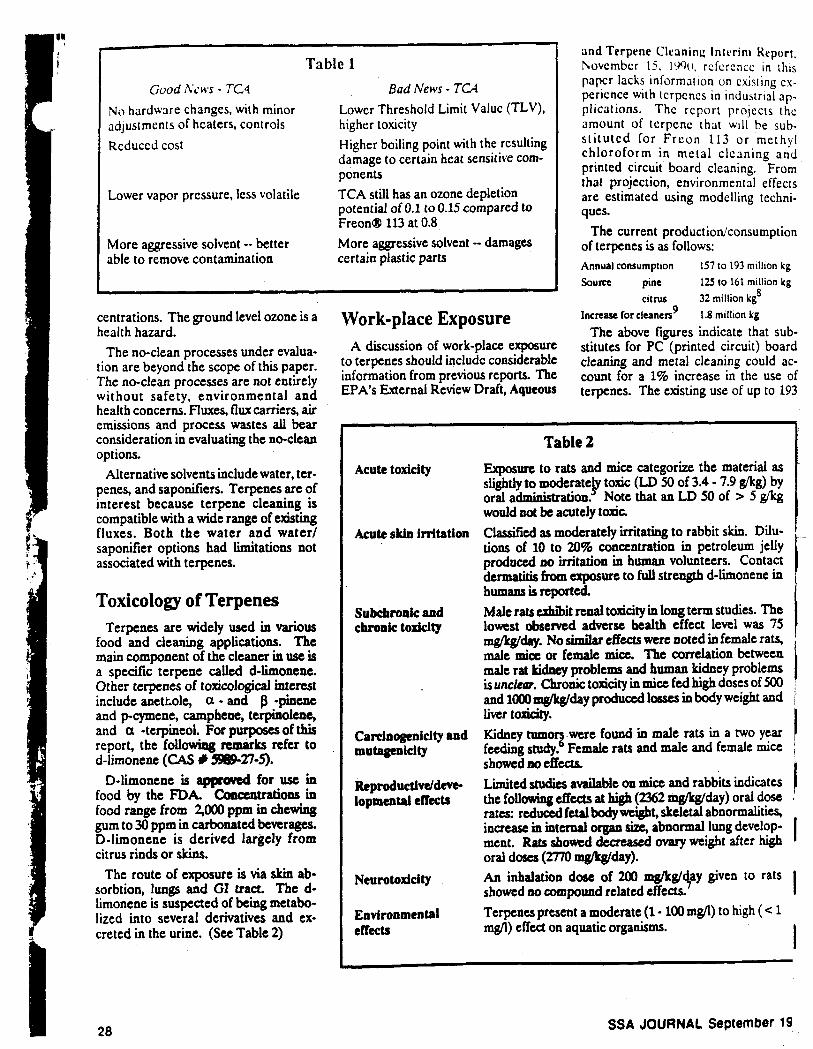
Acute toxicity
Acute skin irritation
Subchronic and chronic toxicity
Carcinogenicity snd mutagenicity
Reproductivc/d~e- lopmental effects
Neurotoxicity
Environmental effects
Table 2
Exposure to rats and mice categorize the material as slightly to moderatep toxic (LD 50 of 3.4 - 7.9 gkg) by oral adminictration. Note that an LD 50 of > 5 g/lcg would not be acutely toxic. Classified as moderately irritating to rabbit skin. Dilu- tions of 10 to 20% concentration in petroleum jelly produced no irritation in human volunteers. Contact dermatitis from exposure to full strength d-limonene in humamis reported. Male rats exhibit renal toxicity in long term studies. The lowest observed adverse health effect level was 75 mgkglday. No dmilnt effects were noted in female rats, male mice or female mice. The correlation between male rat kidney probiems and human kidney problems is unclear. Chronic toxicity in mice fed high doses of 500 and loo0 mg/kg/day produced lossw in body weight and liver toxicity. Kidney tumorg were found in male rats in a two year feeding study. Female rats and d e and female mice s h o d m C f f e d s Limited studies available on mice and rabbits indicates the following effects at high (Z62 +@day) oral dose rates reduced fetalbodywtight, skeletal abnormalities, increase in internal organ size, abnormal lung develop- ment. Rats showed decreased ovary weight after hgh oral doses (2770 mgn%day). An inhalation dose of 200 mg/kg/+y given to rats showed ao compound related effects. Terpenes present a moderate (1 - 100 mgll) to high ( < 1 mg/l) effect on aquatic organisms.
I I I
28
~
SSA JOURNAL September 19
million kg (2I2 .W) tons) IS not discusscd In the EPA rcporl. Thc cnvironmcntal fate dnd i n i p a l of the 1% incrcased tcrpcnc u3ngc I S discussed in detail. With the report having noted the high aquatic toucity of terpenes, thc fate of 99% of the tcrpcne uscd should be of p a t interest to potential terpene users.
The EPA's model for work-place ex- posure takcs into account indoor work- place ventilation and no other control mcasures. For PC board cleaning the estimates are as follows:
Exposure duration e 4 hours Inhalation exposure
terpene 84 muday surfactant 3 mglday
ierpcne 3SM mg/day surfactant 390 mglday
Derma! exposure (ma.)
These estimates do not assume any personal protective measures such as gloves or respirators. Engineering con- trols such as exhaust hoods would also lower the estimated exposure.
Because terpenes remove skin oils and the surfactant component is an irritant, minimal skin contact is expected in the work-place. Gloves and eye protection are the standard recommendation for handling of the d-limonene/surfactant mixture used in PC board cleaning.
Inhalation exposure is controlled with the exhaust systems that are part of the cleaning system design. The con- veyorized in-line system requires 300 CFM of exhaust for the cleaning section of the machine. The rinse and drying section requires ?,OOO CFM for the con- trol of water vapor. The trace levels of terpene odor have elicited reactions from employees that range from - oh, that's a nice smell t o that stink. In general the initial odor is accepted as pleasant. Continued exposure to the odor usually results in the odor be"- ing less and less plcrrmt. Every effort should be made to opente and maintain an effective exhaust system. Another ex- haust consideration is the flammability of the d-limonene. The terpene surfac- tant mixture has an open cup flash point of 63'C and a closed cup flash point of 4TC. Mists produced in spraying sec- tions of the in-line cleaner must be protected with intrinsically safe electri- cal components, f i e suppression sys- tems, and/or inert gas blankets. Scrub bcrs are used to prevent the accumula- tion of terpenes in the exhaust system and minimize the terpene emissions to atmosphere.
In the course of asscmbling infornu- tion for this papcr, I was unahlc to find a n odor threshold value. I suspcct thc vduc is vcry low ( low ppm or cvcn ppb) due to the general ability to detect orurtge peel like odors. The EPA report noted in the bibliography includes a number of references on fragrance and food studies which probably contain such information.
Environmental Release Terpenes are lost from a PC board
cleaning operation via air, drag-out (water), and solid waste.
Batch cleaners using terpcnelsurfac- tant mixtures are expected to release from 450 to 800 k@/unit. Terpenes released to air form smog (via photochemical oxidation) and ozone (via reaction with hydroxyl radicals).
The fate of spent terpenes con- centrates and rinses containing low con- centrations (c 1,OOO ppm) aredepend- ent on the waste characteristics. The spent terpene concentrate can.bc in- cinerated or used for energy recovery provided the metals (lead and tin predominate) concentrations are ac- ceptable to the receiving facility. The concentrate will likely be a Rcsource Conservation and Recovery Act (RCRA) hazardous waste based on lead and/or ignitibility. That wiU necessitate a hazardous waste manifest. Where pretreatment is available, spent terpene meeting discharge limitations can be released to sewer. For discharge to sewer, the main concerns are metals removal and flammability. Closed loop recycling of the water rinse is a realistic option based on energy and water saving. The closed loop system producawaste fiter media, carbon and ion exchange resin. The problems and costs associated with these new waste streams must be considered when evaluating the closed loop option.
Tcrpcncc rclcascd IO the soil rcsdilv adsorb. Acri)bic dccompositlon ratcs are descrihcd a5 slow ( l ak ing wccks for total dccompos r t lon ) . Anaerobic decomposition 15 described 35 vcrv slow with total dccompositlon taking months.
Bench scale activated sludge studies show 90% terpene removal capability. Because aeration is part of the activated sludge process, air stripping (volatilim- tion/evaporation) is suspected as being a significant removal factor. Volatiliza- tion is also the major mechanism for the removal of terpenes from lakes and streams. One model estimates a terpene half life as 5.7 hours in streams and 111 hours in lakes.
The environmental fate of naturally produced and released terpenes was not investigated in the literature. As in the earlier discussion of the EPA report Aqueous and Terpene Cleaning Interim Report, November 15,1990, the environ- mental impact of 99% of commercially produced terpene was not discussed.
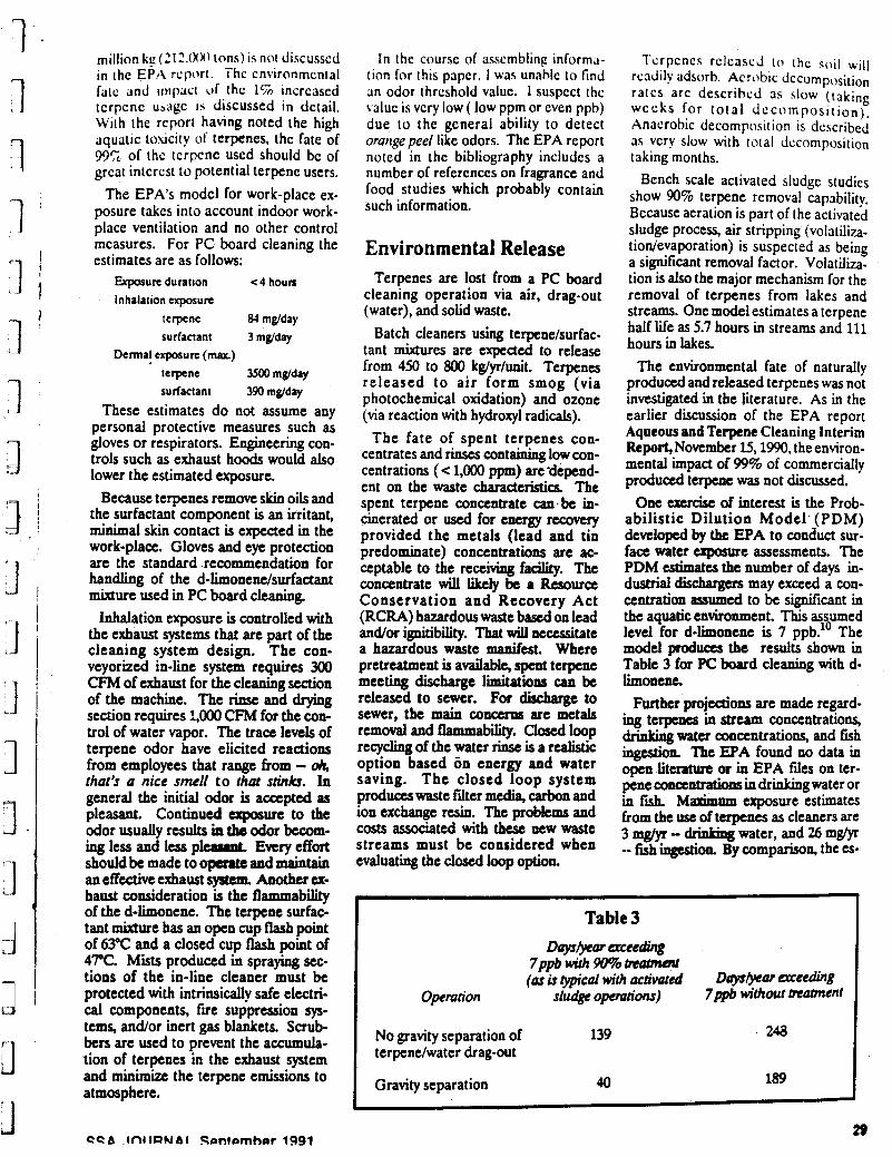
One exercise of interest is the Prob- abilistic Dilution Model (PDM) developed by the EPA to conduct sur- face water exposure assessments. The PDM estimates the number of days in- dustrial dischugus may exceed a con- centration ayumcd to be si@icant in the aquatic environment. This assumed level for d-limonene is 7 ppb." The model produces the results shown in Table 3 for PC board cleaning with d- limonene.
Further projdons are made regard- ing terpenes in stream concentrations, drinking water concentrations, and fish ingestion. The EPA found no data in open literahlre or in EPA files on ter- peneconctntratiooJindrinkingwtcr or in fsh. M a x i " exposure estimates from the use of terpenes as cleaners are 3 mg/yr - drink& water, and 26 mg/yr -- fish ingestion. By comparison, the es-
Table 3 DoysEyar acceding
7ppb with W% ~atment (as is typical with activated D q s w a r a r e e h g
Operation sludge opemtions) 7pM without matment
No gravity separation of 139 terpcne/water drag-out
248
Gravity separation 40 189
29
I
11 limated cxposure 10 aqueous clcancrs via drinking watcr is at 50 mgycar.
Materia Is Compatibility Electronic Parts and Com- ponents
As stated earlier, the technical aspects of cleaning are beyond the scope of this paper. The following discussion is in- tended to give an overview of the problems associatedwhh terpenesb the PC board environment.
For general purposes d-limonene is considered somewhere between Freon 113 and methyl chloroform in aggres- siveness toward plastic parts, com- ponents, adhesives, and coatings The majority of parts that can be successfully processed through an open top or in-line vapor degreaser containing methyl chloroform can be processed using batch or in-line terpene cleaners. The terpene portion of the cleaning opera- tion has no significant heat problems. In fact, the terpene is cooled to prevent frictional heat build-up. A 6YC water rinse step is followed by a 1lOT hot air drying step. These two steps expose the materials to highest temperatures in the cleaning process.
Military applications require boards and components meeting Mil Std 202 F, Method 215 G (Notice lo), for solvent resistance. The solvents used in Mil Spec 202 are: i 1 part IPA 3 parts Mineral Spirits
0 Acetone 0 :,l,l trichloroethane 0 5 parts Freon 113:6 parts
Methylene chloride (Freon
0 1 part butyl ctlloro1ve:l part monoethanolrmine:42 parts water
Methylene chloride in the Freon TMC mixture, in particular, is more aggrcyivt than terpene. Materials passing this specification will most likely be unaf- fected by terpene. The majority of the parts are epoxy and urethane-type plas- tics. Both of these materials are terpene resistant under cleaning conditions but urethanes show degradation with prolonged exposure to d-limonene.
The types of parts affected by terpene exposure include:
0 Parts containing elastomer seals such as BUNA-S, EPDM,
TMC)
Fluorklicone, Fiuoroclastomcr, H Y PALON. Polyacrylate, Polysulfide and Urcthanc are af- tcctcd to 80% swelling) after immersion in 38°C (100°F) d- limonene/surfactant for 14 days.
e Parts containing plastics such as polyethylene (both conventional and linear), polypropylene, polyallomer, polyvinyl chloride, polysulfone, urethanes and polystryrene were found to soften and/or swell after 30 days ex- posure at 20°C.
Parts showing little or no effect in-
0 Elastomers such as BUNA-N, HYCAR, Nitrile, Viton, Tygon were only slightly affected ( c 4% swelling) after immersion in 38°C ( 100°F) d-limonene/surfactant for 14 days.
0 Plastics such as polymethylpen- tene and teflons showed no effect after 30 days exposure at 20°C.
Examples of the part typcs that haw raised concerns for immersion cleaning include trimmer pot en t iomet ers, tunable coils, crystal reference oscil- lators, and power amplifier modules. In some cases, sensitive parts are post in- serted and hand soldered and hand cleaned. In other cases openings in parts are tapedhealed prior to cleaning.
In all cases the supplier of the parts should be consulted for advice and in- formation on the effects of a new dcan- ing process. Cleaning Equipment and Plumbing Materials of Con- struction
Equipment manufacturers have had approximately two years of experience with the handling of terpenes. The scc- tion above lists the plastics and elas- tomers found to be compatible with ter- penes and terpendwater emulsions. It was learned that grey PVC fails in con- tact with a water/terpene mixture (200 to 1,OOO ppm terpene). The PVC plumb- ingfor the rinse water was attacked after two months use. The higher density white PVC was not similarly affected. Plumbing specifications now include stainless steel, PVDF, or Teflon for severe (full strength) applications and Polypropylene for rinse applications.
The metal of preference in these sys- tems is stainless steel. The sumps, plumbing, spray bars, pumps and hoods
clude:
ol the clcanhg machines invcstigaled a r e practically all stainless steel. Bronze, coppcr and galvani7ed stcel are also compatible but less corrosion resis- tant. Stainless is used to eliminate the corrosion problems possible when watcr is introduced to the system. The rinse system of the in-line operation is separate from the cleaner section but cross contamination is always a concern.
Summary Terpene surfactant mixtures are com-
ing into acceptance as PC board cleaners. When bringing these materials into the work-place as replace- ments for Freon 113 and methyl chloroform a number of considerations come into play
0 Combustibilitr. The flash point of the d-limonenehurfactant mix- ture is 117°F (TCC) which clas- silies the material as combustible. The development of mists mixed with air are the main concern. Equipment designs that include inert gas and/or fire suppression
ment should include intrinsically safedesigninthe terpenecontain-
0 Toxic@ The mixtures in use have been found to cause der- matitis, drying of the skin, and lung initatha Contact should be prevented through good en- gineering design of equipment, plumbing aud exhaust. Personal protedivc equipment should be used as in all chemical handling procedures. That includes material specific .impervious gloves, safdty eye-wear, face shields, Ctc
0 En- Aquatic toxicity data precludes the direct dis- charge of terpenes to surface waten. The specific terpene of interest in this paper, d-limonene is biodcpdablc in conventional activated sludge processes and decomposes in soils. Release to air res& in smog and ozone for- mation. The control of air emis- sions is achieved with water scrub- bing.
0 Materials Compatibilitr: Materials of construction for han- dling concentrated mixtures are, for the most part, limited to s t a h less steel, BUNA-N, HYCAR, VITON, Teflon, and Tygon.
systems arc mandatory. €quip
ingsedions.
Rinse waters can bc handlcd by polypropylcne and l inea r polyethylene when temperatures permit. Elcctronic components compatible with immersion in TCA are typically compatible with immersion cleaning in ter- penes. Component cleaning con- siderations mainly involve the rinsinddrying stage. Design of components and assembly proce- dures can accommodate most of the clean/rinse/dry needs. PC boards requiring hand insert, hand solder, hand cleaning in the Frcoo/TCA environment will re- quire the same treatment in the terpene environment.
Acknowledgements The author thanks Motorola col-
leagues Andrew Dobbs, Bradley Lackey and Christine Poupard for their valuable contributions to this paper.
About the Author Richard Flcgel is Manager of Environ-
mental Affairs at Motorola Government Electronics Group in Scottsdale, Arizona. His responsibilities encompass the environmental compliance and en- vironmental risk management activities. He holds a B.S. in Biology from Western Michigan University, and has pursued graduate studies at Illinois Institute of Technology and Arizona State Univer- sity. He has prior experience with cop per foil and water treatment equipment manufacturers.
References FA. Ria , S. KcuMn, 'Substitutes & Altuar-
t i o d SAJ4.P.E Elcamah cmlerrace Proccedinp, pgr 804415 Jum US. EPA, Oftice of Taaic- E x t d
terim Repon", Nov. 15,19#L
t ins to CFC-113 &red -g', 3rd latcmr-
R c v i e ~ Draft, 'AqueoW lT- auning In-
H. P. Liebmm, AB. Suppe&, Terpene Tech- nolw Eliminates CFC Quning of Ekctnmic Assemblies', Motorola Advanced Manufrctur- tng Tcchnolopy Symposium, Oct. 11,1990. G. Attalk. 'Equipment Considerations When Cleaning With Terpene Hydroarbonr', Surface Mount Conference Proceedinfi pp. 499-MJ, 1988 M.E. Hayes, .Hi@ PCrf0"fe Quning with Terpene Surfactant Mixtures', Surface Mwnt Conference Proceedin& pp. 481497,1988.
Foc-notes The l: l ' . \ promulptcd rules unds- !he aulhoniyof the Clean Air Act on BIIZI'M. (53 Fed. Keg. 20566) to implement the provisionsol the Montreal Protc+ol. The 11/90 Clean Air Act amendments tn- cluded a number of prowsions based on the 6/90 modifications to Ihe Montreal P r o t m l (in London). As indicated in the
CFC- -. Much of the literature refers to i , i , i Trichloroethanc as methyl chloroform. Common terminology is TCA or ChlorotheneQP or a ~659. HCFCs arc chlorofluorocarbons with one or more hydrogen a tom in the stme- ture. The hydrogen makes the com- pounds less stable. The result is the more rapid breakdown of the rohrcnt in the larver atmosphere. If animal test data were directly a p plicable to humans. a 420 gram (or SO0 ml.) dose would have a 50/50 chance of being acutely toxic (fatal) to the author, weighing in at 185 pounds. The EPA report referenced in this paper details the male rat tumor devckpmcnt. There appcan to be little correlation be- tween male rat kidney tumor and human
7
8
9
10
11
12
LJrcincpcnictn l l u m a n protclns are dls- himilar to the rdt prtxein involved and as such I I IS unlikely !hat thc h u m a n kidne. could or would develop buch tumor latcd protein. /I commercrlallv avallablc tick'flea dlp for petscontainingd-limonene IS rcponcd 10 have neurolopcal effects. The effects are most likely from the insccttclde com- ponent. but the ingredients were not studied separately. Florida's production of d-limonene is es- timated as 6.8 million &/year. The EPA estimate assumes terpene will substitute for 3% of the Freon 113 and methylchloroform used in printed circuit cleaning and for 10% of the Freon 113 and methyl chloroform used in metal cleaning. 7ppb isbased onacute toxicity data from fish and daphnia. Aqueous clcanen in the report include ammonium hydroxide, EDTA, sodium carbonate, monoethanolamine, TSP, Borax. etc. Polypropylene (PP) is used in applica- tions for rinse w a i e r ~ at temperatures ~ 6 5 ° C . PP is listed by Petrofenn as 'Good' for 30 days exposure to full strength tcrpene/surfactant. Good is defined as little or no effect.
Safety in Numbers t
Semi-Gas Systems has the numbers, in gas application sdutiocS, in satisfied customers. The semiconductor industry's largest povider of gas handling and purification systems.
0 Cylinder Enclosures 0 Auto-Purges Systems
0 Nanochemm Gas Purification 0 Gas Equipment Management System-GEMS?
SEMI 6 GAS 625 Wool Creek Drive. San Jose. CA 95112
(408) 971-6500 (800) 227-7468 S+STEMS INC FAX: (408) 275-8643 J
31
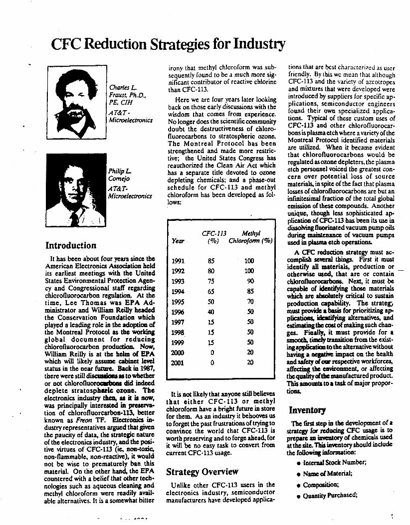
CFC Reduction Strategies for Industry
Charles L. Fraust, Ph.D., PE, CIH
Microelectronics AT&T-
Philip L Comejo
Micr0eleco"cs AT&T-
Introduction It has been about four years since the
American Electronics Assodation held its earliest meetings with the United States Environmental Protection Agen- cy and Congressional staff regarding chlorofluorocarbon regulation. At the time, Lee Thomas was EPA Ad- ministrator and William ReiUy headed the Conservation Foundation which played a leading role in the adoption of the Montreal Protocol as the working global document for reducing chlorofluorocarbon p~oduction. Now, William Reilly is at the helm of EPA which wiU likely assume cabinet Iml status in the near future. Back in 1987, there were st i l l discrppau rstowhether or not chlorofluorocrkrrrr did indeed deplete stratospbsric ozone. The electronics industry then, as it is now, was principally interested in tion of chlorofluorcarbon-ll3, better known as Freon TF. EIectronb in- dustry representatives argued that give0 the paucity of data, the strategic nature of the electronics industry, and the pi- tive virtues of CFC-113 (ie, non-toxic, non-flammable, non-reactivt), it would not be wise to prematurely ban this material. On the other hand, the EPA countered with a belief that other tech- nologies such as aqueous cleaning and methyl chloroform were readily avail- able alternatives. It is a somewhat bitter
irony that mcthyl chloroform was sub- sequently found to be a much more sig- nificant contributor of reactive chlorine than CFC-113.
Here we are four years later looking back on those early discussions with the wisdom that comes from experience. No longer does the scientific community doubt the destructiveness of chloro- fluorocarbons to stratospheric ozone. The Montreal Protocol has been strengthened and made more restric- tive: the United States Congress has reauthorized the Clean Air Act which has a separate title devoted to ozone depleting chemicals; and a phase-out schedule for CFC-113 and methyl chloroform has been developed as fol- lows:
Year
1991 1992 1993 1994 1995 1996 1997 1998 1999 m 2001
CFC-113 Methyl (To) Chiorofom (%)
85 100 80 100 75 90 65 8s 50 70 40 50 15 50 15 50 15 50 0 20 0 20
It is not likely that anyone still believes rat either CFC-113 or methyl lloroform have a bright future in store i t them. As an indusw it behoovts US
to forget the past frustrations of trying to convince the world that CFC-113 is worth preserving and to forge ahead, for it will be no easy task to convert from current CFC-113 usage.
Strategy Overview Unlike other CFC-113 users in the
electronics industry, semiconductor manufacturers have developed applica-
tions that are bcst characteri7ed as user friendly. By this wc mean that although CFC-113 and the variety of azeotropes and mixtures that were developed were introduced by suppliers for specific ap- plications, semiconductor engineers found their own specialized applica- tions. Typical of these custom uses of CFC-113 and other chlorofluorocar- bons is plasma etch where a variety of the Montreal Protocol identified materials are utilized. When it became evident that chlorofluorocarbons would be regulated as ozone depleters, the plasma etch personnel voiced the greatest con- cern over potential loss of source materials, in spite of the fact that plasma losscs of chlorofluorocarbons are but an iafnitesimal fraction of the total global emission of these compounds. Another unique, though less sophisticated ap- plication of CFC-1U has k e n its use in d i d v h g fluorinated vacuum pump oils during maintenance of vacuum pumps used in playrrp etch operations.
A CFC reduction strategy must ac- complish scycfal things, Fitst it must identify all materials, production or ~
otherwise used, that are or contain chlorofluorocarbons. Next, it must be capable of identifying those materials
production capabfity. The strategj must pIcnridc a basis for prioritizing a p plicatioas, identifying altemativw, and
ges. Finally, it must provide for a smooth, titlrcfy tramition from the exist- i n g a p p k a b to the alternative without having a ne@c impact on the health and safety d m respective workforcy affecting the environment, or affecting the quality dthc "facturcd product. This amounts to I task of major propor- tions.
which are ibsolwely aitical to sustain
a t k c w t o f a s u c h c h m -
Inventory The first step in the development of a
stratcgy for dpCiag CFC usage is to prepare an immtory of chemicals used at the site. ?his hentory should include the following idormation:
0 I n t e d stock Number; 0 Name dMaterid; 0 Composition; 0 Quantity Purchased;
0 Quantity On-hand; Quantity Withdrawn; and
0 Uscr Organization.
!'*
This invcnlory becomes the informa- tion sourcc for a facility or company- wide database on chemical usage. When tied to a material ordering database, information on chemical usage can be tracked on a component- by-component basis. Using a system such as described, it is possible to iden- tify and track the CFC components of solvent mixtures, the quantities used, the processes using CFCs, and where the large users are. The system can also be utilized to develop accurate monthly and yearly comparisons of CFC usage.
Support Groups Probably the worst way to approach
transitioning from chlorofluorocarbon use to the next generation of cleaning processes is to allow each user to fend for himself. This only serves to maxi- mize inefficiency and guarantee a multi- tude of partial solutions. Rather than waste a lot of time reinventing the wheel, it is important for indristrial users of CFCs to work together to identify and implement effective alternative tech- nologies. Meetings such as the ones that have been orchestrated by the United States Environmental Protection Agen- cy provide excellent forums through which new ideas and common tech-
important to understand what's happcn- ing outside one's own immediate sphere of influence and how others are a p proaching long-range and short-term solutions. Attendance at these mechgs and active participation should bc en- couraged as M important facet of a CFC control strategy.
Corporations shoutd o m com- mittees or task forms to identify com- mon approaches, mrrirtcnt goals and
tablish realistic time limits for im- plementation of required changes. It is important that someone high in the or- ganizational ladder be identitied as the standard bearer for the issue, someone who can provide effective support that will be viewed as representative of cor- porate interest in the issue.
Formation of and regular participa- tion in local chlorofluorocarbon user committees or groups is of paramount importance to any effective CFC control strategy. It is at this lcvcl that a lot of the
nologies can be openly discussed It is
p o l i c i e s , f u n d i n g ~ ' arrdtocs-
r e d work will be accomplished. Like I hc Corporate committcc, this group must have the support of thc top local management. Key members of the coiii- mitlee would bc as follows:
0 Purchasing Agcnts; 0 Process Engineers using CFCs; 0 Product Engineers; 0 Maintenance Engineers; 0 Plant Engineers; 0 Environmental Engineers; and 0 Industrial Hygienists.
The charge of this group should be as
0 Identify materials used which
0 Identify processes using CFCs; 0 Quantify CFC usage by material; 0 Identify unique, critical applica-
0 Prioritize CFC applications; 0 Develop local CFC reduction
0 Implement CFC reduction
follows:
contain CFCs;
tions;
strategy, and
strategy.
Conservation Techniques It is important to note that the
phaseout schedule shown earlier in this presentation represents national tar- gets, not necessarily targets to be achieved by individual users. It is likely however that CFC suppliers (in a short supply environment) 'will continue to provide these materiais to corporations in a manner which is consistent with the phaseout schedule and proportional to documented use. However, the cost of using these materials will continue to rise. Already we've seen the base cost
additional excise tax of Sl.lO/Ib im- posed. This tax d a t e s with time to a maximum tax of S3.92flb by 1999, the year prior to total phaseout. What this all means is that although CFCs will still be available during this decade, their continued use will become exceedingly CxpcnJiW. To wait around in hopes of some new,
inexpensive drop-in replacement for CFC-113 while the cost of using eXkt;lg supplies spirals upward is not a par- ticularly productive way to deal with the problem. Rather, if it's not already being undertaken, a better strategy would be
Of CFC-113 double to large and an
(0 implcmcnt and cnforcc J< FC c,,n.\cr- vation program. Thrs program should bc two-pronged. First, attcniion must be paid to bhclher o r not a CFC is rc- q u i d for a particuhr application. I f critical applications for which no sub- stitute currently exists arc identified, at- tention should be directcd towards in- suring that usage is kept to the lowest achievable levels.
The first tenet should be rfyou don't need it, don't use it. By virtue of their reputation as non-toxic, non-flammable, and non-reactive, coupled with the com- petitive pricing of CFCs as they became widely available, these materials became the standout choice for a number of non- descript operations. Included on this list would be propellants (since the electronics industry was exempt from the banning of this application under TSCA), spray cleaners, freezing agents, general cleaners and drying agents. As such, the Grst step in any CFC reduction strategyshould be toeliminate the use of those regulated CFCs and other Class I materials where they are not needed. The n m step is to make sure that each operation using a CFC is operated in a proper manner. Covers for solvent tanks should be " c d when not open in production. Solvent must be allowed to condense and drip off parts being cleaned in the vapor zone of a degreaser. Care must be exercised to avoid liquid carryover and disruption of the vapor blanket. Specid attention must be directed to the refrigeration coils to prevent idng of the coils. Since ice forms at a SObstantiaUy higher tempcra- ture than the normal refrigerant temperature, the abiity to condense vapor will be diminidred.
Engineering Strategies Process Optimization
Some tcchniquts to reduce consump tion of chlorofl-ns, such as the ones described mdw conservation tech- niqucs,caabeconsideredtobecommon sense pra- For the most part they only rely on reasonable judgment for proper practice. Other techniques may be more subtle and require true under- standing of the process equipment. In particular, thc following items stand out when considuing actions that may be taken to "i7r. process losses:
0 k ventilation rquired?; 0 Are the sump temperature and
freeboard chiller temperatures property set?;
SSA JOURNAL September 1991 18
0 Is actcqurr1c lrmc allottcd for drying parts in the vapor blankct?; and
0 Is the process being conducted in - a drafty location? The low toxicity of chlorofluorocar-
bons coupled with their low reactivity often meant that air pollution authorities showed little interest in them. In fact, they were often speciftcaly exempted from air pollution regulation. As such, little care or concern was shown for ex- hausting baths containing these com- pounds. That situation has changed dramatically such that now it is no longer desirable to exhaust chlorofluorocar- bons unnecessarily. In particular, processes equipped with refrigerated chillers are not likely to require exhaust ventilation if properly operated. The one possible exception is the methylene chloride azeotrope which has an effec- tive TLV of about 95 ppm and should be ventilated. When ventilation is re- quired, it should be sufficient to capture vapors escaping condensation in the vapor blanket without causing disrup tion of the blanket.
Another engineering consideration is the proper setting of operating tempera- tures. Specifically, process equipment must be designed for the particular sol- vent it's intended to be used with. The temperature of the boiling sump, the condenser temperature, the freeboard ratio and the amount of cooling provided in the freeboard are critical to the proper operation and control of chlorofluorocarbons.
If possible, mechanical systems should be used to feed and remove parts from p r o w equipment. This allows for bet- ter control of the rate at which parts are introduced into and rcmovcd from the equipment which will lead to better cleaning and betta colltrd of dragout through the vapor bhnlcet If manual feed systems are uod, it t critical that adequate time be a l h c d for proper draining and andeasing of solvent in the vapor zone.
Lastly, it is not proper to set up degrcaser type equipment in drafty areas. The vertical or horizontal m m - ment of air can be disruptive tothe vapor blanket and result in lqss of chlorofluorocarbon vapors. Material Substitution While attempts to optimize processes
and minimize process losses represent positive approaches, it is clear that the principle ways in which chlorofluorocar-
bon rcguidions will bc mct wdl bc h) CIimjnation of the nccd lo clean or by using Jcccptablc substitutcs. With thc increasingly cvident undcrstmding that current typcs of chlorofluorocarbons were not going to be allowed much longcr, alternative materials were intro- duced. Generally speaking the aherna- tives faU into three categories as follows:
0 Solvents; 0 Aqueous Cleaners; and 0 Semi-Aqueous Cleaners.
As might be expected under the exist- ing constraints of exiting chlorofluoro- carbon use by the year 2oO0, a number of different materials have been proposed as substitutes. It is also no surprise that AT&T has openly stated its goal to eliminate the emission of chlorofluorocarbons by the year 1994. Specifically, AT&" has expressed strong interest in two technologies, ter- pene cleaners and low solids fluxcs, as potentially viable for printed wiring board applications. It is not theintent of this presentation to single out any par- ticular material or technology as s u p rior or more desirable than others, It's not even clear that the but solutions even exkt as yet. Rather the discussion will be limited to comments regarding the relative merits of the general ap- proaches for semiconductor applica- tion.
Before discussing the three types of systems likely to be available to chlorofluorocarbon users it should be noted that it is not likely that direct, drop-in solutions will be identified. Rather, each application will undoub- tedly require its own unique solution. It will be like starting anew in some respects. Each application will require testing for suitability, compatibility and performance. Health and safety issues will be raised. Requirements for waste disposal may be S i g p i f i d y dif€erent than for chlorofluorocarbons.
Solvents represent the broadest class of potential substitutcs for the CFC-113. For the sake of this discusrion, materials in this categorywill be broken downinto three groupings as followJ:
0 Conventional Solvents; 0 Reformulations Containing CFC-
0 HCFC or HFC Compounds. Many of the original materials
replaced by CFC-113 based solvents over the last decade arc potential can-
113; and
J l d d C S 10 replace chloronuorocJrbons. L'nlorlunalcl). mOS1 of the ratlonalc [hat d r w c i n d u s t r y a w a y f r o m t h e s e matcr1als still exists. Typ~call~, they are more toXk morc flammable, and figure to be regulated under the VOC dnd Haz- ardous Air Pollutant provisions of the Clean Air Act Reauthorization. If rcgu- lated, the likely emission limit will be 10 tondyearflisted item with a facility max- imum of 25 tons. While this looks like a huge quantity of material, it equates to k s s than six pounds/hour for an entire facility. As an interim measure until other for-
mulations are developed, suppliers have formulated mixtures of CFC-113 and other solvents which have a reduced quantity of the CFC-1U. Along the same h e q since methyl chloroform is not expected to be regulated as aggres- sively as CFC-1U it has been suggested as a short-term expedient to CFC-113 usage. In terms of long-range strategies, these materials would not play a major role.
Of far greater interest to users with s o l ~ a t type deaning operations is the continued development of new com- ' pounds which strive to retain asmany of the desirable CFC-1W properties as possible while at the same time exhibit- ing low ozone depletion potential. Typi- cally these new materials are HCFCs or HFCs. The problem with many of these new candidates is that as new materials they have to go through the rigorous
ing procedure before they can be con- sidered for Commercial distribution. It is not likely that any of the choices will have near the low toxicity of CFC-lU.
Aqueous cleanen have been available for many years. They tend to be com- pletely miscibk with water. Suppliers of aquw- systems claim that the materials are biodegradable and amenable to biological treatment. While this h a positive characteristic, use of these mat& presumes the availability Of biolagical treatment either on-site Or via a POW. For solder flux removal ap pliation~, the putential exists for con- taminatins the wastes of this operation with lead. The presence of lead and hi& BOD the waste more difficult tr treat usiag a m c a t i o d treatmeat tech- noldu and may require implementa- tion of a d d i t i d treatment capabilit) Componem of aqueous cleaning for mulations of interaf to the electronics industry tend to be more tokc than th chlorofluorocarbons they replace.
toxidogical t e and the TSCA list-
Scmi-aqucout matcrials offer a mid- dlc-ol-thc-rod alrcrnative to solvcnts and rrqucous sytcms. They are typ~cally lcss toxlc than sdlvcnt alternatives, othcr than CFC-113, dnd have a low vapor prcssurc. The\ can be used in con- ccntratcd form, mixed with water and water rinsed. When allowed to stand, thc concentrated mixtures will separate into an organic phase and a water phase. This enables the recovery of the spent solvent for recycle or repercussion without significant contamination of any rinse water. Control Devices
While it may not seem logical to invest capital in equipment to serve a technol- ogy whose source material will likely be phased out over the next decade, no CFC reduction strategy should overlook the potential benefit, at least short term, of capturing emissions and even recovering the material for reuse. For processes which truly require a material such as CFC-113, this represents aviable approach to the spiraling high costs as- sociated with using CFC-113. Further- more, the technology to adsorb and recover CFC-113 is well documented and time tested. Given the increasing cost of purchasing CFC-1l3, it should be relatively easy to justify installation of controls such as carbon beds and recover substantial cost savings. As a first step, operations which are uncon- trolled should be performed in an open- top vapor degreaser. A well operated open-top degreaser can reduce net CFC emissions by about 50%. Undoubtedly, there will be a place for controls during the transition period during which time definitive, compatible substitutes are in- troduced to replace CFC-1U.
Summary In summary, if you haven’t already
done one, its none to soon to consider a CFC Control Strategy. There appears to be about a eight ycarwindow in which to convert from current cleaning tech- nologies to something else that will not deplete stratospheric ozone, not create troposheric ozone, not be toxic or flam- mable to those who have to use the material, while at the same time provid- ing an effective cleaning process. There are lots of proposed solutions out there with more to come in the future. Now‘s the time to plan just how your company
will mcct thc challcnging rcquircmcnts of this dccadc.
About the Authors Charles L. (Chuck) Fraust is a Senior
Staff Engineer for ATSLT at the Allen- town Works, serving in the capacity of Environmental Health Engineering Consultant. He received his B.S. in Civil Engineering from the Cooper Union and his M.S. and Ph.D. in Environmen- tal Health Engineering from Northwestern University. He is a Registered Professional Engineer in Pennsylvania and a Certified Industrial Hygienist. Dr. Fraust is a member ofthe National
Society of Professional Engineers, the Water Pollution Control Federation, the American Industrial Hygiene Associa- tion and the Pennsylvania Environmen- tal Council. He is President-Elect of the Board of the Lehigh Valley Chapter of PSPE Vice President of the Board of the American Lung Association of the Lehigh Valley, and Vice Chair of the Lehigh-Northampton Counties Joint Planning Commission. He has served as Chairman of the Water Pollution Con- trol Association of P e n n s y l d s In- dustrial Waste Committee, Chairman of the Allentown-Lehigb County Chamber of Commerce’s Environmental Commit- tee, and served as a member of the Tech- nical Advisory Committee for the Delaware River Basin Commission Ex- otic Chemicals Study. He chaired the Hazard Assessment & Control Technol- ogy in Semiconductor Manufactwing Seminar held in Cincinnati Ohio, in Oc- tober, 1987. He also chaired Scmatcch’s kickoff Environment, Health and Safety Workshop in Mesa, Arizona, in April, 1988 and currently chairs Scmatcch’s Environmental Safety and Health Coun- cil. Dr. Fraust represents AT&T on the SIA’s Environmentd and Health and
the Health and Safety Chair. Philip Comejo is the Air Pollution
Engineer for the AT&T Microelec- tronics facility in Allentown, Pennsyl- vania. He is responsible for the plants CFC Emissions Phaseout and Toxic Air Emissions Elimination programs. Other activities include: air permit com- pliance activities, exhaust stack ernis- sions monitoring, air dispersion model- ing, regulatory reviews, chemical use in-
safety Committecs curre* serving as
icntorrcs. Jncl S.ARr\ Title 111 coni. plianse.
Mr. Corncjo t q p n his cnvironmcnlal career with thc Unitcd Statcs Environ- mental Protcction Agcncy working with air quality ISSUCS. Al’tcr five ycars with the agency, he moved on to AT&T where he has becn cmployed for eight years as an environmental engineer. Mr. Cornejo has a B.S. in Environmen-
tal Studies, Rutgers University, a B.S. in Chemical Engineering, New Jersey In- stitute of Technology, and is currently pursuing a Masters degree in CiviVEn- vironmental Engineering from Lehigh University.
ctor Services NEW
Hazardous Waste Management
Video Training Course from Elkins Productions
Topks include: *RCM laws and regulations *hazar&us waste definition *&cumentation and records *waste handling practices *waste destinations
Introductory Offer - $995.00 for Hazardous Waste Management
and Spill Response For more information or free preview
contact tor S e r v b
(4 15)369-7890 FAX(415)367-1062
20 SSA JOURNAL September 1991
Design for Environment: A T d Whose Time Has Come
Introduction Change is a subtle phenomenon.
Thus, two fundamental sea changes in the environmental arena have escaped the notice of even some environmental
. professionals. Now, however, they are ignored at our peril, for they have the potential to contribute mightily to fur- ther reductions in the competitivenessof laggard electronics firms. Both will prove intractable in the absence of a bold and imaginative response. Indeed, nothing less than a paradigm shift in the waywe as electronics manufacturers ap- proach environmental issues is required.
In the short term, compliance with federal, state and local regulatory re- quirements regarding clean air, clean water, chemical management, pollution prevention and community right-to- know is becoming increasingly burden- some, almost problematic. Current trends such as increased reliance on materials science in electronics manu- facturing processes, the globalization of economic activity, and the growing com- plexity and scope of regulatory require- ments as exemplified in the newly- adofted amendments to the Clean Air Act only exacerbate the compliance situation.
Add to this mixture regulatory balkanization arising from differing, if not actually conflicting, state and even local refinements, all as strict or stricter than the federal requirements. Finally, even negligent pape2work violations are being criminalized, and civil fmes al- most routinely are hitting seven figures. No wonder even the most Neanderthal managers are recognizing that environ- mental compliance cannot be ap- proached with a business as usual at- titude.
Admittedly, the basic problem is that t h c t r adi t iona I cot miand-and-control model of environmental regulation is bankrupt. The inefficiencies and discon- tinuities between risks and resoure ex- penditures associated with this ap- 3 proach are simply not sustainable. Nonetheless, political reality strongly suggests that changing this structure will be a slow and arduous process. We can- not wait. Industry simply must lead the way.
The second fundamental sea change is that environmental constraints and con- siderations are no longer "end-of-pipe" concerns, Rather, they are becoming strategic to manufacturing firms in the same sense that more traditional com- petitor and economic analyses are strategic, and must be managedwith the same care.
Thus, for example, the international, national, state and local initiatives ban- ning chlorofluorocarbons and, later, methyl chloroform, reached into essen- tial manufacturing operations for most electronics manufacturers. The pos- sibility that lead solder would be binned, raised by last year's legislative and regulatory initiatives, would have been devastating to the electronics industry; even now EPA has proposed regulatory actions which could significantly affect the price and availability of lead, espe- cially virgin lead? The Clean Air Act amendments give EPA the ability to es- tablish maximum achievable control technology standards, or MACT, which can include design, equipment& work practice, or operational standard.
Increasing regulatory emphasis on pollution prevention and lifc-cycrC regulation, where all aspects of a product's impacts on the environment from its creation to its eventual recycling or disposal are considered, ensure that environmental regulation will continue to become ever more intrusive into manufacturing operations and decision- making. Proposals for carbon, virgin material and waste taxes, and skyrocket- ing costs for disposal or treatment of process waste, indicate that inap- propriate choices of input materials, or excess waste generation, may detrimen- tally impact the planned costs associated with future products and production
processes, with concomitant competi- tive implications.
Of equal concern is the possibility of strategic surprise arising from a competitor's introduction of an environ- mentally preferable alternative. Sup- pose, for example, that a competitor designed a widget that not only con- tained no lead solder (where you had to use a lot), but was recyclable as well, so that a consumer trade-in program was -initiated. The competitive impact would be profound, to say the least. This would be especially true if regulators felt com- pelled -- orwere required by statute -- to mandate the lead-free technology.
Although these problems sound insur- mountable, they can be addressed by recognizing the need for a fundamental reevaluation of the manner in which, and the manufacturing stage at which, we traditionally manage environmental is- sues. Two guiding principles apply here:
0 the firm must internalize environ- mental considerations and con- straints; and
0 the firm must evaluate environ- mental issues systemically, in con- junction with associated manufac- turing, economic, regulatory, so- cial and political factors.
'
~ -
As a practical matter, this requires that environmental considerations and con- straints must be driven into the product design process. Failure to adopt such an approach will entail increasingly greater costs for manufacturing firms relative to their more environmentally progressive competitors, with obvious results.
Design for Environment Implementation of Design for En-
vironment (DE) practices provides the most practicable mechanism for in- tegrating these two principles into modem electronics manufacturing ac- tivity. The idea behind DFE is to ensure that all relevant (ascertainable) environ- mental constraints and considerations are brought into product and process engineering design procedures. In- tegration of DFE into existing advanced design procedures (product realization processes, or, somewhat ironically, PRPs) will asskt in the development of
SSA JOURNAL September 1991 t

environmentally compatible products and processes, while maintaining desirable product price/qerformance and quality characteristics. DFE is a subset of the existing design
system known as Design for X , or simply DFX, where the X stands for desired product characteristics such as tes- tability, safety, manufacturability, or reliability.' It thus differs from the re- lated but more nebulous and general concept ofgreen engineenrig, which lacks specificity. Nonetheless, it must be em- phasized that DFE is a nascent concept, not yet fully implemented by t n y American manufacturing company.
It is useful tocompare DFE as current- ly visualized with some of the other developing environmental management concepts:
Pollution prevention and waste niinimization are perhaps the most familiar terms, although there is some disagreement about specifics. The problem with these terms as currently used is twofold
they still incorporate the out- moded end-of-pipe mindset; and
> they imply that only one en- vironmental value out of many should be optimized.
Accordingly, DFE incorporates these values, but only as one en- vironmental dimension out of many which must be incorporated into the design process.
e Product lifecycle analysis is another important, albeit not yet standardized, concept which is especially difficult to apply to complex products such as electronics components and ar- ticles." The recognition that all environmental impacts of an ar- ticle -- including those due to input production, associated manufacturing processes, and consumer disposal of the article -- must be considered in evaluating its environmental desirability is an important insight which must be reflected in DFE practices. The termsDesignforDisarsembly, or DFD, and Design f o r Remunufacture, or DFR, are both gaining recognition. Non- American automotive manufac- turers such as BMW are making impressive progress in im- plementing DFD, to some extent
as a result of German legislative initiatives." DFR would establish requirements that articles or com- ponents be designed so that they may be taken back, refurbished, and reintroduced into commerce. Companies such as Xerox are exploring such possibilities, al- though customer perception and state and local purchasing standards, which may dis- criminate against refurbished ar- ticles, pose some difficulties at present.** Both DFD and DFR are subsets o f the DFE concept: like pollution prevention they are single dimensions of a complex set of environmental considera- tions.
0 There are a number of broader concepts which emphasize the need to take a long term, systems- oriented view of environmental management. The principle one is industrial ecology, where current human economic activity as a whole is viewed as a complex sys- tem with unacceptably high re- quirements for resource input (in- cluding, as a critical resource, sinkssuch as the ocean, the atmos- phere, and landfills). Increased cycling of resources within the economy -- rather than discarding potentially valuable resources as wastes -- is a key requirement for economic development under this analysis. In short, implementation of practices based on industrial ecology principles may be the only path (excepting, perhaps, catastrophic collapse) to a sus- tainable gobal economy. While the concept is still quite un- developed, AT&T and the Na- tional Academy o f Sciences hosted a Colloquium on In- dustrial Ecology in Washington, D.C., in May of 1991; fmxdngs from th t meeting will be issued shortly. 9
Status of DFE Implementation As should now be clear, DFE is a con-
cept that is yet aborning. Recognizing the need to implement such practices for both environmental and competitive reasons, however, a number of major American electronics manufacturing companies recently founded under the umbrella of the American Electronics Association (AEA) the AEA Design for
Environment Task Force.'' Xluch of the discussion below is hased on the initial deliberalions of this group, which is just beginning to explore these issues. AC- cordingly, the preliminary and tentative nature of the following rcmarks should be kept in mind.
Widespread implementation of DFE by the electronics industry (as well as other manufacturing sectors) would ap- pear to require development of two separate components. The first would consist of a DFE template, a generic practice that could be modified by in- dividual firms depending on their exist- ing design practices, level of sophistica- tion, and other idiosyncratic require- ments. As befits its heritage, of course, the DFE template would be derived from, and compatible with, existing DFX systems.
The second component can be styled as the DFE Information System, or DFEIS. Unlike the template, which will provide a basis for developing D E pro- cedures and practices, the DFEIS is designed to summarize the relevant en- vironmental, health and safety, social, economic, and regulatory-data ap- plicable to specific design options. Basi- cally, the DFEIS may be thought of as the database supporting the use of the DFE methodology in specific instances. Thus, for example, a DFEIS analysis might be performed on non-CFC clean- ing options for small metal pieceparts, or, using another industry, alternatives to dry cleaning methods using perchloroethylene.
Both simple, &pin alternatives and more complex systems solutions should be considered in a DFEIS analysis. To take the dry cleaning example, one might want to evaluate other solvent systems (e.g., methylene chloride, complex detergent systems), as well as more fun- damental solutions (reformulation of clothing material to accept aqueous cleaning solutions). Especially in a high- l y competitive industry such as electronics, the latter analysis might reveal choices of technologywith impor- tant Competitive implications.
A worthwhile DFEIS should have several characteristics. In keeping with the systems approach, it should be com- prehensive. It should avoid, for ex- ample, focusing on only one environ- mental parameter (e.g., waste minimiza- tion), to the exclusion of other, equally valid, concerns, The scope of the DFEIS methodology proposed below graphically illustrates the broad
SSA JOURNAL September 1991 6
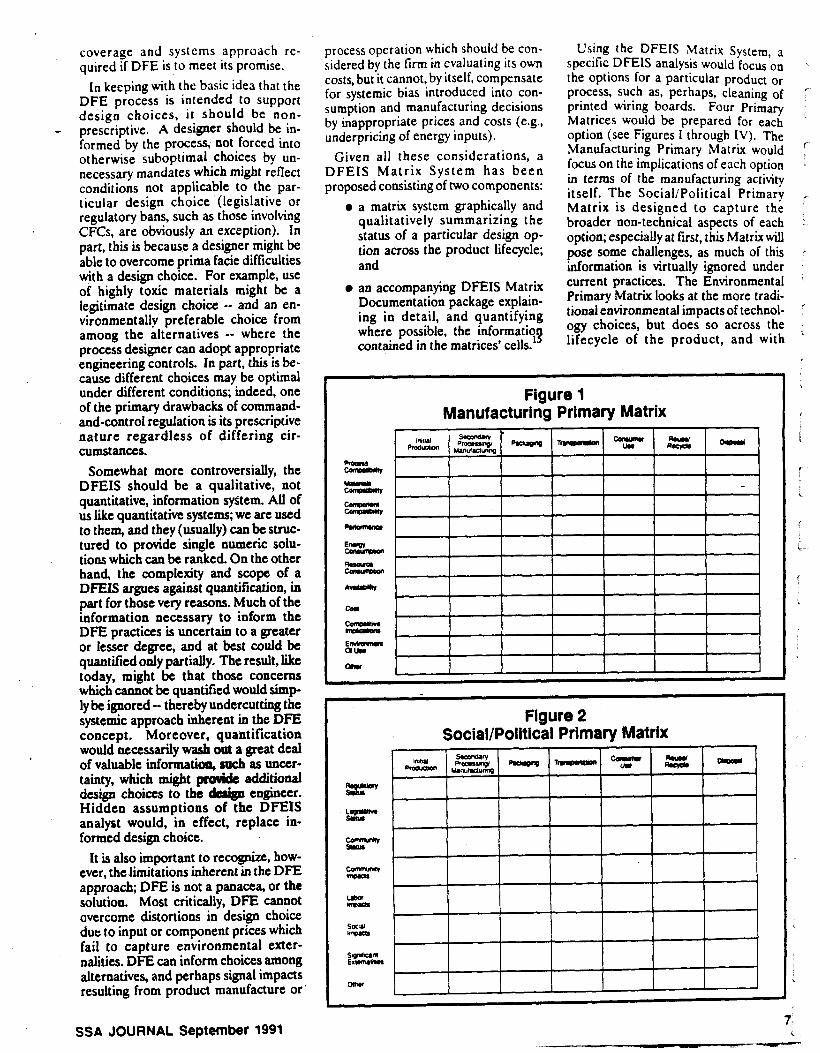
coverage and systems approach re- quired if DFE is to meet its promise.
In keeping with the basic idea that the DFE process is intended to support design choices, it should be non- prescriptive. A designer should be in- formed by the process, not forced into otherwise suboptimal choices by un- necessary mandates which might reflect conditions not applicable to the par- ticular design choice (legislative or regulatory bans, such as those involving CFCs, are obviously an exception). In part, this is because a designer might be able to overcome prima facie difficulties with a design choice. For example, use of highly toxic materials might be a legitimate design choice -- and an en- vironmentally preferable choice from among the alternatives -- where the process designer can adopt appropriate engineering controls. In part, this is be- cause different choices may be optimal under different conditions; indeed, one of the primary drawbacks of command- and-control regulation is its prescriptive nature regardless of differing cir- cumstances.
Somewhat more controversially, the DFEIS should be a qualitative, not quantitative, information sfitem. All of us like quantitative systems; we are used to them, and they (usually) can be struc- tured to provide single numeric solu- tions which can be ranked. On the other hand, the complexity and scope of a DFEIS argues against quantification, b part for those very reasons. Much of the information necessary to inform the DFE practices is uncertain to a greater or lesser degree, and at best could be quantified only partially. The result, like today, might be that those concerns which cannot be quantifted would simp- ly be ignored -- thereby undercutting the systemic approach inherent in the DFE concept. Moreover, quantification would necessarily wash out a great deal of valuable informatian, such as uncer- tainty, which might p d d e additional design choices to the dedp engineer. Hidden assumptions of the DFEIS analyst would, in effect, replace in- formed design choice.
It is also important to recognize, how- ever, the limitations inherent in the DFE approach; DFE is not a panacea, or the solution. Most critically, DFE cannot overcome distortions in design choice due io input or component prices which fail to capture environmental exter- nalities, DFE can inform choices among alternatives, and perhaps signal impacts resulting from product manufacture or
-
process operation which should be con- sidered by the firm in evaluating its own costs, but it cannot, by itself, compensate for systemic bias introduced into con- sumption and manufacturing decisions by inappropriate prices and costs (e.g., underpricing of energy inputs).
Given all these considerations, a DFEIS Matrix System has been proposed consisting'of two components:
0 a matrix system graphically and qualitatively summarizing the status of a particular design op- tion across the product lifecycle; and
0 an accompanying DFEIS Matrix Documentation package explain- ing in detail, and quantifying where possible, the informatio contained in the matrices' cells. 1'1
Using the DFEIS ,Matrix System, a specific DFEIS analysis would focus on the options for a particular product O r process, such as, perhaps, cleaning of printed wiring boards. Four Prim- Matrices would be prepared for each option (see Figures I through IV). The Manufacturing Primary Matrix would focus on the implications of each option in terms of the manufacturing activity itself. The SociaVPoliticaI Primary Matrix is designed to capture the broader non-technical aspects of each option; especiallyat first, this Matrix will pose some challenges, as much of this information is virtually ignored under current practices. The Environmental Primary Matrix looks at the more tradi- tional environmental impacts of technol- ogy choices, but does so across the lifecycle of the product, and with
Figure 1 Manufacturing Primary Matrix
I I I I I I I
~~
Figure 2 Social/Political Primary Matrix
%P z- w ca" npvu
L d a r WVam
sa u m.ar
2%%L OCNr
,
SSA JOURNAL September 1991 7 i

Figure 3 Environmental Primary Matrix
Figure 4 Toxicology/Exposure Primary Matrix
I I I I I I I - woun I
ulnudml C k m
oh rp*,
oh C-
e i I I 0" 1 I
Figure 5 Summary Matrix
Options
-1
categories which attempt to minimize the surgk ntedra fotation of current ap- proaches. Finally, the ToxicityExposure Primary Matrix looks at issues which are for the most part familiar, but again in a systemic, lifecycle way. The fifth matrix, the Summary Matrix (Figure V), gathers this information together in a single summary sheet.
Each Primary Matrix has two axes, one containing the life stages of the option, and the other consisting of issue categories bearing on the environmental suitability of the option under evalua- tion. For the most part the cells are self-explanatory; it is beyond the space allotted this paper to further explain each category.16
(Note that environment is being used quite broadly, to include impacts such as effects on resource and energy con- sumption patterns, the community, and society at large. If nothing else, the scope of the proposed DFEIS system demonstrates the extent to which cur- rent practices fail to consider many im- pacts attributable to design choices, and resultant manufacturing and processing activities.)
There are three possible entries for each matrix cell. A straight line through the cell means that that category is inap- plicable to the option under considera- tion. One or two pluses in a cell (" + " or " + + ") indicates positive environmental effects from the option, and the relative degree of benefit. The third type of entry is an oval, with the degree of en- vironmental concern keyed to the geometrical pattern in the oval. Blank would indicate the cell is applicable but the concem level is minimal; dots would indicate some concern; diagonal lines would indicate greater concern; and solid black would indicate the highest degree of concern.
Moreover, the degree of uncertainty associated with a particular rating would be indicated by the extent to which the pattern filled the oval. Thus, a com- pletely full oval would indicate absolute certainty regarding the rating, while a 25% filled-in oval would indicate con- siderable uncertainty regarding the rating. For example, benzene might ieceive a full, black oval in the Mam- malian Acute-Consumer Use cell of the Toxicity/Exposure Primary Matrix be- cause of its status as'a known human carcinogen. Methylene chloride, on the other hand, might receive a half-filled, black oval for the same cell, indicating a potentially serious issue (suspected car-
-
* SSA .JOURNAL Sebtember 1991
cinogenicity), but a significant degree of uncertainty associated Nith that rating.
The idea would be that an objective DFEIS analysis would be prepared, probably with input from regulators and the academic community as well as from industry, covering the range of options for a given product or process. This analysis would then be peer-reviewed and made widely available, for in- dividual firms to adopt to their specific design needs through their varient of the DFE process (adopted from the generic template). The end produd would be designs which, while not optimizing any single dimension, are environmentally preferable to those of today, which fre- quently reflect fragmented or even no environmental input.
Conclusion Increasing compliance concerns and
skyrocketing costs associated with waste management and disposal, combined with the recognition that environmental issues are now strategic for manufactur- ing fEms, suggest that traditional pat- terns of environmental management are obsolete. In particular, an cnd-of-pipe attitude towards environmental issues is not only obsolete, but a growing impedi- ment to national and global competitive- ness.
The only effective way to manage these issues is to drive environmental con-
- siderations and constraints into the design process. This will be a complex, time-consuming and difficult process, involving a need for extensive education of the design community and culture change throughout the firm. Implemen- tation of DFE practices, building on ex- isting DFX design principles, offers a mechanism by which this may perhaps be accomplished with the least dimculty and institutional resist-
About the Author Braden R Allenby, Senior Ebviron-
mental Attorney for AT&T, graduated c u i lade from Yale Unkrsity, and received his J.D. and MA. (EconomicS) from the University of Virginia in 1979. He received his M.S. in Environmental Sciences from Rutgers, where he is cur- rently a candidate for the Ph.D. in En- vironmental Sciences. He is currently Chairman of the American Electronics Association Design for Environment Task Force and the AEA Toic Substan- ces Control Act Task Force. Opinions
expressed in this article are the author's alone, and not necessarily those of AT&T or AEA.
References 42 U.S.C. Scc. 7401 as amended by PL 101.549, November 15, 1990. Sec.c.e. 42 U.S.C. Scc. 7413 (Clean Air Act).
ing: Managing the Transition to an Ecologically Sustainable Economy, In- temational Institute for Applied Systems Analysis and Camegie-Mellon Univer- sity, June 13,1991. pp. 536. The primary IegislativcvehiclesweK Sen. Reid's bill, S. 2637, lOlst Cong., 2d Sey., and Rep. Luken's bill, HR-5372. lOlst Cong., 2d SW. Scr. EPAs Advanced Notice of Proposed Rulemaking, 'CompKhenrive Review of Lead in the Environment Under TSCA", 56 22096 (May 13,1991). 42 U.S.C. Sec. 7412(d). For a general discussion of modem design procedures and the PRP process, see National Research Council.
(Washing- t0n.D.C.: National Academy Press), 1990, and National Research Council,
w. U. Ayes. 'Eco-RestruCtur-
. .
(Washington, D.C. National Academy Press), 1991, pp. 98-119. SCr D.A. Gatenby and G. Foo, 'Design for X: Key to Competitive, Profitable
63, No. 3, May/June 1990. pp. 2-13. There are accordingly few published materials on DFE. Some guidance may be obtrined from B.R Allenby, I h e Design for Emironmentil Infomation .!+stem', Interim Report for the Rutpn University Envi ronmenta I Science Depar tmen t , May 1991; and J. Sekutawrki, 'Design for Elwjronment',
Markets," Vol.
~JBSRUU June 1991. p 3. A more general discussion of related issues may be found in T.E. Graedel and L E Guth. The impact of Envlronmentai Issues on Matenalsand Processes*.- - Vol. 69. L o 6. \over t - ber/Dccember 1990, pp. 129.140
10 For an excellent iniroduction to the lifecycle concept. Soc~ety of Envlron- mental Toxicology and Chemistry (SmAC), "A Technical Framework for Life-Cycle Assessments", SETAC Foun- dation, January 1991.
11 %c&& D. McCmh, 'Recycling the Car", -, p. 106 et seq.
12 J. Azar. presentation to the American Electronics Association Design for En- vironment Task Force, Washington, D.C., May 10,1991.
13 As with D E , the concept of industrial ecology is so new that little published material is available. Interested t taden may wish to ~ N S C R.V. Ayres. 'In- dustrial Metabolism", in -an9 Envlronmcnl. ed. by J.H. Ausubel and H.E. Sladovick ((Washington, D.C.: Na- tional Academy Prcss), 1989. pp. 2349 and RA. Fmsch and N.E. Gallopoulos, "Strategicsfor Manufacturing", Scicntif!c
152. Vol. 261, NO. 3,1989, pp. 144-
14 Member organizations include Apple Computer, ATBT, Boeing. Digital, IBM, Hewlett Packard. Hughes Electronics, Motoda , Northern T e l w m , Pol_lroid, the U.SAir Force, and Xerox. Informa- tion concerning the AEA DFE Task Force may k obtained from Anne Ful- lerton d Digital, who heads the Com- munications Subcommittee, at 505493- 6045 (Fax 508493473), or the author, who chain the Task Force, at 908-204- 8440 (Fax 90R204-8S6S). The DFEIS concept, and the DFEIS Matrix System, arc propaed and ds- cussed in mom detail in Allenby. The Design for Environment Information SFtem', rvpn n.9. Interested d e n are-iefemd to the source in E 15, slpre for more informa-
15
16
tion.
SEISMIC PROTECTION FOR SEMICONDUCTOR INDUSTRY
* Full compliance with requirements of Toxic Cas Model Ordinance (CA, USA)
Intelligent seismic sensor technology provides accurate and reliable primary seismic measurement. Over 10,OOO installations worldwide.
Multiple activation levels permit a variety of additional client speciflc safety control functions.
9
ENVIRONMENTAL ISSUES
POLLUTION PREVENTION CONSIDERATIONS by Mabbett, Cappaccio & Associates Inc.
W itb the rtceotly enacted
tim Act (PPA) and state pollution pmcation and
toxig use reduction lam, implemen- tation of pollution Feation and waste m i n i t i o n technology has become more important in the oper- ation of PCB manufacatring, eloctr~ plating, and surface f i g facili- ties. In addition to the teguttory impehrs for pollution prcaurtioa, the
uxts and liabilities &tcd with *aste generatioa. This artide will address pollution prevention techniques that can reduce the oat of cad-of- pip wastewater t rcamt and com- ’pliance with hazardous waste man- agement requirements.
F ~ d d Polluti~n RCVCO-
PCB indusVy U driveqib bcrra~ing
REGULATORY BACK6ROUNO In 1 9 84 the Resource Coarcrva t ion
and Rccovery Act (RCRA), under which the havlrdous waste manage- ment regulations were promulgated, was reauthorized. One primaryobjec- tivc of this measure was waste mini- mization. Under the Resource Con- servation and Rccovay Act, waste minimization refers to the reduction or elimination ofwastegeneration via source reduction (that is, reducing waste at the point of generation), rccycling/reuse, and some forms of alternative treatment provided the volume or toxicity of the waste stream u reduced as opposed to the waste
being transferred from one environ-
58 PC FAB, JUNE 1992
mental medium to ~ 0 t h ~ (from watei to air, for exunple).
The f m of the RCRA m e n d - menu is hazardow waste raiuction. Howevtr, PPA of 1990 incorporates a multimedia appnr;lch to waste mini- mization, which includes reduction of wastes to ait, water, and land. PPA focuses on ~OUCOC reduction tu op posed tocad+f-pipcpollution Oontrol. Some state hrn have broidcned the scope eve0 fipnha vi8 toxia r e d u w wfiichfrmcrron”i2- ing or elhihating the ase of hazard- ous and toxic chanids ratha than the waste gcnaatai from the use of these chemicals (souroe reduction vs. =Ycw3/-).
APPROACH TO POLLUTIOIl PREVENTION
When startixig a pollution prcven- tioo program, it is important to review current process operations, identify constituents of concern, and deter- mioe the SOULCCJ and quantities of thcsc constituents. The process inven- tory should be conducted by somane familiar with PCB manufacturing operations and polIution prevention technology. A team approach is often the best choice. During the proms inventory phase,
information on factors such as rinsing operations, drag-out/drag-in of pro- cess chemicals, bath dump quantities and frcquencics, spills, industrial wastewater pretreatment system op- eration, and process water quality
ude
rcquuaocots is Usual Iyga thdTl l waste streams are iderrtifial m prioritid for further duat ion
Following the invcatary phasq a data b evaluated to identify
0 areas of potcothi ow- &a
which heips d4rm
0 of potential chemical ret
0 amas of potential rinse wa&u
This mluatioo ”ilLc &f- pipe treatment and dispobal rapins meats.odoptimiza&opportu-
rad asmomic feasibility is d r n t e d l before implemcntatioa techlrdcqk and tachniqus art selaacd.
tion within thc poccp .rtlfl
rtrram pollutant lads
LQUZCC raxnery and rcp3t
ooasavatioa.
itia. n e opportanitia’ t d laka l l
The f i t step in implanenting .nwr plan is to quantify all soorod of wastewater within the facility. Prt~ duction yield and quality control data should also be compiled to sene IS a benchmark for future camparisom as reduction tcchniquer are implement- a!. The quantity of wastewater from each source and the characteristics of that wastewater should be dctamind before a source reduction progran ti instituted. The major sources ef uxste
chemicals and wastewater producildo should bc critically evaluated fo: x- claim or reduction potential. Also. thc quality of the rinsewater require tdr

tach proccssstepshould bequantifid for rccycle and reuse purposes.
~ rag -ou t reduction techniqub can bc used to minimize the quantity of discharged chemiab. Though these technique have been mll document- Od in industry literature, they hrve not been widely implemented, par- ticularly in older faatitia.
These techniques rignfiantly re- duce wastewater tratment operating Q#U and a n bt uyd to document mcasurcs uka to rcducc hazardous waste generation. Dragout a n usu- ally be raiucad by 5096 or more depending on when a r d a l piece is withdrawn from the kth. Implemen- tation is therefore imperative.
The simplest form of drag-out re- duction, u i d e from rsducing a r - m e r into the ruooiog b is incor- poration of a still rinrs or drag-out. tmk. If the process brtb preceding. this dragout tank is h a t a i , the rolution can be used u makeup for that bath if proper parifkatioa men-. surer arc wed. II the pr#ru bath is unheated, awthu mans of handling the dragout d u t i m will be rquired.
Implementation of d n g o u t batch treatment a n show a taiuction in overall sludge genmtioo ampard to a continuous-flow treatment sys- tem. This method is impraaiul with significant quantities of dreg-out due to the Isbor-intensive nature of batch treatment. Cost-bend3 studies and the feasibility of instituting automat- ed reclaim masura would indicate this fact.
Numerous resource recovery tech- niques a n be used following a tab - lirhment of dragout tanks in the facility. The bat method depends on the waste chrractcristia. quantity, and il cost-benefit analysis based on the current market. Technical soci- eties. educational societies. and trade publications will help f;rmiliartte your staff with recovery techniques.
A cost-benefit rnrlysis should bc performed with 4 laboratory pilot
60 Pc FA& JUNE 1 9 9 2
test, if necessary, before a recovery technique is selected. Ion exchange, evaporative recovery, carbon a b o t g tion. membrane systems, and elecuo- lytic metal recovery hrvc been suc- ccufully applied to various metal- bearing waste streams. ,
Eistrolytic rocovay once a u l d k only u d OD baths with a high metal- lic ion amcawation. With the advent of methods for overcoming the cath- ode polarization probltms p o d by the dilute solution, recuvcry is b m - ing ,more widely usd for o " o n
~~
your f i i l i t y should have clearly defined hazardous
waste management policies, with
responsibilities def heated to control
generation in each process department.
metals. Some electrolytic recovery unit mtnufactumr arc using increased cathode area, agitation, or tempera- ture to minimize polarization prob- lems. Sia clcctrdytic recovery uses technology familiar to electroplaten, it has a basic appeal to that industry.
Another technology familiar to most ptocw personnel is ion exchange. Many facilities currently use ion ex- change systems on a portion of in- fluent city water todeionize the water for critical rinsing and process both makeup. Others have incorporated this tahnology to remove cations. anions, and reclaimed metal from contaminated rinse waters.
Studies performed by our company indicate that. for certain facilities. clatrolytic recovery and ion exchange kchnologies have significantly re- iuccd the cost of compliance com- iared to conventional precipitation
tahniques. Operation and m; nance (OQM) cxpmtes that \\
cansidered in determining the am compliance included chemicals; i rk power; labor and hazardous L,,, disposal: paru, supplia and labon maintenance and water drarga: mits; OkM service contracts; envkonmental impairment iiabii insurance premiums.
The effectiveness of any rccc technology depends on the soluttcc with which it is combinad and th chemial characteristia, the qua1 of d r a g a t , production hours. i.., emuent limits, the crrrcicncy of 11
unit, and the quantity of metal dudp reduction. Basic rinse w flow reduction Cochniqua should used on all waste stram that ha**- potential for raycle or rcckim metallic contaminants. Tbc louer tu
water flow, the more am effetir reclaim technologies such as napc tivc recovery, elcctraiialysu. E
electrolytic recovery will be. When investigating source rcd
tion options, don't ovulodt maoa m a t techniques. Your facility shoull have cfarly defined hazardous waw management policies, with rcspom bilitics delineated to control p n c t m
tion in each procus department. Certain companies have allotxt
hazardous waste disposal costs to t department responsible for the wasw generation, providing further ecn-. iomic incentive for the supervisor mplemcnt controls. By requiring thc; lupervisor of each proccrs depari- nent !hat generates such materials I ompletei hazardous waste manires he responsibility and authority IC. pired to reduce the quantity of wasi ,enerutd will r u t with the approprt te person.
M a n a p " should also cnsu::. hat the purchasing dcpartmcni ha. ledr understanding of procer, cheni als' impact on waste ireatnirrii ios1. his dcpJrtment should also cnru .
IC itnplciiient;rilon of proc'urciw
3
procedures that rquirc p u r in-house environmental manager’s approval pri- or to the introduction of new chemicals.
Source reduction does have certain disadvantages. Process area floor space is a vaIuable commodity, and in-plant source reduction techniques will con- sume some of that space. Mezzanines or remote ramcry systems caa be cstablishai to circumvent this prob- lem. Drag-out tanks require addition- al operator procedura, which pic- sene the possibility that the emplop may skip those work steps to keep up with production demands. Automat- ad liaa CPII be modified by the addition of multiple r h c and drag- out taaks, although such adjustments can k: oostly.
The addition of quipmeot such as pump, etccvolytic dk. elcctrodialy- sir oells, and ion uchsnge columns
also increases maintenance casts as- sociated with the proassing depart- ment. Further reclaim of dragout, particularly when it is uscd as a d e - up water for the pmwzing bath, quires increased attention to qual- ity control and aintaminant level control in the procear bath. Due to the impact of the RCRA
firms are also recycling much of their treated wastewater. Factors that h- pact the recyciiagdacision inciudt the dischrge iocntioa of tbc facilityr drag- out quantitr, pmcar and treatment chemical costs; bazudous waste con-
pairment liability insurance; and pro- cess quality uratrol impacts. A step
recycling is recommended to v d y quality control and product yields against the previously performed
cerr~, indudkg envirolMatll h-
by-step proccd~e for i m p l ~ ~ t i n g
benchmark influent water qw testing before more water is recyi
SUMMARY There arc economic and legal
sons for implementing pollution vention techniques in manufactun electroplating, and surface linisH facilities. Such measurer should U high priority next year.
3; 1.
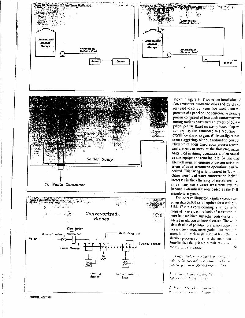
I '
Elchant Ruturn
1
I t
TO Waste Container
.- I' f 3 ' Con veyorized Rinses
Flow Muter M d
Wale?
[ Panel Sensor
Panel Sensor
f loir inp Conr err I ririea R/nsrs Bill I1
show in Figure 4. Prior to the installatior. )i' flow resuicton, automauc valves and panel >:rn. son uxd to control rsater flow based upon .-'.e presence of a panel on h e conyor. A c l e a r q process comprised of four such countcrcumnr rinsing stations conslimed an escess of 30.41111 gallons per day Based on weno. hours of o p x - tion per da). this amounted to a reductio:. :n overall flow rite of 25 gpm. While his figure T'\
seem staggering. without automatic conr,,l valves which open based upon process acd,:T. and a mealis to measure h e flow rate. m.;:n hater wed ill rinsing opentions is often m--d as the equipment remains idle. By crack::? chemical usage, an estimate of the cost sa\inr >I terms of waste treatment operations can 5, derived. This saving is summarized in Table +. Other benefits of water conserwion incl.; :e increases in the efficiency of metals renit:zl since iiianv waste u t e r treatnicnt sysrczi become liydraulicall~ owrloadcd as the F.:B manufacturer gro\\'s.
Fot the cases illusmted, capital espendiri-7% of less tliaii 58,000 \ w e required for R utili;. *: S164.44i \\ith R correspoading rctitrti 011 i l l ; - 3 . .
ment of' iwelve da\i. .I basis of iiieawril;. :-.; miat be rsi;iblished atid orher cocts C;III bt . ':. sidered in xldirioti to rhose dixusxd. The Ir ' .,
identific;itiolt of pollution I""wioa oppur.: : .- ties is ol)wv;t~ioli. iii\e>tigation .iittl ~t ic;~. iiieiii. It i h tinly t I i roi~.~I~ stiidy ot h l l l t ! I I C . . duction Imwiwcs a< \\ell ;IS dic t m i1.l.l
hetielii. i h t ilic 11ri11id ritriiit I:I.IIII;:~.~ : c;iii tr.ili/t. .I i'iijt saiit:., C