Electronic Systems - A1 27/04/2009 - areeweb.polito.it · Electronic Systems - A1 27/04/2009 2008...
19
Electronic Systems - A1 27/04/2009 2008 DDC - 2006 Storey 1 27/04/2009 - 1 ElnSysA1 - 2008 DDC ELECTRONIC SYSTEMS A – INTRODUCTION A.1 – Organization and contents » Goals and organization » Systems and modules » Analog and digital signals » Benefits of digital electronics Politecnico di Torino - ICT school 27/04/2009 - 2 ElnSysA1 - 2008 DDC INDUSTRIAL ENGINEERING DIGITAL ELECTRONICS MATH, INFORMATICS, PHYSICS, CIRCUITS, .. Basic concepts, functions, signals, …. Courses in Electronics (ideal) ELECTRONIC SYSTEMS ELECTRONIC DEVICES ANALOG ELECTRONICS 27/04/2009 - 3 ElnSysA1 - 2008 DDC INDUSTRIAL ENGINEERING DIGITAL ELECTRONICS MATH, INFORMATICS, PHYSICS, CIRCUITS, .. Courses in Electronics (actual) ELECTRONIC SYSTEMS ELECTRONIC DEVICES ANALOG ELECTRONICS DIGITAL ELECTRONICS ELECTRONIC DEVICES NOW 27/04/2009 - 4 ElnSysA1 - 2008 DDC Goals of the “Electronics” courses • Electronic systems – Basic concepts and techniques. » Systems as a set of functional units, defined by external parameters (models), » Use of feedback » Analog and digital signals and circuits: benefits and drawbacks » Interfaces and power handling » Examples of applications • Unique course in electronics for industrial engineers – What can be done with electronics • First of a sequence for ICT engineers – Applications and design in the following
Transcript of Electronic Systems - A1 27/04/2009 - areeweb.polito.it · Electronic Systems - A1 27/04/2009 2008...

Electronic Systems - A1 27/04/2009
2008 DDC - 2006 Storey 1
27/04/2009 - 1 ElnSysA1 - 2008 DDC
ELECTRONIC SYSTEMS
A – INTRODUCTIONA.1 – Organization and contents
» Goals and organization» Systems and modules» Analog and digital signals» Benefits of digital electronics
Politecnico di Torino - ICT school
27/04/2009 - 2 ElnSysA1 - 2008 DDC
INDUSTRIALENGINEERING
DIGITAL ELECTRONICS
MATH, INFORMATICS, PHYSICS, CIRCUITS, .. Basic concepts,
functions, signals, ….
Courses in Electronics (ideal)
ELECTRONIC SYSTEMS
ELECTRONIC DEVICES
ANALOG ELECTRONICS
27/04/2009 - 3 ElnSysA1 - 2008 DDC
INDUSTRIALENGINEERING
DIGITAL ELECTRONICS
MATH, INFORMATICS, PHYSICS, CIRCUITS, ..
Courses in Electronics (actual)
ELECTRONICSYSTEMS
ELECTRONIC DEVICES
ANALOG ELECTRONICS
DIGITAL ELECTRONICS
ELECTRONIC DEVICES
NOW
27/04/2009 - 4 ElnSysA1 - 2008 DDC
Goals of the “Electronics” courses
• Electronic systems– Basic concepts and techniques.
» Systems as a set of functional units, defined by external parameters (models),
» Use of feedback» Analog and digital signals and circuits: benefits and drawbacks» Interfaces and power handling» Examples of applications
• Unique course in electronics for industrial engineers– What can be done with electronics
• First of a sequence for ICT engineers– Applications and design in the following

Electronic Systems - A1 27/04/2009
2008 DDC - 2006 Storey 2
27/04/2009 - 5 ElnSysA1 - 2008 DDC
Course content
• Electronic systems• Sensors and actuators• Bode plots• Amplification• Control and feedback• Operational amplifiers• Semiconductors and diodes• Field-effect and bipolar transistors• Power electronics
27/04/2009 - 6 ElnSysA1 - 2008 DDC
What you should already know
• Circuit theory– RLC networks with controlled sources, Laplace transform (s)
• Mathematics– Linear equation systems, Differential equations (order I)
• Informatics – Boolean algebra, logic operators
• Physics – Basic mechanics, electric and magnetic fields
• Signal theory– Frequency domain analysis (qualitative)
27/04/2009 - 7 ElnSysA1 - 2008 DDC
Content of this lesson (A1)
• Course goals• Course organization• Exams • Prerequisites• Why “Electronic systems”• An example of system• Function and structure• Signals in the time and frequency domains• Analog and digital signals• Benefits of digital electronic systems
27/04/2009 - 8 ElnSysA1 - 2008 DDC
Course goals
• Develop skills, competencies, and abilities to:
– Translate the application requirements into specifications» how the specific application can be built as an electronic
system
– Design at the system level» functional characteristics, external behavior of modules» interface among modules
– Design at the circuit level» internal structure of modules» design flow of modules» error analysis
– Experimental verification of circuits behavior

Electronic Systems - A1 27/04/2009
2008 DDC - 2006 Storey 3
27/04/2009 - 9 ElnSysA1 - 2008 DDC
Grouping of course contents
• A Introduction
• B Transducers and amplifiers, circuit theory review
• C Operational amplifiers and feedback
• D Electronic devices
• E Logic circuits
• F Processing systems
27/04/2009 - 10 ElnSysA1 - 2008 DDC
Module organization (tentative)
• Room lessons and exercises– every week:
» 2+2+2+2 h lesson/exercise, or» 2+2+2 h lesson/exercise +3 h laboratory (to be confirmed)
• Total load (planned)– 15 lessons x 2h 30 + 60 (homework)– 5 exercises x 2h 10 + 10– 5 labs x 3h 15 + 8– total hours 55 78
– 55 room_hours + 78 self-study_hours = 133/27 ≈ 5 credits
27/04/2009 - 11 ElnSysA1 - 2008 DDC
Learning resources – book
• Reference textbook:– Neil Storey– Electronics: A Systems Approach– Prentice Hall, 2006, ISBN-13:9780131293960
• student resources– http://wps.pearsoned.co.uk/ema_uk_he_storey_electronic_3/
42/10999/2815814.cw/index.html
– Solved exercises– Self-evaluation tests
27/04/2009 - 12 ElnSysA1 - 2008 DDC
Learning resources - website
• Course website:– http://tjsic.tongji.edu.cn/corso/ElnSys– Copies of slides (for most lessons)– Solved exercises, Examples of written tests, …
• FTP site: – All slides + exchange of reports, homework, ..
• Other suitable textbooks– R.C. Jaeger, T.N. Blalock: Microelectronics
McGraw Hill, 2004
– J. Millman, A. Grabel: Microelectronics (II ed.), McGraw Hill/Boringhieri

Electronic Systems - A1 27/04/2009
2008 DDC - 2006 Storey 4
27/04/2009 - 13 ElnSysA1 - 2008 DDC
Learning resources in italian
• Course website (same course held in Torino):– http://ulisse.polito.it/matdid/
3ing_eln_L1740_TO_0/ETLCEnTO/index.htm
• Texbook (in italian):– Zappa: Fondamenti di Elettronica (II ed.), Esculapio, 2002
– Zamboni, Graziano: Introduzione all'analisi dei SistemiElettronici, CLUT, 2006 (collection of exercises)
• Distance learning course:– http://corsiadistanza.polito.it/on-line/Sistemi_ele/index2.htm
Storey, Electronics: A Systems Approach, 3rd Edition © Pearson Education Limited 20061.14
� This layout identifies slides from
Neil Storey: Electronics: A Systems Approach(reference textbook 1)
Slides developed for this course
Slide from Storey “ELN Systems” 1.3
Reference fromtextbook 1, withchapter.section
27/04/2009 - 15 ElnSysA1 - 2008 DDC
Examples and tests
• Examples (during the lesson)– Simple problems, fully solved
• End-of-lesson tests (slide at the end of each lesson)– Test to verify understanding of basis issues, or– Summary of lesson contents
• Room tests (sessions of exercises)– Statement of a problem– Sequence of questions– Require aggregation of contents from several lessons
• Samples of solved written tests (course website)
27/04/2009 - 16 ElnSysA1 - 2008 DDC
Test goals
• Faults must be identified as soon as possible– Before delivery to final customer– “missed learning” must be corrected before exam
• Goal of tests (self evaluation)– Find quickly “missed learning”
• Goals of exercises – Apply theory to new cases
• An Engineer will carry out design, not exams, but …– To become engineers you have (also) to pass exams– To pass exams you must be able (also) to solve exercises
Electronic Systems - A1 27/04/2009
2008 DDC - 2006 Storey 5
27/04/2009 - 17 ElnSysA1 - 2008 DDC
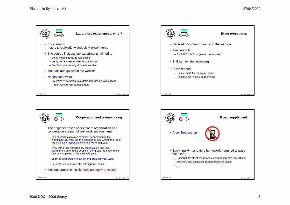
Laboratory experiences: why ?
• Engineering: maths & realworld � models + experiments
• The course includes lab experiments, aimed to– Verify models towards real cases– Verify correctness of design procedures– Practice teamworking & communication
• Manuals and guides in the website
• Needs homework– Preliminary workplan, role definition, design, simulations– Report writing (will be evaluated)
27/04/2009 - 18 ElnSysA1 - 2008 DDC
Exam procedures
• Detailed document “Exams” in the website
• Final mark F– F = 0,8 S + 0,2 L + [lesson notes prize]
• S: Exam (written exercise)
• L: lab reports– Unique mark for the whole group– Penalties for missed experiments
27/04/2009 - 19 ElnSysA1 - 2008 DDC
Cooperation and team-working
• The engineer never works alone: organization and cooperation are part of real work environments
– Lab exercises aim also to exploit cooperation in the workplace: carrying out the experience and writing the report are collective responsibility of the working group.
– Only with proper preliminary organization and task assignment among the people in the group the experiment can be completed in the available time.
– Learn to cooperate effectively and organize your work
– Better to set-up mixed skill & language teams
• the cooperation principle does not apply to exams
27/04/2009 - 20 ElnSysA1 - 2008 DDC
Exam supplement
• A cell-free course
• Each ring � mandatory homework (required to pass the exam)
– Radiation levels of cell phones, comparison with regulations– Structure and operation of silent bells (vibracall)– …

Electronic Systems - A1 27/04/2009
2008 DDC - 2006 Storey 6
27/04/2009 - 21 ElnSysA1 - 2008 DDC
Content of this lesson (A1)
• Course goals• Course organization• Exams • Prerequisites• Why “Electronic systems”• An example of system• Function and structure• Signals in the time and frequency domains• Analog and digital signals• Benefits of digital electronic systems
Storey, Electronics: A Systems Approach, 3rd Edition © Pearson Education Limited 20061.22
Electronic systems
� A system can be defined asAny closed volume for which all theinputs and output are known.
� Examples include:– an automotive system– an air conditioner.
� Inputs and outputs will reflect the nature of the system.
1.2
27/04/2009 - 23 ElnSysA1 - 2008 DDC
Systems and modules
• Any electronic system is composed by interconnected modules.
MODULE
MODULE
INTERCONNECTIONS
27/04/2009 - 24 ElnSysA1 - 2008 DDC
?
??
Why do we start from systems ?
• Most designers use modules and functional units designed and/or built by other people.
Electronic Systems - A1 27/04/2009
2008 DDC - 2006 Storey 7
27/04/2009 - 25 ElnSysA1 - 2008 DDC
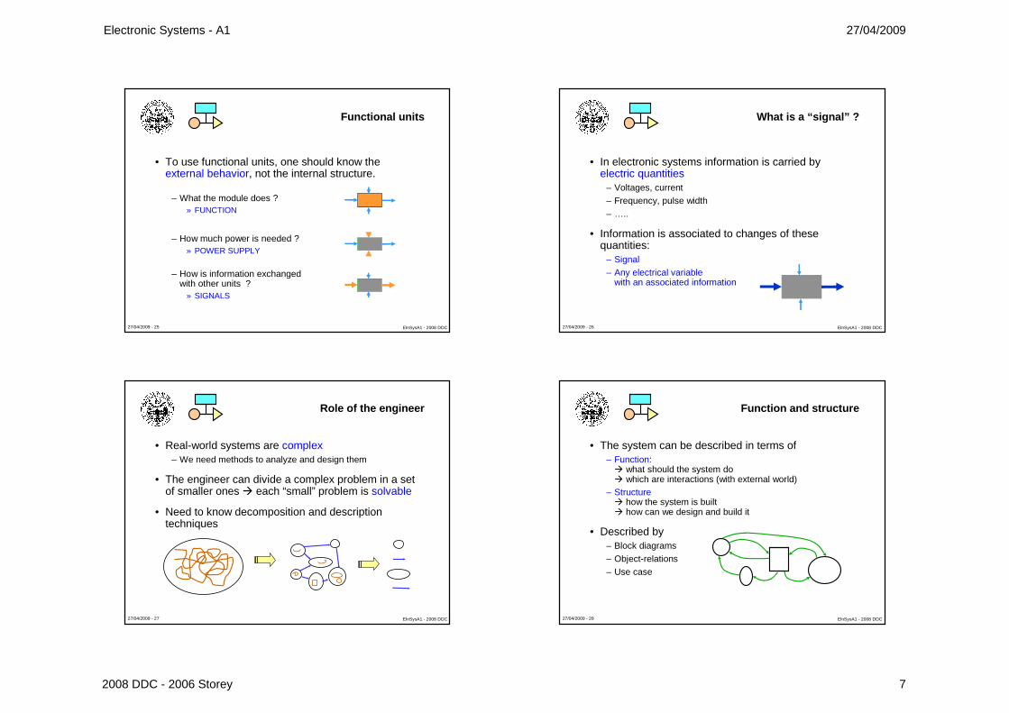
Functional units
• To use functional units, one should know the external behavior, not the internal structure.
– What the module does ?» FUNCTION
– How much power is needed ?» POWER SUPPLY
– How is information exchanged with other units ?
» SIGNALS
27/04/2009 - 26 ElnSysA1 - 2008 DDC
What is a “signal” ?
• In electronic systems information is carried byelectric quantities
– Voltages, current– Frequency, pulse width– …..
• Information is associated to changes of these quantities:
– Signal– Any electrical variable
with an associated information
27/04/2009 - 27 ElnSysA1 - 2008 DDC
Role of the engineer
• Real-world systems are complex– We need methods to analyze and design them
• The engineer can divide a complex problem in a set of smaller ones � each “small” problem is solvable
• Need to know decomposition and description techniques
27/04/2009 - 28 ElnSysA1 - 2008 DDC
Function and structure
• The system can be described in terms of – Function:� what should the system do� which are interactions (with external world)
– Structure� how the system is built� how can we design and build it
• Described by – Block diagrams– Object-relations– Use case
Electronic Systems - A1 27/04/2009
2008 DDC - 2006 Storey 8
27/04/2009 - 29 ElnSysA1 - 2008 DDC
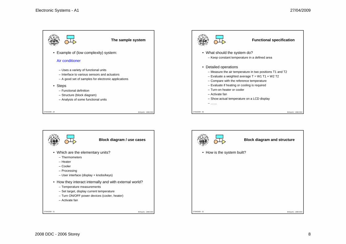
The sample system
• Example of (low complexity) system:
Air conditioner
– Uses a variety of functional units– Interface to various sensors and actuators– A good set of samples for electronic applications
• Steps – Functional definition– Structure (block diagram)– Analysis of some functional units
27/04/2009 - 30 ElnSysA1 - 2008 DDC
Functional specification
• What should the system do?– Keep constant temperature in a defined area
• Detailed operations– Measure the air temperature in two positions T1 and T2– Evaluate a weighted average T = W1 T1 + W2 T2– Compare with the reference temperature– Evaluate if heating or cooling is required– Turn-on heater or cooler– Activate fan– Show actual temperature on a LCD display– ……
27/04/2009 - 31 ElnSysA1 - 2008 DDC
Block diagram / use cases
• Which are the elementary units?– Thermometers– Heater– Cooler– Processing– User interface (display + knobs/keys)
• How they interact internally and with external world?– Temperature measurements– Set target, display current temperature– Turn ON/OFF power devices (cooler, heater)– Activate fan
27/04/2009 - 32 ElnSysA1 - 2008 DDC
Block diagram and structure
• How is the system built?
Electronic Systems - A1 27/04/2009
2008 DDC - 2006 Storey 9
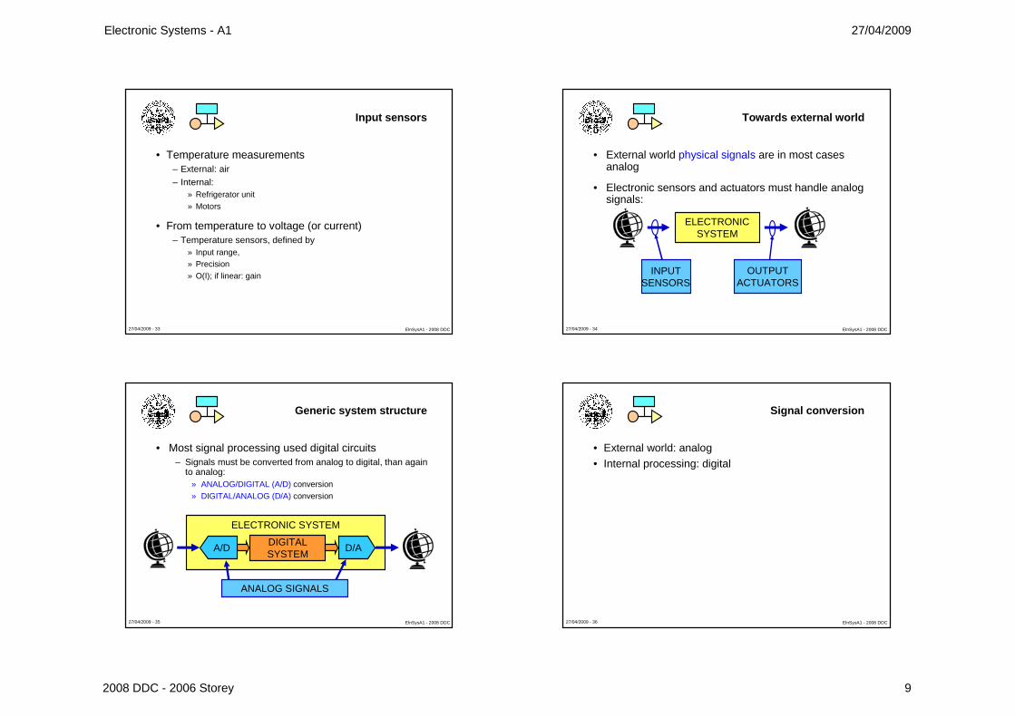
27/04/2009 - 33 ElnSysA1 - 2008 DDC
Input sensors
• Temperature measurements– External: air– Internal:
» Refrigerator unit» Motors
• From temperature to voltage (or current)– Temperature sensors, defined by
» Input range,» Precision» O(I); if linear: gain
27/04/2009 - 34 ElnSysA1 - 2008 DDC
Towards external world
• External world physical signals are in most cases analog
• Electronic sensors and actuators must handle analog signals:
ELECTRONICSYSTEM
INPUTSENSORS
OUTPUTACTUATORS
27/04/2009 - 35 ElnSysA1 - 2008 DDC
ELECTRONIC SYSTEM
Generic system structure
• Most signal processing used digital circuits– Signals must be converted from analog to digital, than again
to analog:» ANALOG/DIGITAL (A/D) conversion» DIGITAL/ANALOG (D/A) conversion
DIGITALSYSTEM
A/D D/A
ANALOG SIGNALS
27/04/2009 - 36 ElnSysA1 - 2008 DDC
Signal conversion
• External world: analog• Internal processing: digital

Electronic Systems - A1 27/04/2009
2008 DDC - 2006 Storey 10
27/04/2009 - 37 ElnSysA1 - 2008 DDC
Output actuators
• Refrigerator motor (ON/OFF)
• Fan (speed control)
• Air flow direction (position control)
• All these are Actuators
27/04/2009 - 38 ElnSysA1 - 2008 DDC
Motor control
• Function – What should a motor control do?
• Block diagram – How can we build a motor control system?
• Electric diagram – Which are elementary devices, and how are they
connected?
• Device datasheet – Which are the features of commercial devices used?
27/04/2009 - 39 ElnSysA1 - 2008 DDC
Why do we start from “systems” ?
• To use functional units, one should know the external behavior, not the internal structure.
– What the module does ?» FUNCTION
– How much power is needed ?» POWER SUPPLY
– How is information exchanged with other units ?
» SIGNALS
27/04/2009 - 40 ElnSysA1 - 2008 DDC
• Signals (carry information)• Power supply (carry energy)
• The power is distributed as DC voltage (Vsu)• Sometimes several voltages (+3,3, +5, -10, …)
Vsu
GND
INFOIN
INFOOUT
Where does power come from ?

Electronic Systems - A1 27/04/2009
2008 DDC - 2006 Storey 11
27/04/2009 - 41 ElnSysA1 - 2008 DDC
The power supply system
• Goal: distribute power with– Low heating– Low pollution (batteries !)– High efficiency
• Functional units – Mains power supply, batteries, …– Voltage regulators, battery chargers– Power handling units
• A complex subsystem
27/04/2009 - 42 ElnSysA1 - 2008 DDC
Content of this lesson (A1)
• Course goals• Course organization• Exams • Prerequisites• Why “Electronic systems”• An example of system• Function and structure• Signals in the time and frequency domains• Analog and digital signals• Benefits of digital electronic systems
27/04/2009 - 43 ElnSysA1 - 2008 DDC
Why do we start from “systems” ?
• To use functional units, one should know the external behavior, not the internal structure.
– What the module does ?» FUNCTION
– How much power is needed ?» POWER SUPPLY
– How is information exchanged with other units ?
» SIGNALS
27/04/2009 - 44 ElnSysA1 - 2008 DDC
Various types of signals
• Analog/digital• High/low/very low level
– Mike vs loudspeaker
• Frequency range– Audio vs RF
• Waveform – Sinewave, squarewave
• Information encoding– Cell phones– Digital TV
• …

Electronic Systems - A1 27/04/2009
2008 DDC - 2006 Storey 12
27/04/2009 - 45 ElnSysA1 - 2008 DDC
Signals in the air conditioner
• Input– Temperature– User setting
• Output– Refrigerator power– Fan power– Setting display
27/04/2009 - 46 ElnSysA1 - 2008 DDC
Low frequency signals
• In the circuits handling temperature and position the information changes very slowly: low frequency signals
• Example: sine signal (tone):– v(t) = V sin (ωt + φ)– V = peak value (volt, V)– ω = angular frequency (radians/second),
(frequency f = ω/2π, hertz, Hz)– φ = phase (radians, rad)
27/04/2009 - 47 ElnSysA1 - 2008 DDC
Analog signals
• audio
• Triangular wave
• temperature
time frequency
27/04/2009 - 48 ElnSysA1 - 2008 DDC
Radiofrequency signal
• The remote control circuit uses high frequency signals Radio Frequency (RF), around 800 MHz.
– Needs special amplifiers and wiring (coax cables).
• Example: RF carrier at 800 MHz
– Time domain
– Frequency domain
t
1,25 ns
f
800 MHz

Electronic Systems - A1 27/04/2009
2008 DDC - 2006 Storey 13
27/04/2009 - 49 ElnSysA1 - 2008 DDC
Time domain representation
A signal can be represented in the time domain ….
X axis: time
Y axis:amplitude
instrument: oscilloscope
t = 0
27/04/2009 - 50 ElnSysA1 - 2008 DDC
Frequency domain representation
…. or in the frequency domain:
asse X: frequenza
Y axis:amplitude
Instrument: spectrum analyzer
f = 0
fundamental
II harmonic
III harmonic
noise
27/04/2009 - 51 ElnSysA1 - 2008 DDC
Time-frequency relation
• Quick changes of the signal corresponds to high frequency components
time frequencyF = 0
bandwidth
27/04/2009 - 52 ElnSysA1 - 2008 DDC
Signal spectrum
• Periodic/not periodic» Spectrum with lines (∆F = 1/T) / continuous spectrum
• Limited in the time domain (from t = T1 to t = T2)» Unlimited bandwidth (from f = 0 to f = ∞)
• Limited bandwidth (from fA to fB)» Unlimited in the time domain (from t = -∞ to t = + ∞)
• Steep changes» high frequency components
• Actual signals» ~limited in time & frequency (few power out T1-T2 and F1-F2)
• Spectrum simulator for various waveforms: material � simulator and SW � signal spectrum

Electronic Systems - A1 27/04/2009
2008 DDC - 2006 Storey 14
27/04/2009 - 53 ElnSysA1 - 2008 DDC
Analog signals
• Analog signals are continuous– in the time domain: is defined for any time instant (within an
assigned interval 0, T)– in the amplitude domain: can assume any value (within an
assigned interval 0, S)
• Parameters:– Amplitude interval
» max and min values (dynamic range),
» DC component (if any)
– Spectral content» bandwidth, spectrum shape t
AS
0
0 T
27/04/2009 - 54 ElnSysA1 - 2008 DDC
Digital signals
• A digital signal is a sequence of numbers, in most cases binary (base 2)
– Discrete in the time domain: defined only at sometime instant (within a defined interval)
– Discrete in the amplitude domain: can assume only some values(within a defined interval)
8 bits, 28 = 256 values
t1
t2
t3
t4
t5
Storey, Electronics: A Systems Approach, 3rd Edition © Pearson Education Limited 20061.55
� Discrete signals are often described as digital signals.
� Many digital signals take only two values and are referred to as binary signals.
Representation of digital signals
27/04/2009 - 56 ElnSysA1 - 2008 DDC
Where do we find digital signals ?
• Most evident– Computers and information processing systems
• Most electronic systems contain digital parts– Audio and video equipment– Cellular and cordless phones
• Embedded electronic systems– Cars – Planes – White goods– …

Electronic Systems - A1 27/04/2009
2008 DDC - 2006 Storey 15
27/04/2009 - 57 ElnSysA1 - 2008 DDC
Errors with digital representation
• Values defined only at discrete times � Sampling– Sampling interval Ts, sampling rate Fs = 1/Ts– Can represent signals with bandwidth Fa < Fs/2
(Nyquist-Shannon theorem)» example: Fs = 20 kHz, Fa < 10 kHz
• Finite number of values � Quantization– N bit : 2N values, therefore
– Quantization error εQ = 100/2N % = 1M/2N PPM» example: 28 = 256 εQ = 0,4 %
• Simulator of quantization effects on Ulisse website at: learning material � simulators and SW � quantization
27/04/2009 - 58 ElnSysA1 - 2008 DDC
Binary signals representation
• Time evolution of a binary signal is represented by a bit sequence:
– Two state symbols 1/0, or H/L– Defined at Ts intervals (samples)
Ts
valueH
L
time
27/04/2009 - 59 ElnSysA1 - 2008 DDC
Ts
H
L
Timing diagrams
• States are represented by different voltage levels» High state � H, 1, ... → 3 V» Low state � L, 0, ... → 0,5 V
• The sequence of states becomes a timing diagram, similar to analog signals representation
value
timeH L H H L1 0 1 1 0
27/04/2009 - 60 ElnSysA1 - 2008 DDC
Noise and disturbance
All signals include a variable amount of random noise
the noise does not carry useful information
the noise does not carry useful information

Electronic Systems - A1 27/04/2009
2008 DDC - 2006 Storey 16
Storey, Electronics: A Systems Approach, 3rd Edition © Pearson Education Limited 20061.61
Distortion
� All systems distort electricalsignal to some extent– examples include clipping,
crossover distortion andharmonic distortion.
� Distortion is systematicand is repeatable.
1.3
Storey, Electronics: A Systems Approach, 3rd Edition © Pearson Education Limited 20061.62
� All systems also add noiseto the signals that pass through them.
� Unlike distortion, noise israndom and not repeatable.
� Noise cannot be removed from analog signals
� With proper techniques, noise can be removedfrom digital signals.
Noise
27/04/2009 - 63 ElnSysA1 - 2008 DDC
Analog signal degradation
• Any processing or amplification step adds noise.
• For an analog signal the noise represents a not recoverable information loss.
27/04/2009 - 64 ElnSysA1 - 2008 DDC
Digital signal degradation
• In a digital signal degradation caused by noise can be recovered, if limited within defined boundaries.

Electronic Systems - A1 27/04/2009
2008 DDC - 2006 Storey 17
27/04/2009 - 65 ElnSysA1 - 2008 DDC
Digital signal level restore
Thanks to amplitude discretization of digital signals, the levels can be restored to original values by comparison with a threshold
27/04/2009 - 66 ElnSysA1 - 2008 DDC
Digital signal recovery
• Digital signal can be recovered at regular intervals– Effects of noise do not cumulate
• Recovery allows to use long digital processing chains, to carry out complex operation
– Not possible with analog technique, due to noise cumulative effects
• To avoid information loss– Noise must be limited– Signal must be periodically rebuilt.
• Simulator of noise effects on Ulisse website: material � simulator and SW � segnale analogico/digitale con rumore
27/04/2009 - 67 ElnSysA1 - 2008 DDC
Towards external world
• Physical interfaces (transducers and actuators) handle in most cases analog signals
• The Electronic system uses analog signal to interact with the external world
ELECTRONICSYSTEM
ANALOG SIGNALS
27/04/2009 - 68 ElnSysA1 - 2008 DDC
A/D/A sequence
• Today electronics is mainly digital– signals must be translated from analog to digital, and then
from digital to analog:» ANALOG/DIGITAL (A/D) conversion» DIGITAL/ANALOG (D/A) conversion
ELECTRONIC SYSTEM
NUMERICSYSTEM
A/D D/A
ANALOG SIGNALS

Electronic Systems - A1 27/04/2009
2008 DDC - 2006 Storey 18
27/04/2009 - 69 ElnSysA1 - 2008 DDC
ELETTRONICSYSTEM
Analog ���� Digital ���� Analog
• Most part of electronic systems includes:– interfaces towards the analog external world (front-end)– A/D conversion– Numeric signal handling– D/A conversion – interfaces towards the analog external world (back-end)
ADC
Numeric system DAC
Actuators and analog
back-end
Sensors and analog
front-en
27/04/2009 - 70 ElnSysA1 - 2008 DDC
Changes in electronic systems
• Electronics systems are moving towards digital
A/D
Numericsystem
D/A Actuat
Sens
A/D
Numeric system
Actuators and analog
back-end
Sensors and analog
front-end
timeD/A
27/04/2009 - 71 ElnSysA1 - 2008 DDC
Electronics is going towards digital
• Only digital techniques allow complex processing– They do not cumulate noise– Digital integrated circuit have higher complexity then analog
ones
• Automatic tools for design and testing of digital ICs are available
– Digital ICs have lower cost
• The behavior of a digital circuit can be easily modified
– Software – Programmable logic circuits
27/04/2009 - 72 ElnSysA1 - 2008 DDC
Limits of digital
• Intrinsic errors caused by– Amplitude quantization
(errors related with bit number N),– Time sampling
(errors related with sampling rate).
• Digital variable are represented using analog signals (V, I, …)
– High speed digital signals requires analog techniques
• Some signals can be only analog (RF, …)– The boundary is continuously moving
(over ~1000 MHz almost everything is analog)

Electronic Systems - A1 27/04/2009
2008 DDC - 2006 Storey 19
27/04/2009 - 73 ElnSysA1 - 2008 DDC
Lesson A1 – final test
• Develop an example of functional (what does) and structural (how is built) descriptions for a system.
• The mains voltage (220V, 50 Hz) can be considered a signal?
• Which part of the spectrum use temperature signals?
• How many values can be represented with 8 bits?
• How are usually represented logic states?
• Describe the benefits of analog signals and systems
• Do all electronic systems have some analog part ?