Electronic Supplier Quality RequirementsElectronic Supplier Quality Requirements Uncontrolled when...
28
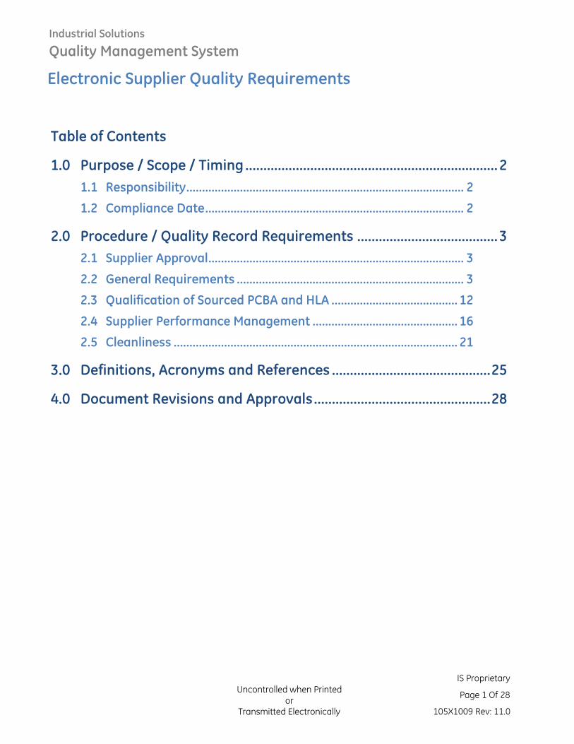
Industrial Solutions Quality Management System Electronic Supplier Quality Requirements Uncontrolled when Printed or Transmitted Electronically IS Proprietary Page 1 Of 28 105X1009 Rev: 11.0 Table of Contents 1.0 Purpose / Scope / Timing ...................................................................... 2 1.1 Responsibility........................................................................................ 2 1.2 Compliance Date .................................................................................. 2 2.0 Procedure / Quality Record Requirements ....................................... 3 2.1 Supplier Approval ................................................................................. 3 2.2 General Requirements ........................................................................ 3 2.3 Qualification of Sourced PCBA and HLA ........................................ 12 2.4 Supplier Performance Management .............................................. 16 2.5 Cleanliness .......................................................................................... 21 3.0 Definitions, Acronyms and References ............................................ 25 4.0 Document Revisions and Approvals ................................................. 28
Transcript of Electronic Supplier Quality RequirementsElectronic Supplier Quality Requirements Uncontrolled when...
Industrial Solutions
Quality Management System
Electronic Supplier Quality Requirements
Uncontrolled when Printed or
Transmitted Electronically
IS Proprietary
Page 1 Of 28
105X1009 Rev: 11.0
Table of Contents
1.0 Purpose / Scope / Timing ...................................................................... 2
1.1 Responsibility ........................................................................................ 2
1.2 Compliance Date .................................................................................. 2
2.0 Procedure / Quality Record Requirements ....................................... 3
2.1 Supplier Approval ................................................................................. 3
2.2 General Requirements ........................................................................ 3
2.3 Qualification of Sourced PCBA and HLA ........................................ 12
2.4 Supplier Performance Management .............................................. 16
2.5 Cleanliness .......................................................................................... 21
3.0 Definitions, Acronyms and References ............................................ 25
4.0 Document Revisions and Approvals ................................................. 28
Industrial Solutions
Quality Management System
Electronic Supplier Quality Requirements
Uncontrolled when Printed or
Transmitted Electronically
IS Proprietary
Page 2 Of 28
105X1009 Rev: 11.0
1.0 Purpose / Scope / Timing
This document outlines the quality requirements for the different stages of development of an electronics assembly produced for Industrial Solutions (IS) applications.
The scope of this document is to mandate the minimum requirements for all contract manufactuer’s (CM) manufacturing PCBAs for IS sites. Additional requirements can be defined by each IS site or business in the form of IS Engineering Technical Specifications or as notes on IS drawings. Product and process quality standards must at minimum meet per IPC 610 Class 2 and the requirements stated in this documentation, unless otherwise specified by site or drawing. The latest version applies, unless other specified.
1.1 Responsibility
As described in Procedure.
In general, copies of all required documents must be submitted by email or web application to the Supplier Quality Engineer (SQE) or Design Engineer by the Contract Manufacturer (CM).
All documents submitted to IS must be in English. Acceptable formats are Adobe PDF, Microsoft Excel or Microsoft Word.
1.2 Compliance Date
The following timeline is expected from all organizations within scope:
• Full compliance at the time of issuance of this document for all PCBAs quoted with IS-SRC-0002 (formerly EC-SRC-0002) after April, 1st, 2013. IS site or business in the form of IS Engineering Technical Specification or as notes on IS drawings can apply requirements to PCBAs in production prior to April 1st, 2013.
• Any system or specification conflicts to reference in this document, the following order of precedence must apply:
o Supplier Quality Requirement; IS-SRC-0002
o Purchase Order
o PCBA assembly drawing package and part specific specifications
o Latest Revision of this specification; 105X1009
o Documented reference in this specification
Industrial Solutions
Quality Management System
Electronic Supplier Quality Requirements
Uncontrolled when Printed or
Transmitted Electronically
IS Proprietary
Page 3 Of 28
105X1009 Rev: 11.0
2.0 Procedure / Quality Record Requirements
2.1 Supplier Approval
2.1.1 Minimum Quality System Requirements
CM must maintain a documented quality system as specified and required in IS-SRC-0002. Other acceptable quality management systems for PCBA include ISO 13485, ISO 14001, ISO 16949, and AS 9100.
2.1.2 Supplier Approval
In case of a NPI program requiring an approval of a new vendor, current CM new site, or on current projects requiring approval of an alternate CM, the following three surveys must be conducted by IS Sourcing and/or IS SQE to assess PCBA manufacturer capabilities:
Business Survey, Electronics Technical Audit (also known as Commodity Assessment or Technical Survey) and depending on manufacturing site location (i.e. Low Cost Country), a SRG (EHS) survey.
CM must achieve a score of 80% or greater on the IS Business survey and 80% or greater on the IS Electronics Technical Audit. In case of a score lower than 80% in any survey, CM must present an action item list with corrective actions, implementation date and owner and a second survey must be scheduled by IS SQE in less than 180 days to validate corrective actions have been implemented and closed and survey score will be re-assessed.
An SRG/EHS audit will be required if CM Manufacturing Location is based in a region which requires an audit. CM must have no red flags on SRG/EHS audit to be approved as an IS Supplier.
On NPI programs these surveys should be conducted by IS Supplier Quality personnel, and with IS Sourcing and / or IS Technology if requested, prior to awarding a contract.
IS SQE will define frequency of future audits and surveys on the Supplier Surveillance Plan for the specific IS manufacturing location or Commodity.
2.2 General Requirements
2.2.1 Traceability
• CM must have systems supporting lot traceability which includes SMT component lot traceability, as well as electrical testing, rework and packaging processes traceability. Each PCBA must be serialized at the start of the assembly process with a unique number label (i.e. labeled, inkjet marked or laser etched) to help trace the assembly through the entire manufacturing process. Specific requirements on identification of serial numbers must be provided by IS business or site. At minimal each serial number must include a code indicating the manufacturer name, manufacturer location, a date code
Industrial Solutions
Quality Management System
Electronic Supplier Quality Requirements
Uncontrolled when Printed or
Transmitted Electronically
IS Proprietary
Page 4 Of 28
105X1009 Rev: 11.0
indicating the serialization date, and unique serialization number for individual PCBA.
• Each serial number must have the following information associated with it:
i. Date and time of serialization
ii. Manufacturer part number and date code of each component, including PCB, on the PCBA
iii. Each MAC address allocated to the unit (when applicable)
iv. Date and time of each successful product quality conformance test
• Records of each serial number and the associated information must be kept for at least three years.
• In case a top level assembly (parent) is directly sold to IS and is conformed of two or more sub-assemblies (children), information must be available to allow geneology traceability to the sub-assemblies serial numbers.
• In case of a CM or sub-tier supplier quality issue, CM must be able to provide the following information in less than 24 hours:
i. Shipments and Invoices # affected (shipping tracking numbers).
ii. Specific Pallets affected within affected shipments. (if applicable)
iii. Specific Boxes where suspect material was shipped.
iv. Specific Range of Serial Numbers of PCBAs affected based on specific date codes or lot numbers of suspect components.
v. Test historical data (at minimum ICT and FCT) of Serial Numbers affected.
2.2.2 Electrostatic Discharge (ESD) Protection
• CM must establish an ESD control program in accordance with ANSI/ESD S20.20 or BS EN 61340-5-1:2016.
• An internal ESD audit schedule must be executed and corrective actions must be planned and closed in a timely manner in case of any finding. ESD audits may be performed by certified ANSI/ESD S20.20 or BS EN 61340-5-1:2016 external agency, if internal audits are not performed.
Industrial Solutions
Quality Management System
Electronic Supplier Quality Requirements
Uncontrolled when Printed or
Transmitted Electronically
IS Proprietary
Page 5 Of 28
105X1009 Rev: 11.0
• The use of gloves or finger cots is required to prevent contamination of parts and assemblies. Gloves and finger cots must be carefully chosen to maintain ESD protection. Handling with clean hands by board edges using full ESD protection is acceptable when approved by Industrial Solutions.
• ESD protection must be worn by all persons on IS dedicated lines at CM site.
2.2.3 Component Material Handling and Purchasing
• Per IS-SRC-0009, all components must be sourced directly from OEM or OEM Authorized Distributors. When the use of an Independent Distributor is necessary, the supplier must only use independent distributors that are listed on IS Approved Supplier List. Buying from Independent Distributor (Spot Buy) requires a Supplier Deviation request to be submitted to IS for approval in case components are urgently needed and there is no other feasible option to obtain parts from authorized channels.
• The stock room for material storage must have conditions of ambient temperature of 23 C +/-5C at 35% + 15%/- 15% relative humidity and must be properly controlled and monitor at least every 24 hours. Moisture Sensitive Components must be handled, stored, and processed per IPC/JEDEC J-STD-033. Incoming material must be stored and sealed in the manufacturer original package; resealed reels and open package material must follow the material floor life and moisture sensitivity level guidelines defined by IPC/JEDEC J-STD-033. If floor life is exceed, IPC/JEDEC J-STD-033, must be followed to reset shelf life and repackaging.
• Material shelf life is the minimum time that a dry-packed, moisture-sensitive device can be stored in an unopened moisture barrier bag (MBB) such that a specified interior bag ambient humidity is not exceeded by a Humdity Indicatior Card (HIC) in the package. Usage of a component beyond the specified shelf life could compromise product long term reliability. Material shelf life must follow active and passive component shelf life specification defined by IS as two (2) years, IS engineering specification, or component OEM’s published documentation, whichever is less.
• Solderability testing, per IPC/EIA/JEDEC J-STD-002,shall be performed on components with shelf life older than two (2) years old and less than five (5) years old upon the date of the component manufacture. Any use of parts older than 5 years requires the written approval of IS. Sample size shall be a minimum of 5 parts, selected randomly throughout the lot, from each unique date code. Once the solderability test has been conducted and passed,
Industrial Solutions
Quality Management System
Electronic Supplier Quality Requirements
Uncontrolled when Printed or
Transmitted Electronically
IS Proprietary
Page 6 Of 28
105X1009 Rev: 11.0
material must follow IPC/JEDEC J-STD-033 to reset shelf life and may be used for an additional two years before the components must be re-tested for solderability.
i. Leaded parts: J-STD-002, Test A, A1 method and acceptance criteria apply
ii. Leadless parts: J-STD-002, Test B, B1 method and acceptance criteria apply
iii. Ball grid arrays (BGA): The PWA supplier shall assemble a sample quantity of PWAs, using normal production methods. Acceptance criteria shall be per IPC-A-610, using X-Ray and visual inspection methods.
iv. Other solderability test methods are acceptable if approved by IS Supplier Quality.
v. In addition, Reliability tests (i.e. Temperature cycling, Autoclave, etc.) might be required depending on the application and IS specific requirements for the project in question.
• For Last-Time-Buy (LTB) material requiring long term storage, the LTB material must be stored in proper condition (i.e. vacuum sealed moisture barrier bag) to limit the impact of material reliability and solderability. All products purchased with the intent of storing beyond Shelf Life limits need to be tested for Solderability to extend solderability shelf life every two years. Test is performed at the end of each shelf life period to extend solderability life.
• A Supplier Deviation request to be submitted to IS and approval should be obtained in order to process:
i. LTB material exceeding its shelf life.
ii. Sub-tier supplier ECN/EOL notifications
iii. Spot Buys
iv. Use of components or bare PCBs exceeding material shelf life.
2.2.4 Component Compatibility
• The recommendations in the component manufacturer’s data sheets shall be taken into account when determining the compatibility of individual components with the reflow, wave, selective and hand solder processes and cleaning processes.
• Components deemed to be sensitive to any production process shall be fitted post that process unless when approved by IS.
Industrial Solutions
Quality Management System
Electronic Supplier Quality Requirements
Uncontrolled when Printed or
Transmitted Electronically
IS Proprietary
Page 7 Of 28
105X1009 Rev: 11.0
2.2.5 Thermal Processes
• Each CM’s production line and/or revised combination of solder and cleaning process must be qualified. Any change in type or modification of soldering or cleaning equipment (reflow oven, wave solder, wash, hand solder, rework, etc.) or change in materials used in these processes must require re-qualification. Because the thermal profile, amount of flux, and wash efficiency, (if washed) vary, material manufacturer’s test data is not acceptable.
• Profiles should be established for each IS PCBA to insure the flux is properly activated, components are not thermally stressed, and proper solder joint formation is achieved. A minimum of four (4) thermocouples or temperature labels must be applied to the top and bottom of the PCBA to insure these requirements are met. Infrared sensors could also be used.
• Where multiple reflow ovens or wave solder machines are used in a work cell, an individual profile must be qualified on each machine.
• Changes to the PCBA design, the reflow oven, wave solder machine or processes, must require the Supplier to review the profile to insure the requirements as stated are met.
• Profiles must be archived for at a minimum of three years and available for IS review upon request. The data record must define all applicable machine parameters and serial numbers, thermocouple locations, PCBA part number and revision, date, and the person performing the profile.
• All soldering materials (solder paste, wire, bars, and fluxes) must be approved by IS and compatiable with other materials used.
2.2.6 Washing Processes
• When IS does not explicitly specify use of wash process or when there are no process limitations due to solder paste/flux combination, it is preferred that PCBA are built using a process that does not require washing at the final assembly. However, if after a review of the process a wash step is required, it must meet the following requirements:
i. De-ionized water is mandatory, Tap water is not acceptable. De-ionized water resistivity level must be greater than ten mega ohms per centimeter (>10 Mohms/cm) after recharge or regeneration.
ii. The equipment must be capable of continuously monitoring the wash water as well as waste water and have the capability to automatically turn off or trip alarm if
Industrial Solutions
Quality Management System
Electronic Supplier Quality Requirements
Uncontrolled when Printed or
Transmitted Electronically
IS Proprietary
Page 8 Of 28
105X1009 Rev: 11.0
cleanliness limits of the wash water or final waste water fall below five mega ohms per centimeter (<5 Mohms/cm).
iii. Automated equipment employing Wash, DI Water Rinse, and Dry stages shall be used for PCBA cleaning.
iv. Cleaning of PCBAs shall be carried out following the final soldering operation (whether SMT Reflow, Wavesolder or Hand Solder) prior to any non-washable components being fitted. All components deemed to be sensitive to the cleaning process shall be fitted afterwards.
v. Only IS approved saponfier shall be used in the Wash process.
vi. Under normal operating conditions, all IS PCBAs requiring washing processes shall be washed within 24 hours of reflow soldering, to ensure optimal removal of flux residues and other surface contaminants. However, due to operational reasons or exceptional circumstances, PCBAs may be washed up to a maximum of 72 hours after reflow soldering. If assembly process requires multiple soldering operations where more than 72 hours elapses, the PCBA must be washed after each individual soldering process.
2.2.7 Conformal and Harsh Environment Coating Processes
When Conformal or Harsh Environment Coating is required by IS:
• When technically feasible, the preferred application method is automated spray or dispense machine, unless otherwise stated in IS drawing/specification.
• The preferred coating should be per drawing, specification, or bom or if not specified, Dow Corning 3-1953 should be used.
• Thickness of coating should be per drawing, specification, or IPC specification
• PCBAs must be clean of any flux residue and meet Ionic Chromatography limitation level in IS Specification Table 1 in Section 2.4 or as specified by IS Engineering per part drawing or per IS specific site board cleanliness specification before Coating process. If Ionic Chromatography limitation levels are higher than Table 1, then a cleaning step is recommended to meet cleanliness specification prior to conformal coating.
• Other coatings can be proposed at the beginning of the NPI program. To be considered, alternate conformal coating materials recommended must meet the following conditions:
Industrial Solutions
Quality Management System
Electronic Supplier Quality Requirements
Uncontrolled when Printed or
Transmitted Electronically
IS Proprietary
Page 9 Of 28
105X1009 Rev: 11.0
i. Be UL and/or IPC 630 approved.
ii. Have a cost advantage to preferred coating.
2.2.8 Rework and Repair Processes
• Rework process must be fully compatible to guidelines of IPC 7711/7721 Rework, Repair and Modification of Electronic Assemblies.
• Rework area must have clearly marked areas for storing any WIP which is classified as non-conforming material. Material flow must be controlled to prevent any mixing of good and suspected/rejected parts.
• Full traceability is mandatory in rework area. CM must be able to trace any serial number that has been reworked, identify failure mode and have rework actions stored in database with operator, time, and date when board was released from rework area.
• Rework equipment must follow calibration schedule.
• Operators in rework / repair areas must have specialized training on IPC 7711/7721 or compatible standard and must be evaluated before working in mass production. Annual internal recertification program must be conducted.
• If a PCBA needing rework has any moisture sensitive components, the PCBA must be baked to remove any potentially damaging moisture before rework may begin.
• Except for BGA, QFN and hidden solder joints, every reworked solder joint or touch-up operation must be inspected using magnification aid according to J-STD-001. Rework of BGA or QFN and similar packages with hidden solder joints must be inspected with X-ray equipment and Electrical test (i.e.: ICT or FCT) prior to release to next manufacturing step.
• A supervisor or second operator must re-inspect every reworked PCBA.
• Cleanliness requirements identified in Section 2.4 of this document must be met after rework or repair.
2.2.9 Lead Trimming
• Whenever possible, lead cutting/trimming should be performed prior to soldering. If lead cutting/trimming must be performed after soldering, the solder termination shall be visually inspected at 10X magnification to ensure that the original solder connection has not been damaged and touched up with solder.
Industrial Solutions
Quality Management System
Electronic Supplier Quality Requirements
Uncontrolled when Printed or
Transmitted Electronically
IS Proprietary
Page 10 Of 28
105X1009 Rev: 11.0
2.2.10 Automated Inspection
• CM must have Solder Paste Inspection controls to measure solder paste area and volume applied on PCB solder pads. Techniques available, but not limited to, are:
i. Automatic 2D or 3D inspection on solder printing machine.
ii. Off-line solder paste height measurement with specialized equipment.
iii. In-line Automatic Optical Inspection for solder paste printing (recommended for fine pitch components, QFN and BGAs pads).
• IS recommends use of Automatic Optical Inspection (AOI) equipment after reflow to inspect quality of solder joints, component polarity and placement as part of test coverage of PCBA unless mandatory by IS engineering specification.
• IS recommends use of Automatic Visual Inspection (AVI) equipment after wave to inspect quality of solder joints, component polarity and placement as part of test coverage of PCBA unless mandatory by IS engineering specification
• In case of BGAs, QFN or other package type where solder joint and/or hole fill is hidden below component body, X-ray inspection is required with a miminum auditing of 10% of PCBA per production lot unless additional frequency is identified by IS Engineering specification/drawing. An individual ball must not have overall void area of 25% and total component’s voids must be less than 10% of covered surface area.
• The need of above equipment is based on Coverage Report analysis using the PCOLA-SOQ method to achive 100% coverage.
Industrial Solutions
Quality Management System
Electronic Supplier Quality Requirements
Uncontrolled when Printed or
Transmitted Electronically
IS Proprietary
Page 11 Of 28
105X1009 Rev: 11.0
2.2.11 Packaging Requirements
• In addition to requirements by IS-SRC-0002, the following requirements applied:
i. A package sample must be delivered to the receiving site for approval prior to Pilot build.
ii. Packaging must adequately protect parts from physical and ESD damage and satisfactorily meet Ship Test requirements per Fed Ex test as defined in Cycle II, Schedule C (FedEx) or ISTA 1C testing procedure.
iii. Packages should have dividers inside to separate individual PCBAs
iv. Individual PCBAs must be stored in an ESD-safe package. ESD-safe packages (i.e. Dissipative Metallized Shielding Bags/Conductive Cardboard) must have a surface resistivity value of less than 1x10^11 ohms @100 volts or per IS Engineering Site Specification. When qualifying Anti-static Shielding bags type III, these must be tested according to MIL-B-81705C standard.
v. When Pallets (set of boxes) are requested, palletizer plastic must cover 100% of the area of the pallet to avoid water damage to packages and PCBAs.
vi. Individual package weight maximum is 35 pounds or as per IS site requirements.
vii. Packages are to be palletized (IS preferred method) and shipped on pallets made from materials approved by the materials manager of the IS receiving site.
viii. Each package must at a minimum be labeled as specified by IS-SRC-0002.
2.2.11 Printed Cirucit Boards (PCB/Bare Boards)
• Only IS approved PCB suppliers may be used for circuit board assemblies.
• Other PCB suppliers can be proposed at the beginning of the project. To be considered, alternate PCB suppliers must meet the following conditions:
i. Become an approved and qualified PCB supplier for IS.
ii. May have a cost advantage to other qualified vendors listed on AVL.
• The PCB must comply with IPC-A-600 Class 2
Industrial Solutions
Quality Management System
Electronic Supplier Quality Requirements
Uncontrolled when Printed or
Transmitted Electronically
IS Proprietary
Page 12 Of 28
105X1009 Rev: 11.0
• Cleanliness requirements identified in Section 2.3.9 of this document must be met after rework or repair.
2.3 Qualification of Sourced PCBA and HLA
2.3.1 First Piece Part Qualification
Prior to Purchase Order for First Piece Samples, IS SQE or IS Buyer will inform CM of First Piece Qualification Requirements, sample quantity and due dates. Prior to shipping Pre-Production parts, a First Piece Qualification Report must be electronically submitted via email to IS SQE for analysis and consideration of approval. At minimum, FPQ Reports require 5 samples and the following requirements to be completed:
• Measurement of all dimensions specified on the IS released drawings (i.e. Gerber files, bare PCB drawing, Assembly drawing, etc.).
• Verification that all components match the vendor and part number listed on the IS master or approved Bill of Material /Approved Vendor List (BOM/AVL).
• Verification that all drawing notes are in compliance
• Verification of the correct software revision with checksum if applicable.
• When requested by IS SQE, a Capability study with Gage Repeatability Reproducibility (GRR) study on Critical to Quality (CTQ) parameters as specified on the drawings.
• Process yield at all major manufacturing steps with Pareto of defects and applicable corrective actions.
• Complete and up to date manufacturing process plan (MPP)
• Complete and up to date product quality plan (PQP).
• Complete and up to date process Failure Mode Effects Analysis (PFMEA)
• Test Strategy and Coverage that been approved by IS technology and supplier quality engineer
• Ionic Chromatography test results that meet the IC limits.
• Packaging Plan that been approved by the IS receiving site.
• Inspection procedures must be in accordance with IPC-A-610, Class 2 or as specified by IS site.
Refer to Industrial Solutions Supplier Quality Requirements IS-SRC-0002 on Supplier Central for additional Qualification requirements.
Industrial Solutions
Quality Management System
Electronic Supplier Quality Requirements
Uncontrolled when Printed or
Transmitted Electronically
IS Proprietary
Page 13 Of 28
105X1009 Rev: 11.0
CM is responsible to provide access and to support Agency Approvals (UL, CE, etc.) certifications at a certified agency lab in case they are required by IS drawing.
When requested by IS or specified in drawing, CM must present convincing evidence (MSDS, Chemical Composition Tables or equivalent) that the CM’s Process non-AVL and MRO Materials is complying with EU ROHS and/or REACH regulations.
2.3.2 Process Consumables
• MSDS are required for all process materials including:
i. Solder material, flux, adhesives, conformal coating.
ii. Other chemicals used in the manufacturing process.
iii. Flame retardants - detailed chemical composition is required for all components using Flame retardants.
2.3.3 Manufacturing Process Plan (MPP)
In addition to requirements for MPP by IS-SRC-0002, MPP must contain the following information:
• Include detailed description of equipment including make and model.
• Describe equipment layout and factory arrangement. Include description of manufacturing and inspection steps. Include high level documentation number for each process step.
• CM is required to provide latest IPC form IPC-1720 for submission in the First Piece Qualification.
2.3.4 Product Quality Plan (PQP)
In addition to requirements for PQP by IS-SRC-0002, MPP must contain the following information, following processes must be controlled using Statistical Process Control :
• Solder Paste Height and Volume (Continuous variable)
• Deionized Water Washing (Continuous variable)
• PCBA Process Cleanliness (Discrete variable)
2.3.5 Characteristic Accountability and Verification (CAV)
• CM to provide evidence that PCBA meet IPC 610 Class 2 or specified Class level per IS Specification/Drawing, with report from IPC 610 certified inspector (CIS) from CM or third party, as agreed to between IS business and CM. Empirical data for solder hole fill and hidden solder joints that can’t be inspected by CIS, is required. This may include but not limited to X-RAY or SEMS images.
Industrial Solutions
Quality Management System
Electronic Supplier Quality Requirements
Uncontrolled when Printed or
Transmitted Electronically
IS Proprietary
Page 14 Of 28
105X1009 Rev: 11.0
• When requested by IS, a Gage R&R study using ANOVA method is required for critical operations (i.e. visual inspection, test, dimensional checks, etc.).
• When requested by IS, Capability studies are required to be performed for each Critical to Quality (CTQ) specifications.
• Critical Internal process (CTP) parameters can also be considered as CTQ on SPC system when requested by IS SQE.
• The minimum sample size for computing the capability (Cpk) must consist of 30 parts made up of 6 logical subgroups of 5 consecutively made parts each. Subgroups are selected in a way as to maximize the exposure to varying conditions.
2.3.6 Process Failure Mode and Effects Analysis (FMEA)
• CM must conduct and present a process FMEA. All high-risk FMEA items must be addressed in the Product Quality Plan. This process must be reviewed periodically for effectiveness and must include continuous improvement and lessons learned.
• All FMEA concerns must have descriptions of current controls and recommended actions. The FMEA must reflect the entire manufacturing process from receiving through shipping.
• The CM must ensure all failure modes observed during pre-production runs are captured on the PFMEA. The CM must ensure failure occurrence and the detection ability of these failures, observed during pre-production runs correlate with the occurrence and detection numbers documented on the FMEA.
2.3.7 Detailed Drawing, Manufacturing, and Producability Review
In addition to requirements by IS-SRC-0002, Review must contain the following information:
• The CM should present a complete Design for Manufacturing (DFM) report for PCBA and PCB Layout. Specific design guidelines required in order for designs to be built in the CM factory. Specify any limitations such as PCB trace line width, maximum PCB sizes, component sizes the equipment can handle.
• The CM should present a complete Design for Testability (DFT) report to meet 100% coverage of the PCBA using the PCOLA-SOQ method, include Test and evaluation capabilities (i.e. number of test chambers, capacity, and temperature/humidity capabilities, availability of electrical testers/fixtures like ICT and/or Flying Probe and/or FCT, etc.). Specify any limitations that would prevent 100% coverage value using
Industrial Solutions
Quality Management System
Electronic Supplier Quality Requirements
Uncontrolled when Printed or
Transmitted Electronically
IS Proprietary
Page 15 Of 28
105X1009 Rev: 11.0
the PCOLA-SOQ method to indicate the capability of the PCBA manufacturing test process to detect components and solder defects.
2.3.8 Test Strategy Approval
CM shall test 100% coverage of all PCBA as measure by the PCOLA-SOQ method with In-Circuit Testers (ICT) and Functional Circuit Testers (FCT) prior to shipment to IS sites. CM shall provide test strategy to plan AOI, X-ray, or visual inspection to detect defects not otherwise detected by the ICT and FCT test plan. As with any tool or equipment, the ICT and FCT fixtures must be fully documented and qualified.
• In-Circuit Testing and Functional Testing must be qualified per the requirements of SI500116 or as specific by IS Site Specific documentation.
• Source files for the test program, library elements, and schematics of fixture circuitry are to be provided to IS on request.
2.3.9 Ionic Chromatography
Incoming PCB and CM processed board cleanliness levels must be proven to meet the specifications of Ionic Chromatography limitation in IS Specification Table 1 in Section 2.5 or as specified by IS Engineering per part drawing or per IS specific site board cleanliness specification. Ionic Chromatography test must be performed at a IS approved laboratory site per IPC-TM-650 2.3.28. Refer to Section 2.5 for limitation level are defined and test results analysis.
• Five (5) Bare Board directly from PCB supplier.
• Five (5) Processed PCB from PCBA CM, run through all soldering processes and after wash process if applicable without conformal coating.
• Whole bag extraction for Ionic Chromatography test procedure is defined per IPC-TM-650 2.3.28.
• Localized extraction at six (6) locations or less, as agreed upon by IS SQE, for Ionic Chromatography can be performed using the C3 tester equipment as per Foresite C3 operation manual to secure test solution. Test solution will be process per Ionic Chromatography test procedure as defined per IPC-TM-650 2.3.28.
• Ionic Chromatography limitation levels are defined and test results analysis is define in section 2.5.
2.3.10 Qualification Sign-Off
In addition to requirements by IS-SRC-0002, IS qualification team must obtain Electronic Quality Review signed off. CM must obtain from the IS qualification team an approved e-FP via SupplerNet, or IS business approval form, before starting any kind of production of sellable parts.
Industrial Solutions
Quality Management System
Electronic Supplier Quality Requirements
Uncontrolled when Printed or
Transmitted Electronically
IS Proprietary
Page 16 Of 28
105X1009 Rev: 11.0
2.4 Supplier Performance Management
2.4.1 Process Capability Checks
In addition to requirements by IS-SRC-0002, the following requirements applied:
a) For those CTQs identified on the drawings, data must be entered into SPC (SPQ/Statistica) system in accordance with the sampling plan setup defined by IS SQE in the SPC (SPQ/Statistica) system if available.
b) Internal Process CTQs (i.e. solder paste volume) at CM production line must be monitored with control charts and those can be audited and requested by IS at any given time for Engineering or Quality reviews. Control Charts must be reviewed by CM’s Process or Quality Engineer every shift and corrective actions should be taken and documented in case any SPC rule is violated.
c) Confirmed defects shall be recorded for each unit of PCBA. Each Defect Record shall include the following information, and shall be kept for at least 5 years:
• Manufacturing location
• Manufacturing line
• IS product identifier
• IS product revision code
• Unit serial number
• Defect category according to IPC-9261 or equivalent
• Defect description
• Component reference designator (CRD) for component, placement, and termination defects
• IS component part number for component, placement, and termination defects
• Defect quantity for termination defects
d) CM to provide a Product Defect Report and Process Yield Report shall be provided on a minimal quarterly basis of critical process steps;
• Paste Printing
• Placement
• Reflow
• AOI (if applicable).
Industrial Solutions
Quality Management System
Electronic Supplier Quality Requirements
Uncontrolled when Printed or
Transmitted Electronically
IS Proprietary
Page 17 Of 28
105X1009 Rev: 11.0
• X-ray (if applicable)
• Manual Insertion
• Wave solder
• Selective soldering
• In-circuit Test
• Functional Test
2.4.2 Cost of Failure (COF) and Recovery
In addition to requirements by IS-SRC-0002, the following requirements applied:
a) CM is required to maintain a rolling three month quality level of less than 1000 defective parts per million (PPM) at each IS production site.
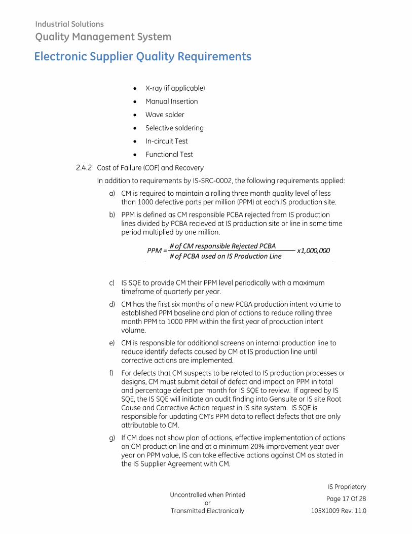
b) PPM is defined as CM responsible PCBA rejected from IS production lines divided by PCBA recieved at IS production site or line in same time period multiplied by one million.
c) IS SQE to provide CM their PPM level periodically with a maximum timeframe of quarterly per year.
d) CM has the first six months of a new PCBA production intent volume to established PPM baseline and plan of actions to reduce rolling three month PPM to 1000 PPM within the first year of production intent volume.
e) CM is responsible for additional screens on internal production line to reduce identify defects caused by CM at IS production line until corrective actions are implemented.
f) For defects that CM suspects to be related to IS production processes or designs, CM must submit detail of defect and impact on PPM in total and percentage defect per month for IS SQE to review. If agreed by IS SQE, the IS SQE will initiate an audit finding into Gensuite or IS site Root Cause and Corrective Action request in IS site system. IS SQE is responsible for updating CM’s PPM data to reflect defects that are only attributable to CM.
g) If CM does not show plan of actions, effective implementation of actions on CM production line and at a minimum 20% improvement year over year on PPM value, IS can take effective actions against CM as stated in the IS Supplier Agreement with CM.
# of CM responsible Rejected PCBA
# of PCBA used on IS Production LinePPM = x1,000,000
Industrial Solutions
Quality Management System
Electronic Supplier Quality Requirements
Uncontrolled when Printed or
Transmitted Electronically
IS Proprietary
Page 18 Of 28
105X1009 Rev: 11.0
h) CM internal quality targets at critical process steps listed below must support the 1000 PPM IS target. Internal quality targets must be reviewed at a maximum every 3 months to demonstrate continuous improvement.
• Paste Printing
• Placement
• Reflow
• AOI (if applicable).
• X-ray (if applicable)
• Manual Insertion
• Wave solder
• Selective soldering
• In-circuit Test
• Functional Test
i) CM has the first six months of a new PCBA production intent volume to established First Pass Yield baseline of 95% for each critical process step and plan of actions to improve First Pass Yield within the first year of production intent volume to 97%.
j) Each year, the CM and IS SQE will review first pass yield data and established first pass yield goal for each process for each of the IS Production sites.
2.4.3 Root Cause Analysis (RCA)/Corrective Action and Preventative Action (CAPA)
In addition to requirements by IS-SRC-0002, the following requirements applied:
a) The CM is required to have a well implemented Return Material Authorization (RMA) system in order to approve and track rejected material returns from Industrial Solutions. CM is responsible for shipping and analysis (laboratory) expenses for all rejects being returned for failure analysis on confirmed rejects. The CM must provide the return procedure for IS to follow to ensure tracking of all failures.
b) The CM is required to have a defined and working failure analysis and corrective action system. Failures identified at IS manufacturing facilities will be returned to the CM for analysis and corrective action. Each failure returned to CM or agreed to have repaired must be tracked, analyzed, and have a corrective action implemented before closing the report.
c) Failure analysis laboratory must have adequate equipment to perform:
Industrial Solutions
Quality Management System
Electronic Supplier Quality Requirements
Uncontrolled when Printed or
Transmitted Electronically
IS Proprietary
Page 19 Of 28
105X1009 Rev: 11.0
• Autopsy Analysis Level 1: To confirm that the suspect PCBA is defective.
• Autopsy Analysis Level 2: To confirm which component or process is causing the assembly to be defective.
d) In case of subtier supplier quality issue, CM must send defective components to subtier supplier or 3rd party external laboratory if failure rate is above one percent (1%) of total failure returned in RMA shipment for:
• Autopsy Analysis Level 3: To confirm root cause of component malfunction.
2.4.4 Production Reliability Audit Testing (PRAT)
Production Reliability Audits Testing Specification requirements must be followed in cases where IS requests per the drawing. Test methods and detailed specifications of PRAT testing will be provided by IS Engineering team in charge of the project.
2.4.5 Production Cleanliness Audit Testing
Bare PCB Ionic Chromatography or C3 Test cleanliness report is required on each PCB shipment lot to CM and results archived by CM for minimum three years.
Daily PCBA production cleanliness audit testing is required using Ionic Chromatography, Resistivity of Solvent Extract (ROSE), or C3 testing per build or work order, at minimum every four hours or once per production build if less than eight hours.
Quarterly Ionic Chromatography testing is required by the PCBA CM at a IS approved laboratory site. In cases where there are multiple part families, alternate samples from varying part families each quarter, so that all part families are tested at a minimum annually with an equal number of samples each quarter. Part Families are defined as having the same IS PCB part number. If CM is currently Ionic Chromatography testing or C3 testing for daily cleanliness monitoring on a part family, quarterly auditing monitoring is not required.
This must be documented in the part Product Quality Plan for the production of PCBA family and approved by IS SQE during qualification.
a) One (1) Processed PCB per part family from PCBA CM, run through each soldering processes and after wash process if applicable without conformal coating
b) Whole bag extraction for Ionic Chromatography test procedure is defined per IPC-TM-650 2.3.28.
Industrial Solutions
Quality Management System
Electronic Supplier Quality Requirements
Uncontrolled when Printed or
Transmitted Electronically
IS Proprietary
Page 20 Of 28
105X1009 Rev: 11.0
c) Localized extraction at three (3) locations or less, for Ionic Chromatography can be performed using the C3 tester equipment as per Foresite C3 operation manual to secure test solution. Test solution will be process per Ionic Chromatography test procedure as defined per IPC-TM-650 2.3.28.
d) The ROSE methods are fully described in IPC-TM-650 2.3.25.
e) C3 test procedure is defined per Foresite operation manual at three (3) locations or less, as agreed upon by IS SQE.
f) Ionic Chromatography, ROSE, and C3 limitation level are defined and test results analysis is define in section 2.5.
Industrial Solutions
Quality Management System
Electronic Supplier Quality Requirements
Uncontrolled when Printed or
Transmitted Electronically
IS Proprietary
Page 21 Of 28
105X1009 Rev: 11.0
2.5 Cleanliness
2.5.1 Purpose
Ionic contamination concerns IS due to the relationship between high contamination levels and failure of the printed circuit board due to electromigration. This section outlines IS Power Printed Circuit Board Assembly (PCBA) Cleanliness testing requirements, PCB/PCBA sample testing to be conducted, the data collection procedure, the method of analysis, definition of specification limits of each ion of concern and direction on action to take when levels are exceeded. In the event of conflict between the requirements of this document and the referenced applicable documents listed below, this document governs and takes precedence. This test is required when starting a new assembly line, switching to a new printed circuit board supplier, changing a PCBA supplier process or materials, or moving to a new contract manufacturer.
2.5.2 Approved laboratories
Foresite
1982 S. Elizabeth St. Kokomo IN 46902
(765) 457-8095 FAX (765) 457-9033 www.Residues.com
2.5.3 Test Results Analysis
Analysis of the Ionic Chromatography report as conducted by the Qualification team and/or CM. In case the average ionic values of individual ion of tested boards exceed the max limit for a given region or whole board of the PCBA, and/or any individual ionic value exceed 1.5x the max limit of a particular ion, and/or the WOA values exceed the limits in the below table (table 1):
• If qualifying a new PCB Manufacturer or a new PCBA Contact Manufacturer or a process/material change at current CM, then the qualification is rejected. Status is rejected until corrective action is implemented and proven effective through subsequent testing.
• If during audit testing of current production, then the production lots of printed circuit boards associated with the failed board must be placed into non-conforming material. Two additional boards must be selected from affected lot and tested. If both boards pass, lot is released. If another failure is
Industrial Solutions
Quality Management System
Electronic Supplier Quality Requirements
Uncontrolled when Printed or
Transmitted Electronically
IS Proprietary
Page 22 Of 28
105X1009 Rev: 11.0
observed, CM must follow Supplier Deviation process for IS disposition.
Analysis of the C3 report as conducted by the Qualification team and/or CM. In case the individual reading is above 250uA @ 120 seconds:
• If taken during qualifying a new PCB Manufacturer or a new PCBA Contact Manufacturer or a process/material change at current CM, then the C3 sample is recommend to be sent for Ionic Chromatography testing to understand potential cause of test result. C3 testing during qualification is recommended for the development of processes at CM. Ionic Chromatography is the needed for qualification unless approved by IS Supplier Quality Engineer.
• If during audit testing of current product, then the production lots of printed circuit boards associated with the failed board must be placed into non-conforming material. Two additional boards must be selected from affected lot and tested. If both boards pass, lot is released. If another failure is observed, CM must follow Supplier Deviation process for IS disposition and C3 sample is to be sent for Ionic Chromatography testing to understand potential cause of test results.
Analysis of the ROSE report as conducted by the Qualification team and/or CM. In case the individual reading is above 5ug/in2:
• If taken during qualifying a new PCB Manufacturer or a new PCBA Contact Manufacturer or a process/material change at current CM, then a lot sample is recommend to be sent for Ionic Chromatography testing to understand potential cause of test result. ROSE testing during qualification is recommended for only for the development of processes at CM. ROSE testing is not sufficient for qualification approval of process cleanliness level, Ionic Chromatography is needed for qualification.
• If during audit testing of current product, then the production lots of printed circuit boards associated with the failed board must be placed into non-conforming material. Two additional boards must be selected from affected lot and tested. If both boards pass, lot is released. If another failure is observed, CM must follow Supplier Deviation process for IS disposition and lot sample is to be sent for C3 and Ionic Chromatography testing to understand potential cause of test results.
Industrial Solutions
Quality Management System
Electronic Supplier Quality Requirements
Uncontrolled when Printed or
Transmitted Electronically
IS Proprietary
Page 23 Of 28
105X1009 Rev: 11.0
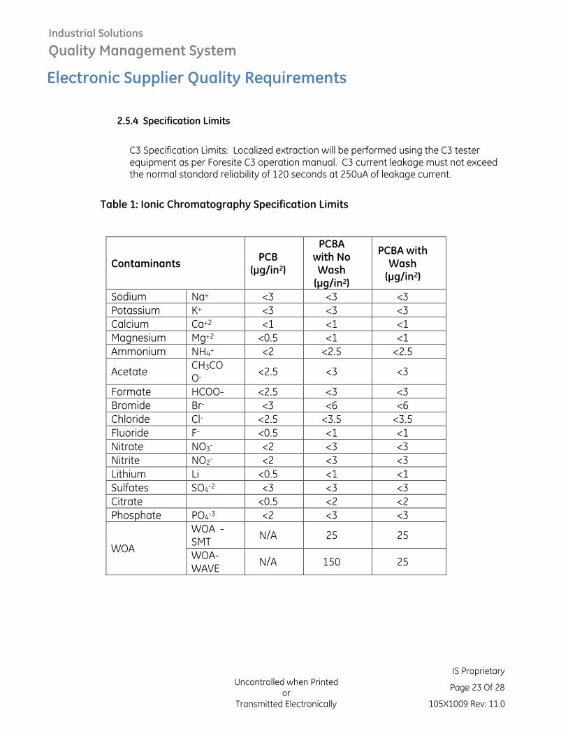
2.5.4 Specification Limits
C3 Specification Limits: Localized extraction will be performed using the C3 tester equipment as per Foresite C3 operation manual. C3 current leakage must not exceed the normal standard reliability of 120 seconds at 250uA of leakage current.
Table 1: Ionic Chromatography Specification Limits
Contaminants PCB
(μg/in2)
PCBA with No Wash (μg/in2)
PCBA with Wash (μg/in2)
Sodium Na+ <3 <3 <3
Potassium K+ <3 <3 <3
Calcium Ca+2 <1 <1 <1
Magnesium Mg+2 <0.5 <1 <1
Ammonium NH4+ <2 <2.5 <2.5
Acetate CH3COO-
<2.5 <3 <3
Formate HCOO- <2.5 <3 <3
Bromide Br- <3 <6 <6
Chloride Cl- <2.5 <3.5 <3.5
Fluoride F- <0.5 <1 <1
Nitrate NO3- <2 <3 <3
Nitrite NO2- <2 <3 <3
Lithium Li <0.5 <1 <1
Sulfates SO4-2 <3 <3 <3
Citrate <0.5 <2 <2
Phosphate PO4-3 <2 <3 <3
WOA
WOA - SMT
N/A 25 25
WOA-WAVE
N/A 150 25
Industrial Solutions
Quality Management System
Electronic Supplier Quality Requirements
Uncontrolled when Printed or
Transmitted Electronically
IS Proprietary
Page 24 Of 28
105X1009 Rev: 11.0
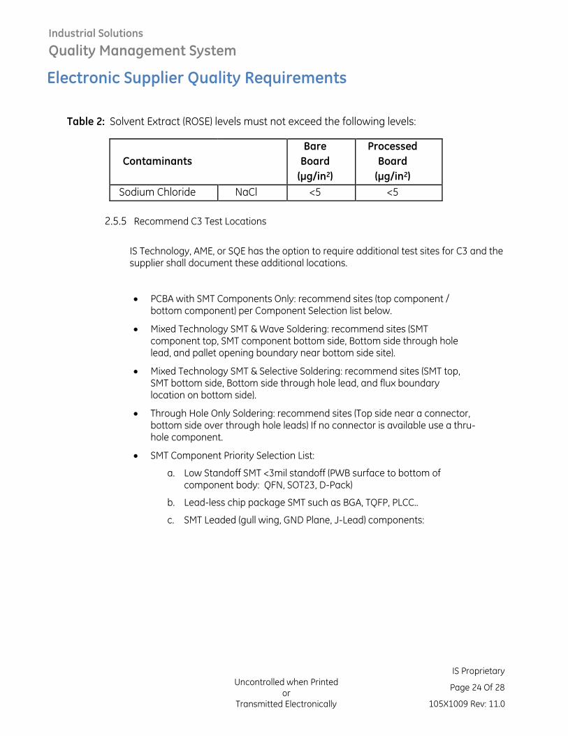
Table 2: Solvent Extract (ROSE) levels must not exceed the following levels:
2.5.5 Recommend C3 Test Locations
IS Technology, AME, or SQE has the option to require additional test sites for C3 and the supplier shall document these additional locations.
• PCBA with SMT Components Only: recommend sites (top component / bottom component) per Component Selection list below.
• Mixed Technology SMT & Wave Soldering: recommend sites (SMT component top, SMT component bottom side, Bottom side through hole lead, and pallet opening boundary near bottom side site).
• Mixed Technology SMT & Selective Soldering: recommend sites (SMT top, SMT bottom side, Bottom side through hole lead, and flux boundary location on bottom side).
• Through Hole Only Soldering: recommend sites (Top side near a connector, bottom side over through hole leads) If no connector is available use a thru-hole component.
• SMT Component Priority Selection List:
a. Low Standoff SMT <3mil standoff (PWB surface to bottom of component body: QFN, SOT23, D-Pack)
b. Lead-less chip package SMT such as BGA, TQFP, PLCC..
c. SMT Leaded (gull wing, GND Plane, J-Lead) components:
Contaminants
Bare
Board
(μg/in2)
Processed
Board
(μg/in2)
Sodium Chloride NaCl <5 <5
Industrial Solutions
Quality Management System
Electronic Supplier Quality Requirements
Uncontrolled when Printed or
Transmitted Electronically
IS Proprietary
Page 25 Of 28
105X1009 Rev: 11.0
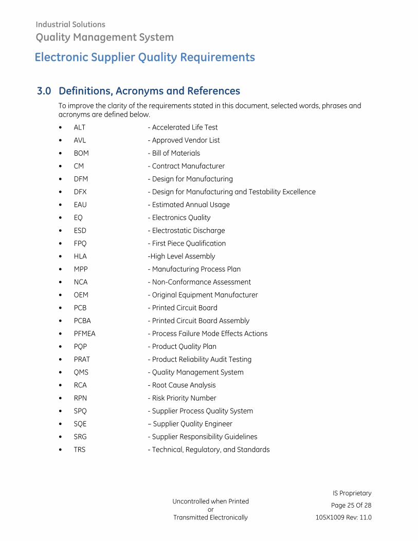
3.0 Definitions, Acronyms and References
To improve the clarity of the requirements stated in this document, selected words, phrases and acronyms are defined below.
• ALT - Accelerated Life Test
• AVL - Approved Vendor List
• BOM - Bill of Materials
• CM - Contract Manufacturer
• DFM - Design for Manufacturing
• DFX - Design for Manufacturing and Testability Excellence
• EAU - Estimated Annual Usage
• EQ - Electronics Quality
• ESD - Electrostatic Discharge
• FPQ - First Piece Qualification
• HLA -High Level Assembly
• MPP - Manufacturing Process Plan
• NCA - Non-Conformance Assessment
• OEM - Original Equipment Manufacturer
• PCB - Printed Circuit Board
• PCBA - Printed Circuit Board Assembly
• PFMEA - Process Failure Mode Effects Actions
• PQP - Product Quality Plan
• PRAT - Product Reliability Audit Testing
• QMS - Quality Management System
• RCA - Root Cause Analysis
• RPN - Risk Priority Number
• SPQ - Supplier Process Quality System
• SQE – Supplier Quality Engineer
• SRG - Supplier Responsibility Guidelines
• TRS - Technical, Regulatory, and Standards
Industrial Solutions
Quality Management System
Electronic Supplier Quality Requirements
Uncontrolled when Printed or
Transmitted Electronically
IS Proprietary
Page 26 Of 28
105X1009 Rev: 11.0
• Traceability – The ability to determine the history, location, application, processing conditions and/or composition of a product by means of documented recorded identification.
• Record – Document stating achieved results or providing evidence of performed activities.
• Audit – Independent review and examination of records and activities to assess the adequacy of system controls, to ensure compliance with established policies and operational procedures, and to identify deficiencies in controls, policies or procedures for corrective and preventive action.
• Audit Criteria – Set of policies, procedures, work instruction or requirement used as a reference.
• Audit Finding – Result of the evaluation of the collected audit evidence against audit criteria. Audit findings can indicate either conformance or nonconformance with audit criteria or opportunities for improvement.
• Containment – Actions taken to minimize Industrial Solutions and customer risk associated with a nonconformance. Containment actions apply to product, process or material in which the nonconformance was detected as well as similar products or product families in which the nonconformance may occur.
• Continuous Improvement – Recurring activity to increase the ability to fulfill requirements. The process of establishing objectives and finding opportunities for improvement is a continuous process.
• Correction – Actions to repair rework or replace the detected nonconformance, defect or other non-desirable situation.
• Corrective Action – Action taken to eliminate the cause(s) of an existing nonconformance, defect or other non-desirable situation to prevent recurrence.
• Procedure – Documented statement of QMS process requirements. Unlike a Work Instruction, a procedure does not state how the process must be performed.
• Process – Set of interrelated activities which transform inputs into outputs.
• Product – The result of a process. Whenever the term “product” occurs, it can also mean “service”, or any deliverable associated with fulfillment of a contract.
• Quality Management System – Management system to direct and control an organization with regard to quality.
• Requirement – Need or expectation that is stated, generally implied or obligatory.
• Root Cause – A cause of an incident, which, if it had not occurred, would have prevented the incident.
Through this document the term Contract Manufacturer (CM) and the term Supplier are used indistinctively and are considered of equivalent meaning.
Industrial Solutions
Quality Management System
Electronic Supplier Quality Requirements
Uncontrolled when Printed or
Transmitted Electronically
IS Proprietary
Page 27 Of 28
105X1009 Rev: 11.0
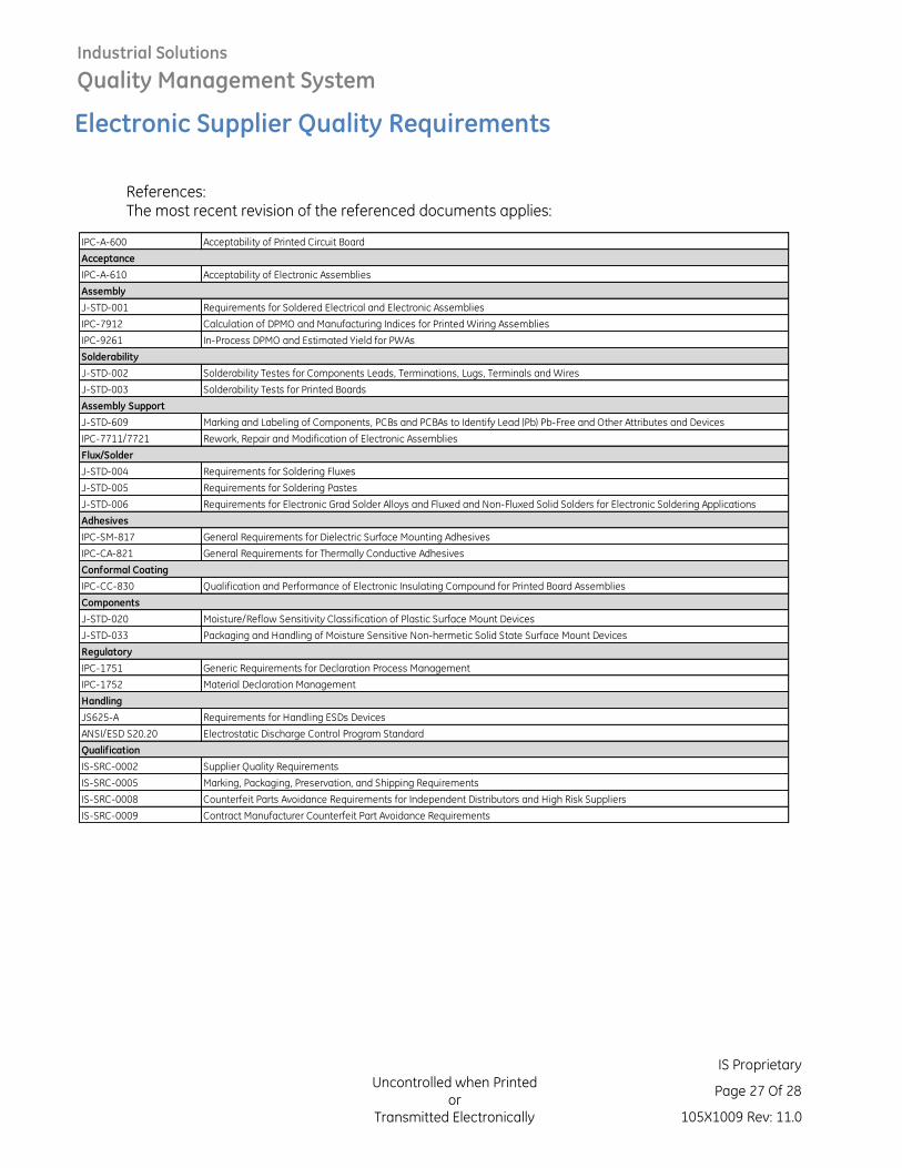
References: The most recent revision of the referenced documents applies:
IPC-A-600 Acceptability of Printed Circuit Board
IPC-A-610 Acceptability of Electronic Assemblies
J-STD-001 Requirements for Soldered Electrical and Electronic Assemblies
IPC-7912 Calculation of DPMO and Manufacturing Indices for Printed Wiring Assemblies
IPC-9261 In-Process DPMO and Estimated Yield for PWAs
J-STD-002 Solderability Testes for Components Leads, Terminations, Lugs, Terminals and Wires
J-STD-003 Solderability Tests for Printed Boards
J-STD-609 Marking and Labeling of Components, PCBs and PCBAs to Identify Lead (Pb) Pb-Free and Other Attributes and Devices
IPC-7711/7721 Rework, Repair and Modification of Electronic Assemblies
J-STD-004 Requirements for Soldering Fluxes
J-STD-005 Requirements for Soldering Pastes
J-STD-006 Requirements for Electronic Grad Solder Alloys and Fluxed and Non-Fluxed Solid Solders for Electronic Soldering Applications
IPC-SM-817 General Requirements for Dielectric Surface Mounting Adhesives
IPC-CA-821 General Requirements for Thermally Conductive Adhesives
IPC-CC-830 Qualification and Performance of Electronic Insulating Compound for Printed Board Assemblies
J-STD-020 Moisture/Reflow Sensitivity Classification of Plastic Surface Mount Devices
J-STD-033 Packaging and Handling of Moisture Sensitive Non-hermetic Solid State Surface Mount Devices
IPC-1751 Generic Requirements for Declaration Process Management
IPC-1752 Material Declaration Management
JS625-A Requirements for Handling ESDs Devices
ANSI/ESD S20.20 Electrostatic Discharge Control Program Standard
IS-SRC-0002 Supplier Quality Requirements
IS-SRC-0005 Marking, Packaging, Preservation, and Shipping Requirements
IS-SRC-0008 Counterfeit Parts Avoidance Requirements for Independent Distributors and High Risk Suppliers
IS-SRC-0009 Contract Manufacturer Counterfeit Part Avoidance Requirements
Flux/Solder
Assembly Support
Acceptance
Assembly
Solderability
Qualification
Adhesives
Conformal Coating
Components
Regulatory
Handling
Industrial Solutions
Quality Management System
Electronic Supplier Quality Requirements
Uncontrolled when Printed or
Transmitted Electronically
IS Proprietary
Page 28 Of 28
105X1009 Rev: 11.0
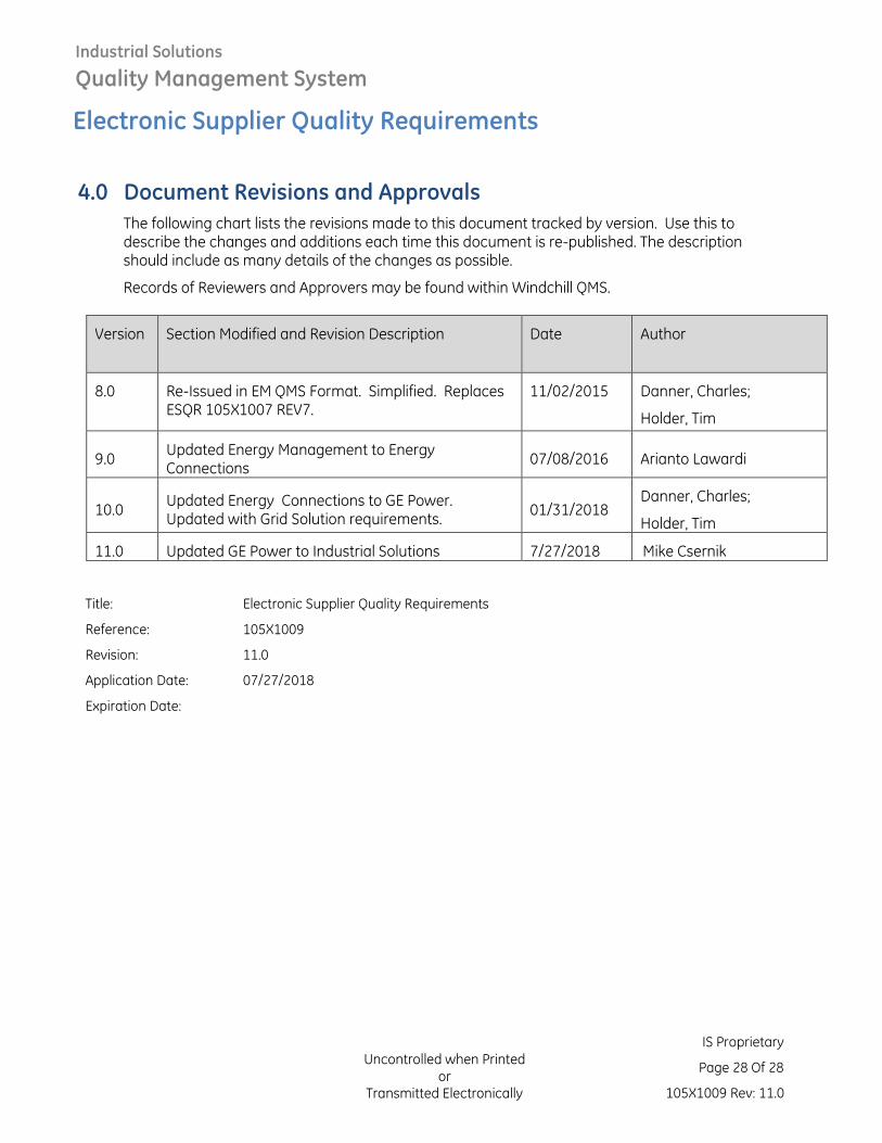
4.0 Document Revisions and Approvals
The following chart lists the revisions made to this document tracked by version. Use this to describe the changes and additions each time this document is re-published. The description should include as many details of the changes as possible.
Records of Reviewers and Approvers may be found within Windchill QMS.
Version Section Modified and Revision Description Date Author
8.0 Re-Issued in EM QMS Format. Simplified. Replaces ESQR 105X1007 REV7.
11/02/2015 Danner, Charles;
Holder, Tim
9.0 Updated Energy Management to Energy Connections
07/08/2016 Arianto Lawardi
10.0 Updated Energy Connections to GE Power. Updated with Grid Solution requirements.
01/31/2018 Danner, Charles;
Holder, Tim
11.0 Updated GE Power to Industrial Solutions 7/27/2018 Mike Csernik
Title:
Electronic Supplier Quality Requirements
Reference: 105X1009
Revision: 11.0
Application Date: 07/27/2018
Expiration Date: