
Electronic Supplementary Information For: Absorption · PDF fileElectronic Supplementary...
7
S1 Electronic Supplementary Information For: High-Performance Ternary Blend All-Polymer Solar Cells with Complementary Absorption Bands from Visible to Near-Infrared Wavelengths Hiroaki Benten, Takaya Nishida, Daisuke Mori, Huajun Xu, Hideo Ohkita, and Shinzaburo Ito Department of Polymer Chemistry, Graduate School of Engineering, Kyoto University, Katsura, Nishikyo, Kyoto 615-8510, Japan E-mail: [email protected]; [email protected] Experimental Details Materials: The polymers PBDTTT-EF-T, N2200, and PCDTBT were obtained from 1- Material Inc., Polyera Corporation, and Ossila, respectively, and used as received. The weight-average molecular weight M w , and polydispersity index (PDI), (given by M w /M n , where M n is the number-average molecular weight) of the polymers as provided on the Certificate of Analysis were 121,000 g mol -1 and 2.4 for PBDTTT-EF-T; 84,300 g mol -1 and 3.1 for N2200; and 42,200 g mol -1 and 2.15 for PCDTBT. The HOMO levels of the polymer neat films were determined by photoelectron yield spectroscopy (Riken Keiki, AC-3). To accurately evaluate the HOMO levels, the bottom surfaces of the neat films were measured. Their LUMO levels were estimated by adding the optical bandgap energy (E g ), calculated from the 0-0 transition, to the HOMO energy; E g was calculated as 1.68 eV (PBDTTT-EF-T), 1.55 eV (N2200), and 1.95 eV (PCDTBT) by using E g = hc/λ 0-0 , where h is Planck’s constant, c is the velocity of light, and λ 0-0 is the wavelength of the crossing point between the absorption and PL bands of the neat films (Figure S1). Device Fabrication and Measurements: Indium-tin-oxide-coated (ITO-coated) glass substrates (10 Ω per square) were washed by ultrasonication with toluene, then acetone, and finally ethanol for 15 min each and dried under N 2 flow. The washed substrates were further treated with a UV–O 3 cleaner (Nippon Laser & Electronics Lab., NL-UV253S) for 30 min. A 40-nm topcoat layer of poly(3,4-ethylenedioxythiophene):poly(4-styrenesulfonate) (PEDOT:PSS; H.C. Stark PH-500) was spin-coated onto the ITO substrate at a spin rate of 3000 rotations per minute (rpm) for 99 s and then dried in air at 140 °C for 10 min. The PBDTTT-EF-T/N2200 binary and PBDTTT-EF-T/N2200/PCDTBT ternary blend films were Electronic Supplementary Material (ESI) for Energy & Environmental Science. This journal is © The Royal Society of Chemistry 2015
Transcript of Electronic Supplementary Information For: Absorption · PDF fileElectronic Supplementary...
S1
Electronic Supplementary Information For: High-Performance Ternary Blend All-Polymer Solar Cells with Complementary Absorption Bands from Visible to Near-Infrared Wavelengths Hiroaki Benten, Takaya Nishida, Daisuke Mori, Huajun Xu, Hideo Ohkita, and Shinzaburo Ito Department of Polymer Chemistry, Graduate School of Engineering, Kyoto University, Katsura, Nishikyo, Kyoto 615-8510, Japan E-mail: [email protected]; [email protected]
Experimental Details
Materials: The polymers PBDTTT-EF-T, N2200, and PCDTBT were obtained from 1-
Material Inc., Polyera Corporation, and Ossila, respectively, and used as received. The
weight-average molecular weight Mw, and polydispersity index (PDI), (given by Mw/Mn,
where Mn is the number-average molecular weight) of the polymers as provided on the
Certificate of Analysis were 121,000 g mol−1 and 2.4 for PBDTTT-EF-T; 84,300 g mol−1 and
3.1 for N2200; and 42,200 g mol−1 and 2.15 for PCDTBT. The HOMO levels of the polymer
neat films were determined by photoelectron yield spectroscopy (Riken Keiki, AC-3). To
accurately evaluate the HOMO levels, the bottom surfaces of the neat films were measured.
Their LUMO levels were estimated by adding the optical bandgap energy (Eg), calculated
from the 0−0 transition, to the HOMO energy; Eg was calculated as 1.68 eV (PBDTTT-EF-T),
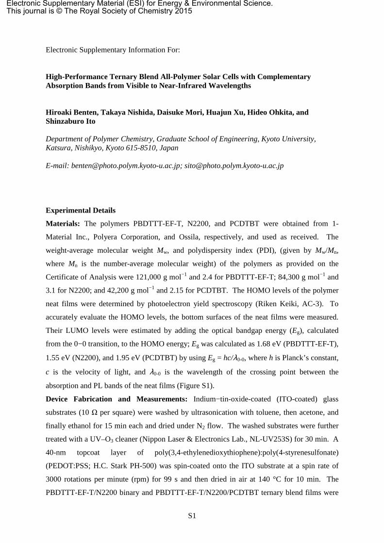
1.55 eV (N2200), and 1.95 eV (PCDTBT) by using Eg = hc/λ0-0, where h is Planck’s constant,
c is the velocity of light, and λ0-0 is the wavelength of the crossing point between the
absorption and PL bands of the neat films (Figure S1).
Device Fabrication and Measurements: Indium−tin-oxide-coated (ITO-coated) glass
substrates (10 Ω per square) were washed by ultrasonication with toluene, then acetone, and
finally ethanol for 15 min each and dried under N2 flow. The washed substrates were further
treated with a UV–O3 cleaner (Nippon Laser & Electronics Lab., NL-UV253S) for 30 min. A
40-nm topcoat layer of poly(3,4-ethylenedioxythiophene):poly(4-styrenesulfonate)
(PEDOT:PSS; H.C. Stark PH-500) was spin-coated onto the ITO substrate at a spin rate of
3000 rotations per minute (rpm) for 99 s and then dried in air at 140 °C for 10 min. The
PBDTTT-EF-T/N2200 binary and PBDTTT-EF-T/N2200/PCDTBT ternary blend films were
Electronic Supplementary Material (ESI) for Energy & Environmental Science.This journal is © The Royal Society of Chemistry 2015

S2
prepared by spin-coating from chlorobenzene solutions onto the PEDOT:PSS films. The
solution for the binary blend film was prepared by mixing PBDTTT-EF-T and N2200 at a 1:1
weight ratio in chlorobenzene; (PBDTTT-EF-T (9 mg) and N2200 (9 mg) were dissolved in 1
mL of chlorobenzene). PCDTBT was added to the binary blend solution, such that the weight
fraction of PCDTBT in the ternary blend films ranged from 0 to 30 wt.%. The spin rate of
these solutions was adjusted, so that the absorbance of the ternary blend films at wavelengths
longer than 670 nm had the same value as that of the PBDTTT-EF-T/N2200 binary blend film.
The PCDTBT/N2200 binary blend and PBDTTT-EF-T/PCDTBT binary blend films were
also prepared by spin-coating from chlorobenzene solutions onto the PEDOT:PSS films. The
weight ratio of PCDTBT to N2200 was 1:1; [PCDTBT (9 mg) and N2200 (9 mg) were
dissolved in 1 mL of chlorobenzene]. The weight ratio of PBDTTT-EF-T to PCDTBT was
1:1; [PBDTTT-EF-T (9 mg) and PCDTBT (9 mg) were dissolved in 1 mL of chlorobenzene].
Preparation of the chlorobenzene solutions and the subsequent spin-coating procedure were
carried out in an N2-filled glove box. Finally, a 3-nm calcium interlayer and a 70-nm
aluminium electrode were vacuum-deposited through a shadow mask at a pressure of 2.5 ×
10−4 Pa. The area of the circular Ca/Al electrode was 0.07 cm2. The J–V characteristics and
EQE spectra of the devices were measured using an ECT-250D integrated system made by
Bunkoukeiki Co., Ltd. The light intensity for J–V measurements was corrected with a
calibrated silicon photodiode reference cell (Bunkoukeiki, BS-520), whose active area was
0.0534 cm2. The EQE spectra were measured under the illumination of monochromatic light
from a 300 W xenon lamp with optical cut filters and a double monochromator. The power of
the incident monochromatic light was kept under 0.05 mW cm−2, as measured by a calibrated
silicon reference cell. The active area of the device was 0.07 cm2, which was determined
from the area of the top Ca/Al electrode. All the measurements were carried out under an N2
atmosphere at room temperature.
Mobility Measurements: Hole-only devices were fabricated using the following procedure:
PBDTTT-EF-T/N2200 binary and PBDTTT-EF-T/N2200/PCDTBT ternary blend layers were
spin-coated onto separate ITO substrates covered with 40-nm of PEDOT:PSS, which acted as
the anode. A 40-nm gold electrode was then vacuum-deposited on each layer
(ITO|PEDOT:PSS|PBDTTT-EF-T/N2200|Au and ITO|PEDOT:PSS|PBDTTT-EF-
T/N2200/PCDTBT|Au). Electron-only devices were fabricated by the following procedure: A
50-nm Al layer was vacuum-deposited on a glass substrate covered with 20-nm of
poly(sodium 4-styrenesulfonate) (PSS, Mw = 70,000 g mol−1) film. PBDTTT-EF-T/N2200
binary and PBDTTT-EF-T/N2200/PCDTBT ternary blend layers were spin-coated onto each
S3
Al electrode under the same conditions used for device fabrication. A 4-nm Cs2CO3
interlayer and an 80-nm Al layer were then vacuum-deposited as the cathodes (Al|PBDTTT-
EF-T/N2200|Cs2CO3|Al and Al|PBDTTT-EF-T/N2200/PCDTBT|Cs2CO3|Al). The dark J–V
characteristics were measured in an N2 atmosphere using a direct-current voltage and a
current source/monitor (KEITHLEY, 2611B).
Photoluminescence Quenching Measurements: Neat and ternary blend films spin-coated
onto quartz substrates from chlorobenzene solutions were used as samples for the PL
quenching measurements. The PL spectra were measured using a calibrated fluorescence
spectrophotometer (Horiba, NanoLog). The ternary blend films were excited at 500 nm to
excite primarily the PCDTBT and PBDTTT-EF-T components and at 400 nm to excite
primarily the PCDTBT and N2200 components. To estimate the degree of PL quenching, the
PL intensity of each component in the ternary blends was compared to that of PCDTBT,
PBDTTT-EF-T, and N2200 neat films (after the PL intensity of each neat film was corrected
for variations in PCDTBT and PBDTTT-EF-T absorptions at 500 nm and PCDTBT and
N2200 absorptions at 400 nm in the ternary blend films).
1. Calculation of the Optical Bandgap Energy (Eg)
Figure. S1. Absorbance (solid lines) and PL (dashed lines) spectra of (a) PCDTBT, (b)
PBDTTT-EF-T, and (c) N2200 neat films spin-coated from chlorobenzene solution. The
optical bandgap energy (Eg) was calculated from the 0-0 transition using Eg = hc/λ0-0, where h
is Planck’s constant, c is the velocity of light, and λ0-0 is the wavelength of the crossing point
between the absorption and PL bands.
S4
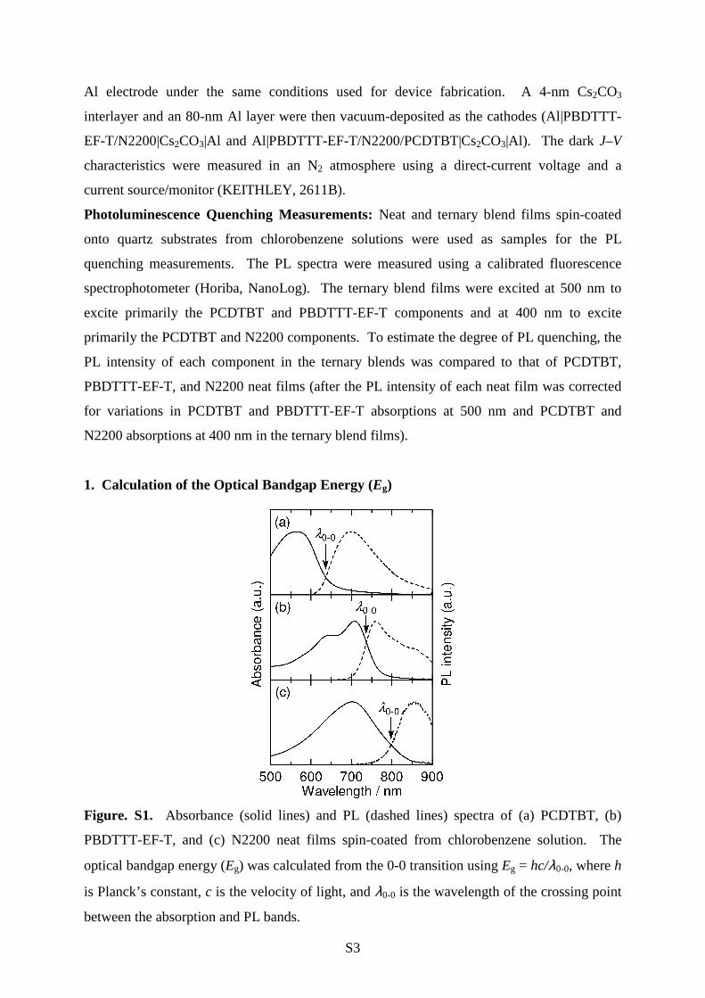
2. Device Performance of a PBDTTT-EF-T/PCDTBT Binary BHJ Solar Cell
Figure. S2. J–V characteristics of a PBDTTT-EF-T/PCDTBT binary BHJ solar cell
measured under AM1.5G illumination from a calibrated solar simulator with an intensity of
100 mW cm–2. The broken line represents the J–V characteristics under dark conditions. The
photovoltaic parameters were JSC = 0.118 mA cm–2, VOC = 1.23 V, FF = 0.287, and PCE =
0.042%.
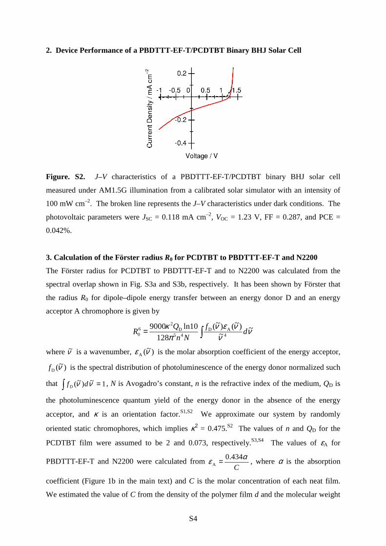
3. Calculation of the Förster radius R0 for PCDTBT to PBDTTT-EF-T and N2200
The Förster radius for PCDTBT to PBDTTT-EF-T and to N2200 was calculated from the
spectral overlap shown in Fig. S3a and S3b, respectively. It has been shown by Förster that
the radius R0 for dipole–dipole energy transfer between an energy donor D and an energy
acceptor A chromophore is given by
∫= νν
νενπ
κ ~~
)~()~(
128
10ln90004
AD45
D2
60 d
f
Nn
QR
where ν~ is a wavenumber, )~(A νε is the molar absorption coefficient of the energy acceptor,
)~(D νf is the spectral distribution of photoluminescence of the energy donor normalized such
that 1~)~(D =∫ νν df , N is Avogadro’s constant, n is the refractive index of the medium, QD is
the photoluminescence quantum yield of the energy donor in the absence of the energy
acceptor, and κ is an orientation factor.S1,S2 We approximate our system by randomly
oriented static chromophores, which implies κ2 = 0.475.S2 The values of n and QD for the
PCDTBT film were assumed to be 2 and 0.073, respectively.S3,S4 The values of εA for
PBDTTT-EF-T and N2200 were calculated from C
αε 434.0A = , where α is the absorption
coefficient (Figure 1b in the main text) and C is the molar concentration of each neat film.
We estimated the value of C from the density of the polymer film d and the molecular weight
S5
of the monomer unit M, using 310
1−×=
M
dC . Here, we assumed d to be 1.0 g cm–3 for both
films, and M was 907.4 g mol–1 for PBDTTT-EF-T and 991.5 g mol–1 for N2200.
Figure S3. Estimated molar absorption coefficient εA of (a) PBDTTT-EF-T (broken line) and
(b) N2200 (broken line) neat film, and normalized PL spectrum of PCDTBT neat film (solid
line).
4. PL Quenching in the PBDTTT-EF-T/N2200/PCDTBT Ternary Blends
Figure S4. PL spectra of PBDTTT-EF-T/N2200/PCDTBT ternary blend films (solid lines)
that contained (a, d) 5 wt.%, (b, e) 20 wt.%, and (c, f) 30 wt.% of PCDTBT. The ternary
blend films were excited at (a, b, c) 400 nm to excite primarily the PCDTBT and N2200
components; and at (d, e, f) 500 nm to excite primarily the PCDTBT and PBDTTT-EF-T
components. The broken lines represent the PL spectra of PCDTBT neat film after its PL
intensity was corrected for variations in PCDTBT absorption at (a, b, c) 400 nm and at (d, e,
f) 500 nm in each ternary blend film.
S6
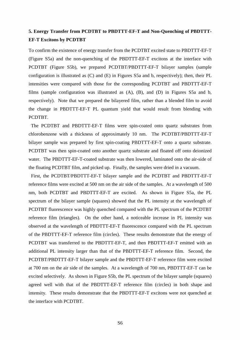
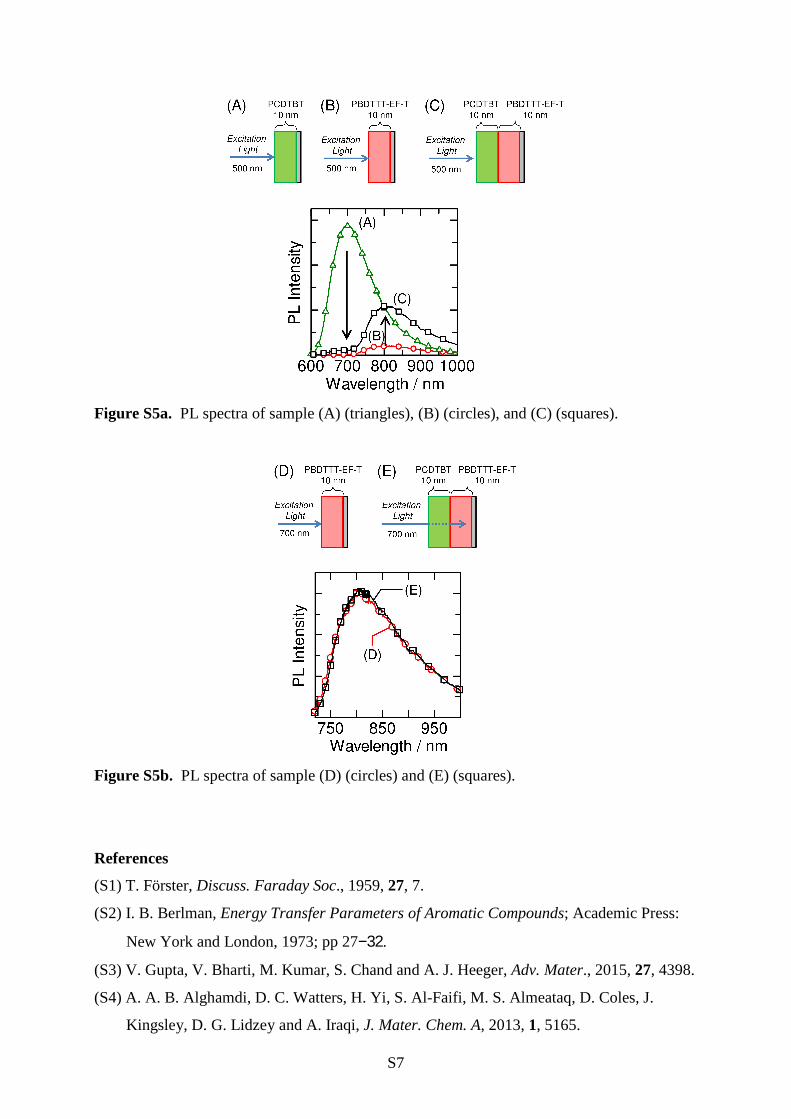
5. Energy Transfer from PCDTBT to PBDTTT-EF-T and Non-Quenching of PBDTTT-
EF-T Excitons by PCDTBT
To confirm the existence of energy transfer from the PCDTBT excited state to PBDTTT-EF-T
(Figure S5a) and the non-quenching of the PBDTTT-EF-T excitons at the interface with
PCDTBT (Figure S5b), we prepared PCDTBT/PBDTTT-EF-T bilayer samples (sample
configuration is illustrated as (C) and (E) in Figures S5a and b, respectively); then, their PL
intensities were compared with those for the corresponding PCDTBT and PBDTTT-EF-T
films (sample configuration was illustrated as (A), (B), and (D) in Figures S5a and b,
respectively). Note that we prepared the bilayered film, rather than a blended film to avoid
the change in PBDTTT-EF-T PL quantum yield that would result from blending with
PCDTBT.
The PCDTBT and PBDTTT-EF-T films were spin-coated onto quartz substrates from
chlorobenzene with a thickness of approximately 10 nm. The PCDTBT/PBDTTT-EF-T
bilayer sample was prepared by first spin-coating PBDTTT-EF-T onto a quartz substrate.
PCDTBT was then spin-coated onto another quartz substrate and floated off onto deionized
water. The PBDTTT-EF-T-coated substrate was then lowered, laminated onto the air-side of
the floating PCDTBT film, and picked up. Finally, the samples were dried in a vacuum.
First, the PCDTBT/PBDTTT-EF-T bilayer sample and the PCDTBT and PBDTTT-EF-T
reference films were excited at 500 nm on the air side of the samples. At a wavelength of 500
nm, both PCDTBT and PBDTTT-EF-T are excited. As shown in Figure S5a, the PL
spectrum of the bilayer sample (squares) showed that the PL intensity at the wavelength of
PCDTBT fluorescence was highly quenched compared with the PL spectrum of the PCDTBT
reference film (triangles). On the other hand, a noticeable increase in PL intensity was
observed at the wavelength of PBDTTT-EF-T fluorescence compared with the PL spectrum
of the PBDTTT-EF-T reference film (circles). These results demonstrate that the energy of
PCDTBT was transferred to the PBDTTT-EF-T, and then PBDTTT-EF-T emitted with an
additional PL intensity larger than that of the PBDTTT-EF-T reference film. Second, the
PCDTBT/PBDTTT-EF-T bilayer sample and the PBDTTT-EF-T reference film were excited
at 700 nm on the air side of the samples. At a wavelength of 700 nm, PBDTTT-EF-T can be
excited selectively. As shown in Figure S5b, the PL spectrum of the bilayer sample (squares)
agreed well with that of the PBDTTT-EF-T reference film (circles) in both shape and
intensity. These results demonstrate that the PBDTTT-EF-T excitons were not quenched at
the interface with PCDTBT.
S7
Figure S5a. PL spectra of sample (A) (triangles), (B) (circles), and (C) (squares).
Figure S5b. PL spectra of sample (D) (circles) and (E) (squares).
References
(S1) T. Förster, Discuss. Faraday Soc., 1959, 27, 7.
(S2) I. B. Berlman, Energy Transfer Parameters of Aromatic Compounds; Academic Press:
New York and London, 1973; pp 27−32.
(S3) V. Gupta, V. Bharti, M. Kumar, S. Chand and A. J. Heeger, Adv. Mater., 2015, 27, 4398.
(S4) A. A. B. Alghamdi, D. C. Watters, H. Yi, S. Al-Faifi, M. S. Almeataq, D. Coles, J.
Kingsley, D. G. Lidzey and A. Iraqi, J. Mater. Chem. A, 2013, 1, 5165.


![Chlorobenzene 153 EVALUATOR: Limited, Runcorn, England.COHPONENTS: Chlorobenzene EVALUATOR: 153 (1) Chlorobenzene; C 6 H 5 Cl; [108-90-7] (2) Water; H 2 0; [7732-18-5] CRITICAL EVALUATION:](https://static.fdocuments.in/doc/165x107/60bbadcfe12a7c75e30db330/chlorobenzene-153-evaluator-limited-runcorn-cohponents-chlorobenzene-evaluator.jpg)


