Electronic Pressure Switch EDS 3000img56.chem17.com/1/20140912/635461278512507717382.pdfElectronic...
17
For Your Information Electronic Pressure Switch EDS 3000 User Manual Revision: November 01, 2002 1. EDS 3000 Functions
Transcript of Electronic Pressure Switch EDS 3000img56.chem17.com/1/20140912/635461278512507717382.pdfElectronic...

For Your Information
Electronic Pressure Switch EDS 3000
User Manual
Revision: November 01, 2002
1. EDS 3000 Functions
User Manual EDS 3000
2
The EDS 3000 unit offers the following functions:
• Display pressure in psi, MPa, bar or a freely scalable range. • Display of the actual pressure, maximum measured pressure or a switching point.• Operation of the switching outputs according to the pressure and the adjusted switch-point
parameters or by using the window feature.• Depending on the model, the choice of selecting either a 4...20mA or 0...10VDC analog output
signal. • Menus for adjustment (adapting the EDS 3000 to a particular application).• Programming enables (lockouts).
4 different output versions are available:
• EDS 3000 with 1 switching output • EDS 3000 with 1 switching output and analog signal output• EDS 3000 with 2 switching outputs • EDS 3000 with 2 switching outputs and analog signal output
2. Mounting
The EDS 3000 can be mounted onto a hydraulic block via the G¼ form A (DIN 3852) externalthreaded pressure connection. After mounting, the EDS can be rotated for optimal adjustmentaround its longitudinal axis, additionally is possible to rotate the display for better viewing andaccess to the control keys. The electrical connections must be carried out by a qualified electricianaccording to applicable codes, laws or regulations that pertain to the location (VDE 0100 inGermany). The EDS housing must be grounded properly. When mounted to a hydraulic block, it issufficient if the block is grounded over the hydraulic system. When mounting by means of hose,the housing must be grounded separately.
Also try to follow these installation recommendations to reduce the effect of electromagneticinterference:
• Make electrical cable connections as short as possible.• Use shielded cable.• The shielded cable must be fitted by qualified personal using interference suppressing
techniques.• Direct proximity to other connection lines of units generating interference or the unit itself must
be avoided.

User Manual EDS 3000
3
3. EDS 3000 Display and User Interface
4-digit display
Keys for adjusting menu and switch points
SP1 SP2
HYDAC
mode
PSI MPa bar
4. Digital Display
After switching on the supply voltage, the EDS displays " EdS " briefly followed by the measuredpressure.
In the adjustment menu the display can be altered. For example, the maximum measuredpressure value can be permanently displayed. This is the highest measured value since the unitwas last switched on or reset. Pressing the or will reset the highest measured value. Also aswitching point value can be permanently displayed or the display can be set to dark. If set to dark,the measured pressure can be displayed briefly by pressing the or key. Depending on thesetting, “TOP”, “S.P. 1”, “S.P. 2 or oFF” will appear breifly in the display when the unit isswitched on informing the user what the display will show.
Notes
• If the applied pressure exceeds the measuring range of the EDS, it will no longer display the pressure and the display will begin to flash.
• If applied pressure is below 1% of the measuring range, then 0 is displayed.
2 s

User Manual EDS 3000
4
5. Output Functions
5.1 Switching Outputs
The EDS 3000 can have 1 or 2 switching outputs. The following settings can be made under theswitch-point and adjustments menu:
5.1.1 Switch point setting (SP)
One switch point and one hysteresis can be set for each switching output. The respective outputswitches when the user set switch point pressure value is reached and switches back when thepressure falls below the switchback point. The switchback point is calculated by subtracting thehysteresis value from the switching point value. (switch back point = switching point – hysteresis)
Abbreviations: "SP.1" or "SP.2" = switching point 1 or 2"HyS.1“ or "HyS.2" = hysteresis 1 or 2
5.1.2 Window Function Settings (WIN)
The window function enables a range of pressure to be monitored. For each switching output, anupper and a lower switching value can be set to determine the range. The respective outputswitches when the pressure enters this range. When the pressure leaves the range and the switchback value has been met, the output switches back. The lower switch back value is just below thelower switching value (lower switching value minus three times the increment, see point 5.4). Theupper switch back value is just above the upper switching value (upper switching value plus threetimes the increment, see point 5.4). The area between switching and switch back value forms asafety zone, which prevents unwanted switching operations from occurring (e.g. triggered bypulsation from a pump). Example of switching output 1 (normally open function):
Abbreviations: "HI 1" = High level 1 "Lo 1“ = Low level 1
Note: The window function only operates correctly (switching on and off) when all switching values (including the safety zone) are greater than 0 and are lower than the pressure measuring range.
Lo.1
hi.1 plus 3xincrement
Lo.1 minus 3xincrement
P
t
Safety zone
Safety zone
On
Off
Off
On
ON
Off
Switch-back valuetSwitching value
Switch-back valueSwitching value
hi.1
User Manual EDS 3000
5
5.2 Analog Output
On specified models, the EDS 3000 has a choice of 4...20mA or 0...10VDC sourcing signal outputwhich is selectable in the adjustment menu.
5.3 Setting the Switching Points and Hysteresis
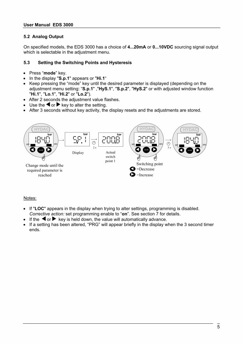
• Press “mode” key.• In the display "S.p.1" appears or "Hi.1“• Keep pressing the “mode” key until the desired parameter is displayed (depending on the
adjustment menu setting: “S.p.1" ,"HyS.1", "S.p.2", "HyS.2" or with adjusted window function"Hi.1", "Lo.1", "Hi.2" or "Lo.2").
• After 2 seconds the adjustment value flashes.• Use the or key to alter the setting.• After 3 seconds without key activity, the display resets and the adjustments are stored.
2 s 3 s
Change mode until the required parameter is
reached
Display
=Decrease
=Increase
SP1 SP2
HYDAC
mode
bar
SP1 SP2
HYDAC
mode
bar bar bar
SP1 SP2
HYDAC
mode
bar
Actual switch point 1
Switching point
Notes:
• If "LOC" appears in the display when trying to alter settings, programming is disabled. Corrective action: set programming enable to “on”. See section 7 for details.
• If the or key is held down, the value will automatically advance.• If a setting has been altered, “PRG” will appear briefly in the display when the 3 second timer
ends.

User Manual EDS 3000
6
5.4 Ranges of Adjustment for the Switching Outputs
Measuring rangein bar
Switching point orupper switching value
in bar
Hysteresis point orlower switching value
in bar
Increment *in bar
1 0.008 .. 1 0.006 .. 0.99 0.0022.5 0.02 .. 2.5 0.015 .. 2.47 0.0054 0.03 .. 4 0.02 .. 3.96 0.010
10 0.08 .. 10 0.06 .. 9.90 0.02016 0.15 .. 16 0.10 .. 15.85 0.05025 0.2 .. 25 0.15 .. 24.75 0.05040 0.3 .. 40 0.2 .. 39.60 0.10060 0.5 .. 60 0.3 .. 59.40 0.100
100 0.8 .. 100 0.6 .. 99.00 0.200250 2.0 .. 250 1.5 .. 247.50 0.500400 3.0 .. 400 2.0 .. 396.00 1.000600 5.0 .. 600 3.0 .. 594.00 1.000
* All areas indicated in the table are adjustable by the increments shown.
User Manual EDS 3000
7
6. Menu Adjustments
In order to adapt the unit to a particular application, the EDS 3000 can be altered via several menusettings.
6.1 Altering the Menu Settings
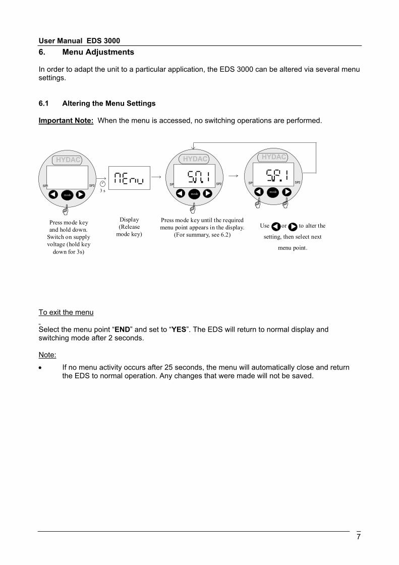
Important Note: When the menu is accessed, no switching operations are performed.
3 s
Display (Release
mode key)
Press mode key and hold down.
Switch on supply voltage (hold key
down for 3s)
Press mode key until the required menu point appears in the display.
(For summary, see 6.2)
SP1 SP2
HYDAC
mode
SP1 SP2
HYDAC
mode
SP1 SP2
HYDAC
mode
Use or to alter the
setting, then select next
menu point.
To exit the menu Select the menu point “END” and set to “YES”. The EDS will return to normal display andswitching mode after 2 seconds.
Note:• If no menu activity occurs after 25 seconds, the menu will automatically close and return
the EDS to normal operation. Any changes that were made will not be saved.
User Manual EDS 3000
8
6.2 Outline of the Adjustment Menu Points
Setting Point Display SettingChoices Factory
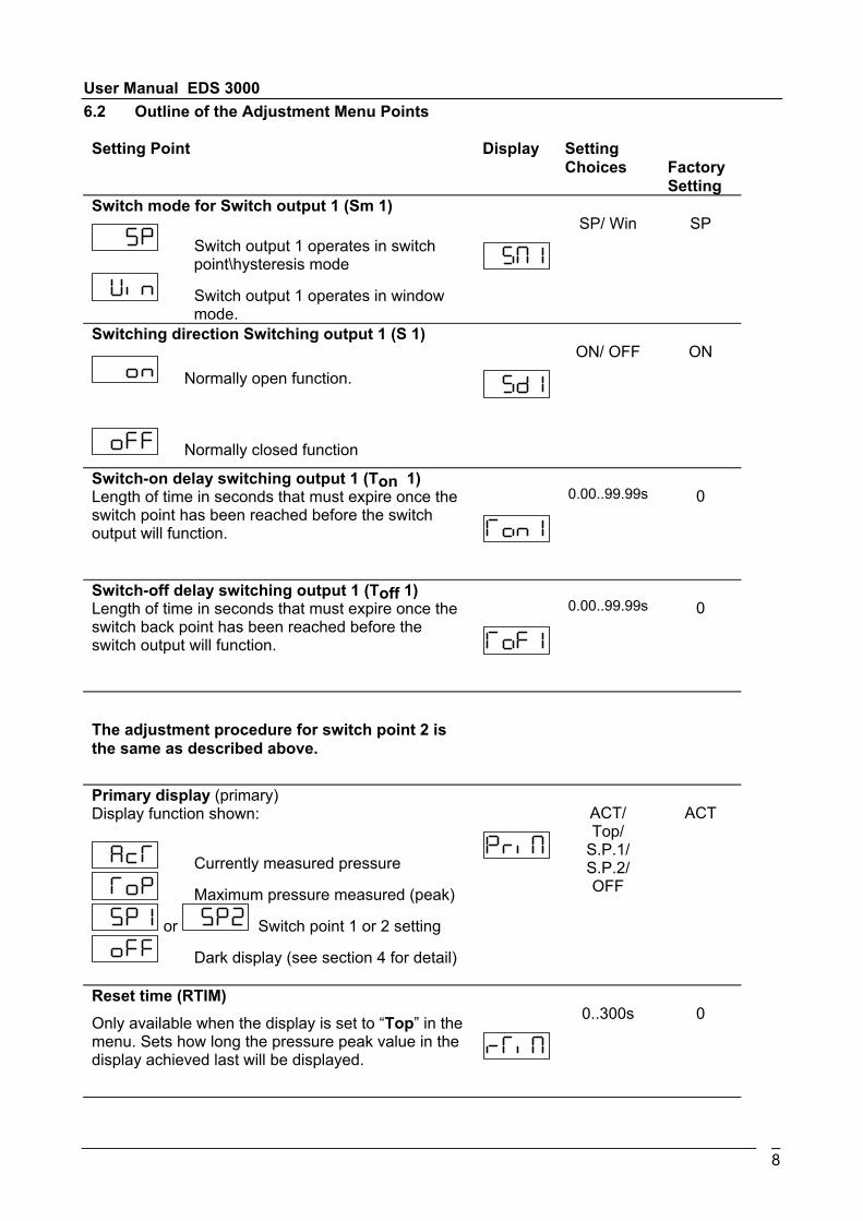
SettingSwitch mode for Switch output 1 (Sm 1)
Switch output 1 operates in switch point\hysteresis mode
Switch output 1 operates in window mode.
SP/ Win SP
Switching direction Switching output 1 (S 1)
Normally open function.
Normally closed function
ON/ OFF ON
Switch-on delay switching output 1 (Ton 1)Length of time in seconds that must expire once theswitch point has been reached before the switchoutput will function.
0.00..99.99s 0
Switch-off delay switching output 1 (Toff 1)Length of time in seconds that must expire once theswitch back point has been reached before theswitch output will function.
0.00..99.99s 0
The adjustment procedure for switch point 2 isthe same as described above.
Primary display (primary)Display function shown:
Currently measured pressure
Maximum pressure measured (peak)
or Switch point 1 or 2 setting
Dark display (see section 4 for detail)
ACT/Top/
S.P.1/S.P.2/OFF
ACT
Reset time (RTIM)Only available when the display is set to “Top” in themenu. Sets how long the pressure peak value in thedisplay achieved last will be displayed.
0..300s 0

User Manual EDS 3000
9
Adjustment Display Range ofadjustment
Default
Display
Display reacts slowly to pressure changes.
Display reacts normal to pressure changes.
Display reacts quickly to pressure changes.
SLOW/MEDI/FAST
MEDI
Pressure Range Scale
Pressure in Bar.
Pressure in PSI.
Pressure in MPa
The normal range can be scaledfreely. If this adjustment is selected, the decimalplace as well as upper and lower range limits mustbe adjusted. Example: If the range has been changed to0...215.5, the display value 215.5 corresponds to themaximum pressure capable of being measured bythe EDS.Application: Display other scales like KN, Kg, etc.
BAR/ PSI/ MPa/FREE
BAR
Decimal Place Only available when range is set to “FREE”. Placement of decimal point is selectable below adisplay value of 3000.
0..0.000 0.0
Low Range Only available when range is set to “FREE”. -999..9899
0.0
High Range Only available when range is set to “FREE”. -899..9899 Meas.
rangefinalvalue

User Manual EDS 3000
10
Analog Output
The analog output supplies a 4...20mA DC sourcing output signal.
The analog output supplies a 0...10VDC sourcing output signal.
MAMP/VOLT
VOLT
Zero Point Calibration (Calibrate)
The pressure at that point in time is stored as a new zero point. This ispossible in the area +/- 3% of thepressure range of the EDS.
This will be displayed if your new
calibration is within 3% of 0 bar
pressure.
This will appear if the pressure applied to the EDS is more than 3% of
the measuring range and a zero point
calibration is attempted.Example:If you have a 600 bar EDS, up to 18 bar can beapplied to the switch and a zero point calibrationcould be performed to have the display show 0 bar.
YES/ NO NO
VersionDisplays the current software version.
End
Use to exit the adjustment menu.
Continue adjustments.
YES/ NO NO
If menu adjustments were changed then upon exiting “ProG” will be displayed. This notifies theuser changes have been made and stored.
User Manual EDS 3000
11
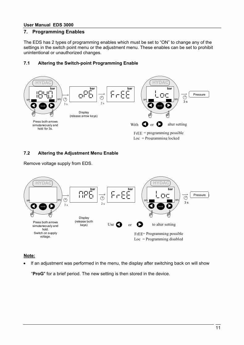
7. Programming Enables
The EDS has 2 types of programming enables which must be set to “ON” to change any of thesettings in the switch point menu or the adjustment menu. These enables can be set to prohibitunintentional or unauthorized changes. 7.1 Altering the Switch-point Programming Enable
3 s
Druckanzeige
3 s
With alter setting
Loc FrEE
= Programming locked
= programming possible
2 s SP1 SP2
HYDAC
mode
bar
SP1 SP2
HYDAC
mode
bar bar bar
or Press both arrows simutaneously and
hold for 3s.
Display (release arrow keys)
Pressure
7.2 Altering the Adjustment Menu Enable
Remove voltage supply from EDS.
3 s
Druckanzeige
3 s
Use to alter setting
Loc FrEE
= Programming disabled
= Programming possible
2 s SP1 SP2
HYDAC
mode
SP1 SP2
HYDAC
mode
bar bar bar
or Press both arrows simutaneously and
hold. Switch on supply
voltage.
Display (release both
keys)
Pressure
Note:• If an adjustment was performed in the menu, the display after switching back on will show
“ProG" for a brief period. The new setting is then stored in the device.

User Manual EDS 3000
12
8. Error Codes
If the EDS detects an error, then a corresponding error code will be displayed. Possible errorcodes are as follow:
E.01 The switching point and hysteresis have been set in such a way that the resulting switch-back point is no longer within the permissible setting range.
Corrective action: Correct the settings.
E.10 A data error has been detected in the saved settings. Possible causes are strong electromagnetic interference or an internal circuit fault.
Corrective action: Check the settings (programming enables, switch point settings, adjustment menu settings) and correct these if possible. If the errors occur frequently, please contact Hydac.
E.12 An error has been detected in the stored calibration data. Possible causes are strong electromagnetic interference or an internal circuit fault.
Corrective action: Switch the unit off and then on. If the error message is still displayed, the unit must be returned to the manufacture for re-calibration or repair.
E.20 A short circuit has been detected on a switch output.
Corrective action: Eliminate the short circuit.

User Manual EDS 3000
13
9. Technical Data
Inputs:Measuring Range – Ceramic - Absolute: 15, 50 psiOverload pressure: 2xBurst pressure: 3xMeasuring Range – Ceramic - Gauge: 0…15, 30, 50, 150, 250, 500 & -14…75 psiOverload pressure: 2xBurst pressure: 3xMeasuring Range – Thin Film DMS – Gauge: 0…1000, 3000, 6000, 9000 psiOverload pressure: 2xBurst pressure: 3xAccuracy data:Accuracy (display, analogue output): ≤ ±0.5 % FS typ.Repeatability ≤ ±0.25 % FS max.Temperature Drift: ≤ ±0.017%FS/°F max. zero point
≤ ±0.017%FS/°F max. spanAnalog signal output: Selectable 0 ...10VDC or 4 ... 20 mA DCSwitching outputs:Type: PNP-Transistor outputSwitching current: Max. 1.2 ACycles: > 100 MillionReaction time: < 10 msDESINA Diagnostic signal (Pin 2):Function I/O: HIGH-Level, I/O NOT: Low-levelLevel HIGH = +Supply VDC
LOW = <+0.3 VDC Switch on time (power on)ReactionEnvironment conditions:Normal temperature: -25.. + 80 °C (-13 ...+176°F)Ambient temperature: -25.. + 80 °C (-13 ...+176°F)Storage temperature: -40.. + 80 °C (-40 ...+176°F)Nominal temperature: -25.. + 85 °C (-13 ...+185°F)
-Mark: EN 50081-1, EN 50081-2,EN 50082-1, EN 61000-6-2
Vibration Resistance: 10 g / 0..500 HzShock Resistance: 50 g / 1msOther Data:Supply voltage: 18.. 32 VDCElectrical connection: M12x1 (4-pin or 5-pin)Power input: 100 mA (without switching output load)Enclosure rating: IP 67 (w/ molded M12 cable connector)Mechanical Connection: ¼ NPT male or SAE-6 male (standard)Parts in contact with medium: Stainless steel, Viton seal; CeramicHousing Material:Display: 4-digit, 7 segment LED, redWeight: approx. 300 g
Note: FS (Full Scale) = related to the full measuring range
User Manual EDS 3000
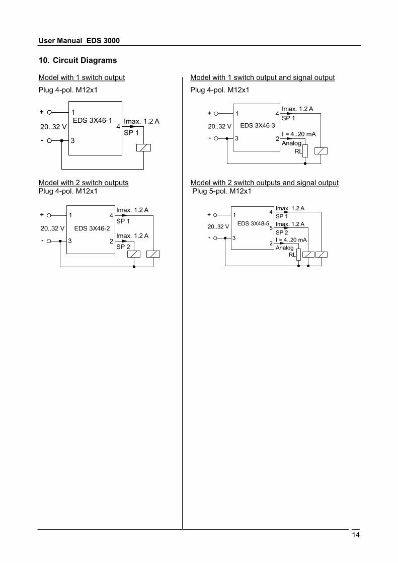
10. Circuit Diagrams
Model with 1 switch output Model with 1 switch output and signal outputPlug 4-pol. M12x1 Plug 4-pol. M12x1
MP
+
14
odel with 2 switch outputs Model with 2 switch outputs and signal outputlug 4-pol. M12x1 Plug 5-pol. M12x1
20..32 VImax. 1.2 AEDS 3X46-1
1
3
4
-SP 1
+
-
20..32 V
Imax. 1.2 A
EDS 3X46-3
1
3
4SP 1
RL
2I = 4..20 mAAnalog
Imax. 1.2 A
EDS 3X46-2
1
3
4+
-
20..32 V
2Imax. 1.2 A
SP 1
SP 2
Imax. 1.2 A
Imax. 1.2 ASP 1
SP 2EDS 3X48-5
1
3
4+
-
20..32 V 5
2 I = 4..20 mAAnalog
RL

User Manual EDS 3000
15
11. Model Code
Series #
Mechanical Connection 6 = 1/4”-18 NPT male thread (brass types 1 and 3)
Electrical Connection 6 = Plug M12x1, 4-pol.
8 = Plug M12x1, 5-pol.
(without quick coupling socket)
Output 1 = 1 Switching Output
2 = 2 Switch Output
3 = 1 Switch with analog output
Pressure Ranges in bar 1; 2.5 bar
Modification number 000 = Standard
(without quick coupling socket) only with the output version 1, 2 and 3
only with the output version 5
(only with electrical connection 6)
(only with electrical connection 6)
(only with electrical connection 6)
EDS 3 X 4 X - X - XXXX - XXX
Sensor Type 2 = Ceramic absolute
5 = 2 Switch with analog ouput (only with electrical connection 8)
3 = Ceramic Relative 4 = Thin-film relative
Type 2 (Ceramic - Absolute)
40; 60; 100; 250; 400; 600 bar 1; 2.5; 4; 10; 16; 25; 40 bar Type 3 (Ceramic relative)
Type 4 (Thin-film, relative) 150; 1000; 3000; 6000; 9000 bar
7 = SAE-6 male thread (9/16-18 UNF2A stainless steel type 4)
User Manual EDS 3000
16
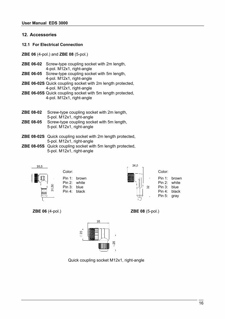
12. Accessories
12.1 For Electrical Connection
ZBE 06 (4-pol.) and ZBE 08 (5-pol.)
ZBE 06-02 Screw-type coupling socket with 2m length,4-pol. M12x1, right-angle
ZBE 06-05 Screw-type coupling socket with 5m length,4-pol. M12x1, right-angle
ZBE 06-02S Quick coupling socket with 2m length protected,4-pol. M12x1, right-angle
ZBE 06-05S Quick coupling socket with 5m length protected,4-pol. M12x1, right-angle
ZBE 08-02 Screw-type coupling socket with 2m length,5-pol. M12x1, right-angle
ZBE 08-05 Screw-type coupling socket with 5m length,5-pol. M12x1, right-angle
ZBE 08-02S Quick coupling socket with 2m length protected,5-pol. M12x1, right-angle
ZBE 08-05S Quick coupling socket with 5m length protected,5-pol. M12x1, right-angle
Color:
Pin 1: brownPin 2: whitePin 3: bluePin 4: blackPin 5: gray
Color:
Pin 1: brownPin 2: whitePin 3: bluePin 4: black
Quick coupling socket M12x1, right-angle
ZBE 06 (4-pol.) ZBE 08 (5-pol.)

User Manual EDS 3000
17
13. Dimensions