Electronic Preset Delivery System Smith Meter...
94
Bulletin MN06148 ║ Issue/Rev 0.5 (11/15) Electronic Preset Delivery System Smith Meter ® microLoad.net ™ Operator Reference Manual
Transcript of Electronic Preset Delivery System Smith Meter...
Bulletin MN06148 Issue/Rev 0.5 (11/15)
Electronic Preset Delivery System
Smith Meter®
microLoad.net™
Operator Reference Manual

Caution
The default or operating values used in this manual and in the program of the Smith Meter® microLoad.net™ are for factory testing only and should not be construed as default or operating values for your metering system. Each metering system is unique and each program parameter must be reviewed and programmed for that specific metering system application.
Disclaimer
FMC Technologies Measurement Solutions Inc hereby disclaims any and all responsibility for damages, including but not limited to consequential damages, arising out of or related to the inputting of incorrect or improper program or default values entered in connection with the microLoad.net.
Proprietary Notice
This document contains information that is proprietary to FMC Technologies Measurement Solutions Inc and is available solely for customer information. The information herein shall not be duplicated, used, or disclosed without prior permission of FMC Technologies Measurement Solutions Inc.FMC Technologies Measurement Solutions Inc will not be held responsible for loss of liquid or for damage of any kind or from any cause to the person or property of others, or for loss or profit, or loss of use, or any other special, incidental, or consequential damages caused by the use or misapplication of the contents stated herein.
Table of Contents
Section I – Introduction .................................................................................................................................................................1 Product Description..................................................................................................................................................................1 How To Use This Manual .........................................................................................................................................................1 Getting Started .........................................................................................................................................................................4Section II – Configuration Directories ...........................................................................................................................................5 Pulse Output Subdirectory .......................................................................................................................................................5
Configuration 101 – Pulse Output Enable .........................................................................................................................5 Configuration 102 – Pulse Output Pulses/Amount ............................................................................................................5 Configuration 103 – Pulse Output Units ............................................................................................................................5 Configuration 104 – Pulse Output Maximum Frequency ...................................................................................................6Digital Input Subdirectory ........................................................................................................................................................7 Configuration 201, 202, and 203 – Digital Input Functions ................................................................................................7Digtal Output Subdirectory ......................................................................................................................................................8 Configuration 301, 302, 303, 304, 305, and 306 – Digital Output Functions .....................................................................8Analog Input Subdirectory .......................................................................................................................................................9 Configuration 401 – Analog Input #1 Function ..................................................................................................................9 Configuration 402 – RTD Offset ........................................................................................................................................9 Configuration 411 – Analog Input #2 Function ..................................................................................................................9 Configuration 412 – Analog Input #2 Low Value ..............................................................................................................10 Configuration 413 – Analog Input #2 High Value .............................................................................................................10
Section III – General Purpose Directories ..................................................................................................................................11Date and Time Subdirectory ..................................................................................................................................................11 General Purpose 101 – Date ...........................................................................................................................................11 General Purpose 102 – Time ..........................................................................................................................................12Units Subdirectory .................................................................................................................................................................12 General Purpose 111 – Flow Rate Time .........................................................................................................................12 General Purpose 112 – Flow Rate Descriptor .................................................................................................................13 General Purpose 113 – Volume Units .............................................................................................................................13 General Purpose 114 – Volume Descriptor .....................................................................................................................13 General Purpose 115 – Mass Units ................................................................................................................................14 General Purpose 116 – Mass Descriptor ........................................................................................................................14Display Subdirectory ..............................................................................................................................................................14 General Purpose 121 – Position ID .................................................................................................................................15 General Purpose 122 – Ready Message ........................................................................................................................16 General Purpose 123 – Delivery (Run) Screen ...............................................................................................................16 General Purpose 124 – Display Resolution .....................................................................................................................16 General Purpose 125 – Decimal/Comma ........................................................................................................................16 General Purpose 126 – Default/Translated Literals .........................................................................................................16Timeouts Subdirectory ...........................................................................................................................................................17 General Purpose 131 – Dynamic Display Timeout ..........................................................................................................17 General Purpose 132 – Auto Reset Timer .......................................................................................................................17 General Purpose 133 – Internal Total Start Hour ............................................................................................................17Control Subdirectory ..............................................................................................................................................................17 General Purpose 141 – Number of Batches/Transaction ................................................................................................18 General Purpose 142 – Recipes per Transaction ............................................................................................................18 General Purpose 143 – Start Key Disabled .....................................................................................................................18 General Purpose 144 – Transaction Termination .............................................................................................................18 General Purpose 145 – Auto Start ..................................................................................................................................18Permissive Subdirectory ........................................................................................................................................................19 General Purpose 151 – Permissive #1 Sense .................................................................................................................19 General Purpose 152 – Permissive #1 Message ............................................................................................................19

Table of Contents
General Purpose 153 – Permissive #1 Restart ...............................................................................................................19 General Purpose 154 – Permissive #2 Sense .................................................................................................................20 General Purpose 155 – Permissive #2 Message ............................................................................................................20 General Purpose 156 – Permissive #2 Restart ...............................................................................................................20Security Subdirectory .............................................................................................................................................................21 General Purpose 161 – Level 1 Access Code .................................................................................................................21 General Purpose 162 – Level 2 Access Code .................................................................................................................21 General Purpose 163 – Level 3 Access Code .................................................................................................................22 General Purpose 164 – Security Input Access Level ......................................................................................................22 General Purpose 165 – Diagnostics Security Level ........................................................................................................22 General Purpose 166 – Set Parameter Security Level ....................................................................................................22
Section IV – Flow Control ...........................................................................................................................................................23Valve Type Subdirectory .........................................................................................................................................................23 Flow Control 201 – Valve Type .........................................................................................................................................23 Flow Profile Subdirectory .......................................................................................................................................................23 Flow Control 202 – Low Flow Start Rate .........................................................................................................................23 Flow Control 203 – Low Flow Start Amount ....................................................................................................................23 Flow Control 204 – Low Flow Start Percentage ..............................................................................................................24 Flow Control 205 – Low Flow Start Condition .................................................................................................................24 Flow Control 206 – Minimum Flow Rate ..........................................................................................................................24 Flow Control 207 – High Flow Rate .................................................................................................................................24 Flow Control 208 – Second High Flow Rate ....................................................................................................................24 Flow Control 209 – Flow Tolerance Percentage ..............................................................................................................24 Flow Control 210 – Flow Tolerance Rate .........................................................................................................................24 Flow Control 211 – First Trip Amount ..............................................................................................................................25 Flow Control 212 – Second Trip Amount .........................................................................................................................25 Flow Control 213 – Second Trip Auto Adjust ...................................................................................................................25 Flow Control 221 – Excess High Flow Rate ....................................................................................................................25 Flow Control 222 – Low Flow Rate Alarm Limit ...............................................................................................................25 Flow Control 223 – Overrun Alarm Limit .........................................................................................................................25Delays/Timers Subdirectory ...................................................................................................................................................26 Flow Control 231 – Valve Delay To Open ........................................................................................................................26 Flow Control 232 – Start After Stop Delay .......................................................................................................................26 Flow Control 233 – Pump Delay To Off ............................................................................................................................26 Flow Control 234 – Zero Flow Timer ...............................................................................................................................26 Flow Control 235 – Valve Fault Timeout ..........................................................................................................................26LACT Features Subdirectory ..................................................................................................................................................26 System Flow Control Directory 241 – Sample Rate ........................................................................................................26 System Flow Control Directory 242 – Sampler Minimum Pulse ......................................................................................27 System Flow Control Directory 243 – BS&W Maintenance Value ...................................................................................27 System Flow Control Directory 244 – Divert Percentage ................................................................................................27 System Flow Control Directory 245 – BS&W Time Before Divert ....................................................................................27 System Flow Control Directory 246 – Minimum Divert Time ...........................................................................................27 System Flow Control Directory 247 – Divert Time at Start ..............................................................................................27 System Flow Control Directory 248 – Divert Cycle Count Alarm Limit ............................................................................27 System Flow Control Directory 249 – Sale Pump Delay to On ...........................................................................................
Section V – Volume Accuracy .....................................................................................................................................................28Pulse Input Subdirectory ........................................................................................................................................................28 Volume Accuracy 301 – K Factor ....................................................................................................................................28 Volume Accuracy 302 – Pulse In Type.............................................................................................................................28 Volume Accuracy 303 – Pulse Input Channel .................................................................................................................28 Volume Accuracy 304 – Dual Pulse Error Count .............................................................................................................29

Table of Contents
Volume Accuracy 305 – Dual Pulse Error Reset .............................................................................................................29 Volume Accuracy 306 – Dual Pulse Flow Rate Cutoff .....................................................................................................29 Volume Accuracy 307 – Pulse Security Alarm Amount ...................................................................................................29 Volume Accuracy 308 – Pulse Period Sample Count ......................................................................................................29 Volume Accuracy 309 – Pulse Multiplier..........................................................................................................................29Preset Subdirectory ................................................................................................................................................................30 Volume Accuracy 321 – Preset Amount Type ..................................................................................................................30 Volume Accuracy 322 – Delivery Amount Type ...............................................................................................................30 Volume Accuracy 323 – Maximum Preset .......................................................................................................................30 Volume Accuracy 324 – Minimum Preset ........................................................................................................................30 Volume Accuracy 325 – Auto Preset ...............................................................................................................................31 Volume Accuracy 326 – Auto Preset Increment ..............................................................................................................31Prove Control Subdirectory ....................................................................................................................................................32 Volume Accuracy 331 – Auto Prove Select .....................................................................................................................32 Volume Accuracy 332 – Proving Counters ......................................................................................................................32Meter Factors Subdirectory ....................................................................................................................................................33 Volume Accuracy 341 – Meter Factor 1 ...........................................................................................................................33 Volume Accuracy 342 – Flow Rate 1 ...............................................................................................................................33 Volume Accuracy 343 – Meter Factor 2 ...........................................................................................................................33 Volume Accuracy 344 – Flow Rate 2 ...............................................................................................................................33 Volume Accuracy 345 – Meter Factor 3 ...........................................................................................................................33 Volume Accuracy 346 – Flow Rate 3 ...............................................................................................................................33 Volume Accuracy 347 – Meter Factor 4 ...........................................................................................................................33 Volume Accuracy 348 – Flow Rate 4 ...............................................................................................................................33 Volume Accuracy 349 – Master Meter Factor ..................................................................................................................34 Volume Accuracy 350 – Linearized Factor Deviation ......................................................................................................34 Volume Accuracy 351 – Meter Factor Variation Select ....................................................................................................34 Volume Accuracy 352 – Meter Factor Percent Change Per Degree Temperature ...........................................................34 Volume Accuracy 353 – Meter Factor Variation Reference Temperature ........................................................................34Mass Meter Subdirectory .......................................................................................................................................................35 Volume Accuracy 361 – Mass Meter Type .......................................................................................................................35 Volume Accuracy 362 – Mass Meter Sequence Number ................................................................................................35 Volume Accuracy 363 – S-Mass Coefficient Ka ..............................................................................................................35 Volume Accuracy 364 – S-Mass Coefficient Kb ..............................................................................................................35 Volume Accuracy 365 – S-Mass Coefficient Kc...............................................................................................................36 Volume Accuracy 366 – S-Mass Density Factor ..............................................................................................................36 Volume Accuracy 367 – Mass Meter Pulse Multiplier ......................................................................................................36 Volume Accuracy 368 – Mass Meter Low Flow Cutoff ....................................................................................................36 Volume Accuracy 369 – Mass Meter Tube Material .........................................................................................................37 Volume Accuracy 370 – Mass Meter Model ....................................................................................................................37
Section VI – Temperature/Density Directories ............................................................................................................................38 Temperature/Density 401 – Temperature Units ...............................................................................................................38 Temperature/Density 402 – Reference Temperature .......................................................................................................38 Temperature/Density 403 – Maintenance Temperature ...................................................................................................38 Temperature/Density 404 – High Temperature Alarm Limit .............................................................................................38 Temperature/Density 405 – Low Temperature Alarm Limit ..............................................................................................39Density Subdirectory ..............................................................................................................................................................39 Temperature/Density 411 – Density Units .......................................................................................................................39 Temperature/Density 412 – API Table .............................................................................................................................39 Temperature/Density 413 – Reference Density ...............................................................................................................40

Table of Contents
Temperature/Density 414 – High Density Alarm Limit .....................................................................................................41 Temperature/Density 415 – Low Density Alarm Limit ......................................................................................................41 Temperature/Density 416 – % Weight H2O .....................................................................................................................41 Temperature/Density 417 – Reference Density's Temperature........................................................................................41 Temperature/Density 418-420 – Ethanol Coefficients .....................................................................................................41 Temperature/Density 421 – Aromatic Hydrocarbon Product ...........................................................................................42 Temperature/Density 422 – Aromatic Hydrocarbon Reference Density ..........................................................................42 Temperature/Density 423 – Reference Density for C Tables ...........................................................................................42Section VII – Pressure Directories .........................................................................................................................................43General Purpose ....................................................................................................................................................................43 Pressure 501 – Pressure Units ........................................................................................................................................42 Pressure 502 – Maintenance Pressure ...........................................................................................................................42 Pressure 503 – Pressure Coefficient ...............................................................................................................................42 Pressure 504 – High Pressure Alarm Limit .....................................................................................................................43 Pressure 505 – Low Pressure Alarm Limit ......................................................................................................................44 Pressure 506 – Ambient Pressure ...................................................................................................................................44 Pressure 511 – Minimum Back Pressure Flow Rate Timer .............................................................................................44 Pressure 512 – Back Pressure Percent Reduction .........................................................................................................44 Pressure 513 – Minimum Back Pressure Flow Rate .......................................................................................................44 Pressure 514 – Back Pressure Flow Recovery Timer .....................................................................................................45 Pressure 515 – Differential Pressure ...............................................................................................................................45 Pressure 516 – Flow Recovery Pressure ........................................................................................................................45 Pressure 521 – Vapor Pressure Calculation Method .......................................................................................................45 Pressure 522 – Vapor Pressure 1 ....................................................................................................................................46 Pressure 523 – Vapor Pressure Temperature 1 ...............................................................................................................46 Pressure 524 – Vapor Pressure 2 ....................................................................................................................................46 Pressure 525 – Vapor Pressure Temperature 2 ...............................................................................................................46 Pressure 526 – Vapor Pressure 3 ....................................................................................................................................46 Pressure 527 – Vapor Pressure Temperature 3 ...............................................................................................................46
Section VIII – Alarm Directories ..................................................................................................................................................47 Alarm 601 – Driver Clearable Alarms ..............................................................................................................................47 Alarm 602 – Powerfail Alarm ...........................................................................................................................................47Configure Alarm Directory ......................................................................................................................................................47 Alarm 611 to 675 – Alarm Configuration .........................................................................................................................47 Alarm 681 to 685 – User Alarms Subdirectory ................................................................................................................51 Alarm 691 to 695 – User Alarm Messages ......................................................................................................................51
Section IX – Communications Directories ..................................................................................................................................52 Communications 701 – Comm Port 1 Function ...............................................................................................................52 Communications 702 – Comm Port 1 Baud Rate ............................................................................................................54 Communications 703 – Comm Port 1 Data/Parity ...........................................................................................................54 Communications 704 – Comm Port 1 Control .................................................................................................................55 Communications 705 – Comm Port 1 Timeout ................................................................................................................55 Communications 706 – Comm Port 1 Mode ....................................................................................................................55 Communications 707 – Comm Port 2 Function ...............................................................................................................52 Communications 708 – Comm Port 2 Baud Rate ............................................................................................................54 Communications 709 – Comm Port 2 Data/Parity ...........................................................................................................54 Communications 710 – Comm Port 2 Control .................................................................................................................55 Communications 711 – Comm Port 2 Timeout ................................................................................................................55 Communications 712 – Comm Port 2 Mode ....................................................................................................................55 Communications 713 – Comm Port 3 Function ...............................................................................................................52

Communications 714 – Comm Port 3 Baud Rate ............................................................................................................54 Communications 715 – Comm Port 3 Data/Parity ...........................................................................................................54 Communications 716 – Comm Port 3 Control .................................................................................................................55 Communications 717 – Comm Port 3 Timeout ................................................................................................................55 Communications 718 – Comm Port 3 Mode ....................................................................................................................55Host Interface Subdirectory ....................................................................................................................................................56 Communications 721 – IP Address/Serial Port Address .................................................................................................57 Communications 722 – Netmask Address (Subnet Mask) ..............................................................................................57 Communications 723 – Gateway Address .......................................................................................................................57 Communications 724 – Ethernet Control.........................................................................................................................57 Communications 725 – Comm Link Programming ..........................................................................................................57 Communications 726 – Ethernet Host Timeout ...............................................................................................................58 Communications 727 – Modbus Endian Select ...............................................................................................................58 Communications 728 – Printer IP Address ......................................................................................................................58Reports Subdirectory .............................................................................................................................................................58 Communications 731 – Report Selection ........................................................................................................................58 Communications 732 – Report Volume Resolution .........................................................................................................59 Communications 733, 734, 735, and 736 – Report HM Classification 1, 2, 3, 4 .............................................................59 Communications 737 – Summary Report Print Time ......................................................................................................59 Communications 738 – Summary Report Interval ...........................................................................................................60 Communications 739 – User Text Archived .....................................................................................................................60 Communications 740 – Summary Report Interval ...........................................................................................................60 Communications 741 – Auto Reprint ...............................................................................................................................60 Smith Meter Card Reader Subdirectory .................................................................................................................................61 Communications 751 – Card Validation ...........................................................................................................................61 Communications 752 – Card Data Valid Timeout ............................................................................................................61Prompts Subdirectory .............................................................................................................................................................61Communications 761 – Prompts Used ...................................................................................................................................62Communications 762 – Prompt Timeout ................................................................................................................................62Communications 763 – Prompt Validation ..............................................................................................................................62Communications 764 – Prompt #1 Message ........................................................................................................................63Communications 765 – Prompt Input #1 Type ........................................................................................................................63Communications 766 – Prompt #1 Length .............................................................................................................................63 Communications 767 – Prompt #2 Message ...................................................................................................................63 Communications 768 – Prompt Input #2 Type .................................................................................................................63 Communications 769 – Prompt #2 Length ......................................................................................................................63 Communications 770 – Prompt #2 Message ...................................................................................................................63 Communications 771 – Prompt Input #3 Type .................................................................................................................63 Communications 772 – Prompt #3 Length ......................................................................................................................63 Communications 773 – Prompt #4 Message ...................................................................................................................63 Communications 774 – Prompt Input #4 Type .................................................................................................................63 Communications 775 – Prompt #4 Length ......................................................................................................................63 Communications 776 – Prompt #5 Message ...................................................................................................................63 Communications 777 – Prompt Input #5 Type .................................................................................................................63 Communications 778 – Prompt #5 Length ......................................................................................................................63
Section X – Additive Directories .................................................................................................................................................64 Additive 801 – Injector #1 Type ........................................................................................................................................64 Additive 802 – Injector #2 Type ........................................................................................................................................64 Additive 803 – Injector #3 Type ........................................................................................................................................64 Additive 804 – Injector #4 Type ........................................................................................................................................64Additive Units Subdirectory ....................................................................................................................................................65
Table of Contents

Additive 811 – Additive Pacing Units ...............................................................................................................................65 Additive 812 – Additive Injection Units Descriptor ...........................................................................................................65 Additive 813 – Additive Totals Units Descriptor ...............................................................................................................66 Additive 814 – Injection/Totalization Conversion Factor ..................................................................................................66 Injector Control Subdirectory .................................................................................................................................................67 Additive 821 – Additive Stop Option ................................................................................................................................67 Additive 822 – Additive Stop Volume ...............................................................................................................................67 Additive 823 – Additive Clean Line Alarm .......................................................................................................................67 Additive 824 – Piston Injector Feedback Errors ...............................................................................................................67 Additive 825 – Piston Stop Action ...................................................................................................................................67Metered Injector Subdirectory ................................................................................................................................................68 Additive 831 – Metered Injector K Factor ........................................................................................................................68 Additive 832 – Metered Injector Meter Factor ..................................................................................................................68 Additive 833 – Metered Injector High Tolerance ..............................................................................................................68 Additive 834 – Metered Injector Low Tolerance ...............................................................................................................68 Additive 835 – Metered Injector Maximum Tolerance Error .............................................................................................68 Smart Injector Subdirectory....................................................................................................................................................69 Additive 841 – Smart Injector #1 Address .......................................................................................................................69 Additive 842 – Smart Injector #2 Address .......................................................................................................................69 Additive 843 – Smart Injector #3 Address .......................................................................................................................69 Additive 844 – Smart Injector #4 Address .......................................................................................................................69
Section XI – Recipe Directories ..................................................................................................................................................70 Recipe Setup Subdirectory ....................................................................................................................................................71 Recipe rr01 – Recipe Used .............................................................................................................................................71 Recipe rr02 – Recipe Name ............................................................................................................................................71 Recipe Injectors Subdirectory ................................................................................................................................................71 Recipe rr11, rr13, rr15, and rr17 – Injector Volume .........................................................................................................71 Recipe rr12, rr14, rr16, and rr18 – Injector Rate .............................................................................................................72
Section XII – Diagnostic Directories ...........................................................................................................................................73 Program Mode Diagnostics ....................................................................................................................................................73Section XIII – Appendix ..............................................................................................................................................................83 Appendix – Alarms .................................................................................................................................................................83 Metered Injector Alarms .........................................................................................................................................................84 OR: Overspeed Metered Injector ............................................................................................................................................84 NA: No Additive Pulses Alarm ................................................................................................................................................84 RA: Additive Frequency Alarm................................................................................................................................................84 KA: Low Additive Volume ........................................................................................................................................................84Section XIV – Related Publications ............................................................................................................................................85
Table of Contents

Issue/Rev. 0.5 (11/15) MN06148 • Page 1
Section I – Introduction
Product Description
The Smith Meter® microLoad.net™ is a micro-processor based single arm, single product electronic preset instrument that supports up to 12 recipes. It is configurable to support a variety of user applications. Optimum measurement accuracy is attained through continuous linearization of the meter factor with changes in flow rates. The microLoad.net is also capable of maintaining back pressure on the measurement system using automatic flow optimization. Volumetric correction is calculated directly from published API equations providing precise volumetric measurement results. Precise temperature, pressure compensation (using programmed maintenance pressure), and density correction are options that are available in the instrument.The dynamic real-time display of the current actual operating conditions of the system provides the operator with valuable system information while the system is operating. The microLoad.net provides several loading system control functions: additive injection, pump control, alarm control, set stop, valve control, back pressure control, automatic adjustment of final trip point, and flow rate controlled injector. Other significant features are as follows:
• 200 Driver Database • Ethernet Connectivity • Three Multi-drop Serial Communications Ports • Event Logging / Audit Trail • User Configurable I/O • Three Security Levels • Optional Battery Backed Display per OIML • Programmable Language/Messages • Automated Proving • API Tables from LPG to Crude Oil
How To Use This Manual
This manual is to be used as a reference guide to the program codes available in the microLoad.net. The directories and subdirectories which contain the program codes are listed above each set of parameters.The program code explanations frequently list “fatal” or “critical” warnings, or indicate that in some circumstances, the code is “no entry.” A fatal warning is triggered by a selection that the microLoad.net cannot accept and will not allow to be entered. Possible causes include an entry that falls outside an allowable range, or an entry that seriously conflicts with a previous entry. A critical warning signals that a selection is incompatible with a previously configured program code. The microLoad.net will accept the new entry, but the selection will undoubtedly cause a problem in operation and should be changed. “No entry” indicates that a program code is unavailable and will not appear on the menu, because previous selections make it irrelevant. For example, pulse output codes will not appear unless pulse output has been enabled.

Page 2 • MN06148 Issue/Rev. 0.5 (11/15)
Section I – Introduction
The main system directories are as follows:
Configuration Directories 100 – Pulse Outputs 200 – Digital Inputs 300 – Digital Outputs 400 – Analog Inputs
General Purpose Directories 10X – Date and Time 11X – Units 12X – Display 13X – Timeouts 14X – Control 15X – Permissives 16X – Security
Flow Control Directories 20X – Valve Type 21X – Flow Profile 22X – Alarm Limits 23X – Delays/Timers
Volume Accuracy Directories 30X…31X – Pulse Input 32X – Preset 33X – Prove Control 34X…35X – Meter Factors 36X…370 – Mass Meter
Temperature/Density Directories 40X – Temperature 41X – Density
Pressure Directories 50X – General Purpose 51X – BackPressure 52X – Vapor Pressure
Alarm Directories 601 – Driver Clearable 602 – Powerfail Alarm 61X…66X – Configure Alarms 61X – System Alarms 62X – Flow Alarms 63X…64X – Temp/Density Pressure Alarms 65X – Meter Alarms 66X…67X – Injector Alarms 68X – User Alarms 69X – User Alarm Messages
Communications Directories 70X…71X – Comm Port Configuration 72X – Host Interface 73X – Reports 75X – Card Reader 76X…77X – Prompts

Issue/Rev. 0.5 (11/15) MN06148 • Page 3
Section I – Introduction
Additive Injector Directories 80X – Injector Type 81X – Additive Units 82X – Injector Control 83X – Metered Injector Menu 84X – Smart Injector Menu
Recipe Directories RR0X – General RR1X – Injector
Diagnostic Directories Analog Input Test Digital Input Test Digital Output Test Pulse Input Test Pulse Output test Prove Metered Injector Adds Communications Test Keypad Test Display Pixel Test Boolean Algebraic Reset Totals Reset Dual Pulse Erase Event Log Erase Transaction Log Erase Web Pages Card Reader DB Update Mass Meter Menu Upgrade Firmware Factory Initialize

Page 4 • MN06148 Issue/Rev. 0.5 (11/15)
Getting Started
The program codes may be reviewed or altered using both the keypad and display on the face of the microLoad.net or by using Micromate software through one of the communications ports. The following provides instructions on use of the keypad and display for program code operations. Before starting, refer to the Operations Manual, MN06149, Section II for microLoad.net keypad functions.
The Program Mode Menu is used for program code manipulation. From the “Ready” screen the user first goes to the “Main Menu” screen by depressing the ENTER key.
Select “Program Mode Menu” and depress the ENTER key. The microLoad.net will then request the passcode to allow entry into Program Mode Menu. The default passcode for a new microLoad.net is “0000”. After entering the proper passcode the Program Mode Menu screens will be accessible.
Section I – Introduction
Main Menu
Dynamic DisplaysPrint MenuProgram Mode MenuDiagnostics Menu
microLoad.net ReadyXXXXXXXX
Press SET key
MM/DD/YY H:MM:SS PM
Program Mode Menu
Alarm DirCommunications DirAdditive Inj DirRecipe DirDiagnostics
Enter Passcode>______
Program Mode Menu
Configuration DirGen Purpose DirFlow Control DirVol Accuracy DirTemp/Density DirPressure Dir

Issue/Rev. 0.5 (11/15) MN06148 • Page 5
Section II – Configuration Directories
There are four (4) Configuration Subdirectories in the microLoad.net.
Pulse Output Subdirectory
If Pulse Output is not enabled, parameters Configuration 102 thru 104 will not be available for entry.
Configuration 101 – Pulse Output EnableThis program code allows a pulse output to be activated for the microLoad.net. Selections are as follows: • No • Yes
Steps to ENABLE Pulse Outputs: • At first Pulse Output screen press ENTER • On “101 Out Enable” screen select “Yes” • Press ENTER • Pulse Output Directory opens for editing
Configuration 102 – Pulse Output Pulses/AmountThis five-digit parameter defines the pulse output resolution, the number of pulses per unit of volume to be generated (e.g., 0.1 will output 1 pulse for every 10 units of volume). The range of this parameter is 0.00 through 999.99.Note: No entry if Pulse Output Enable = No.Help: “Enter output pulses per unit of volume or mass.”
Configuration 103 – Pulse Output UnitsThis parameter defines the volume type used to pace the pulse output. Selections are as follows: • IV [Indicated Volume or Raw] • GV [Gross] • GST [Gross Standard Temperature] • GSV [Gross at Standard Temperature and Pressure] • MassCritical: Selected units not available.Note: No entry if Pulse Output Enable = No.Help: “Select volume type on which to be based on.”
Configuration Dir
Pulse OutputsDigital InputsDigital OutputsAnalog Inputs
Pulse Outputs
Out Enable YESPulses/Amt x.xxPulse Units xxxMax Freq xxxx
Pulse Outputs
Out Enable NO
101 Out Enable
No NOYes

Page 6 • MN06148 Issue/Rev. 0.5 (11/15)
Section II – Configuration Directories
Configuration 104 – Pulse Output Maximum FrequencyThis four-digit entry limits the pulse output frequency for Pulse Output #1 to a fixed range (0 to 3500 Hz) to avoid over-speeding the device attached to the pulse output. All of the intended pulses will eventually be transmitted; the total period will be increased if required to ensure the correct number of pulses is output. A 0 entry disables this feature.Fatal: Entry is out of specified range.Note: No entry if Pulse Output Enable = No.Help: “Enter frequency output should be limited to (0 to 3500 Hz).”

Issue/Rev. 0.5 (11/15) MN06148 • Page 7
Section II – Configuration Directories
Digital Input Subdirectory
The microLoad.net has provisions for three (3) digital (ON/OFF) inputs.
Configuration 201, 202, 203 – Digital Input FunctionsThese program codes define the function of each digital input. Except for general purpose inputs, duplicate assignments are not allowed. Must be at highest level of security to program or de-program security input. Injector I/O assignment must match Injector type and digital output assigned for the injector. All Digital Inputs are DC type. Selections are as follows:
• NA • Security Switch • Permissive #1 • Permissive #2 • First/Second High Flow Switch • Remote Start • Remote Stop • Transaction Reset • General Purpose Input • Printer Tray Switch • Piston Injector 1 Feedback • Piston Injector 2 Feedback • Piston Injector 3 Feedback • Piston Injector 4 Feedback • Recipe Select 1 • Recipe Select 2 • Recipe Select 3 • Low Flow Select
201 1 DC
NANASecurityPermissive 1Permissive 21st/2nd Hi FlowRemote StartRemote StopTransaction ResetGen Purpose InPrint Tray SwitchPiston Inj 1 FdbkPiston Inj 2 FdbkPiston Inj 3 FdbkPiston Inj 4 FdbkPRINT=Help more...
202 2 DC
NANASecurityPermissive 1Permissive 21st/2nd Hi FlowRemote StartRemote StopTransaction ResetGen Purpose InPrint Tray SwitchPiston Inj 1 FdbkPiston Inj 2 FdbkPiston Inj 3 FdbkPiston Inj 4 FdbkPRINT=Help more...
203 3 DC
NANASecurityPermissive 1Permissive 21st/2nd Hi FlowRemote StartRemote StopTransaction ResetGen Purpose InPrint Tray SwitchPiston Inj 1 FdbkPiston Inj 2 FdbkPiston Inj 3 FdbkPiston Inj 4 FdbkPRINT=Help more...
Digital Inputs
1 DC xxx2 DC xxx3 DC xxx

Page 8 • MN06148 Issue/Rev. 0.5 (11/15)
Section II – Configuration Directories
Digital Output Subdirectory
The microLoad.net has provisions for six (6) digital (ON/OFF) outputs. Digital Outputs 1 and 2 are DC type. Digital Outputs 3 through 6 are AC type.
Configuration 301-306 – Digital Output FunctionsThis program code defines the function of a digital output. If a valve is being configured, both upstream and downstream solenoids must be assigned. Except for general purpose outputs, duplicate assignments are not allowed. Metered Injector Solenoid is not available with Dual Channel. Selections are as follows: • NA • Pump • Upstream Solenoid • Downstream Solenoid • Alarm Relay #1 • Alarm Relay #2 • General Purpose Output • Stop Relay • Piston Injector 1-4 • Metered Injector Solenoid • Additive Pump #1 • Additive Pump #2 • Additive Pump #3 • Additive Pump #4 • Diverter • Sampler Pulse Out • Sampler Sel 1 • Sampler Sel 2 • Sampler Sel 3 • Sampler Sel 4 • Sale Pump
Critical: Output assignments must be unique [except for general purpose function].Critical: Metered injector pulse input not configured.Critical: Both upstream and downstream solenoids required.Critical: Injector I/O assignment does not match type.Critical (for Diverter, Sampler and Sale Pump options): Functions must be unique.Critical for Diverter: BS&W probe must be configured.
Digital Outputs
1 DC xxx2 DC xxx3 AC xxx4 AC xxx5 AC xxx6 AC xxx
Issue/Rev. 0.5 (11/15) MN06148 • Page 9
Section II – Configuration Directories
Analog Input Subdirectory
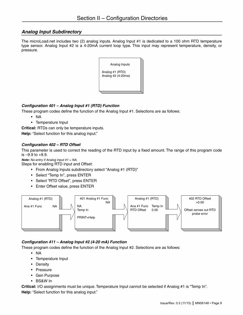
The microLoad.net includes two (2) analog inputs. Analog Input #1 is dedicated to a 100 ohm RTD temperature type sensor. Analog Input #2 is a 4-20mA current loop type. This input may represent temperature, density, or pressure.
Configuration 401 – Analog Input #1 (RTD) FunctionThese program codes define the function of the Analog Input #1. Selections are as follows: • NA • Temperature InputCritical: RTDs can only be temperature inputs.Help: “Select function for this analog input.”
Configuration 402 – RTD OffsetThis parameter is used to correct the reading of the RTD input by a fixed amount. The range of this program code is –9.9 to +9.9.Note: No-entry if Analog Input #1 = NA.Steps for enabling RTD input and Offset: • From Analog Inputs subdirectory select “Analog #1 (RTD)” • Select “Temp In”, press ENTER • Select “RTD Offset”, press ENTER • Enter Offset value, press ENTER
Configuration 411 – Analog Input #2 (4-20 mA) FunctionThese program codes define the function of the Analog Input #2. Selections are as follows: • NA • Temperature Input • Density • Pressure • Gen Purpose • BS&W InCritical: I/O assignments must be unique. Temperature Input cannot be selected if Analog #1 is “Temp In”.Help: “Select function for this analog input.”
Analog Inputs
Analog #1 (RTD)Analog #2 (4-20ma)
402 RTD Offset >0.00
Offset zeroes out RTD probe error
Analog #1 (RTD)
Ana #1 Func NA
401 Analog #1 FuncNA
NATemp In
PRINT=Help
Analog #1 (RTD)
Ana #1 Func Temp In RTD Offset 0.00
Page 10 • MN06148 Issue/Rev. 0.5 (11/15)
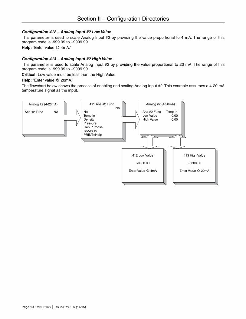
Configuration 412 – Analog Input #2 Low ValueThis parameter is used to scale Analog Input #2 by providing the value proportional to 4 mA. The range of this program code is -999.99 to +9999.99.Help: “Enter value @ 4mA.”
Configuration 413 – Analog Input #2 High ValueThis parameter is used to scale Analog Input #2 by providing the value proportional to 20 mA. The range of this program code is -999.99 to +9999.99.Critical: Low value must be less than the High Value.Help: “Enter value @ 20mA.”The flowchart below shows the process of enabling and scaling Analog Input #2. This example assumes a 4-20 mA temperature signal as the input.
Section II – Configuration Directories
Analog #2 (4-20mA)
Ana #2 Func Temp InLow Value 0.00High Value 0.00
Analog #2 (4-20mA)
Ana #2 Func NA
411 Ana #2 FuncNA
NATemp InDensityPressureGen PurposeBS&W InPRINT=Help
412 Low Value
>0000.00
Enter Value @ 4mA
413 High Value
>0000.00
Enter Value @ 20mA

Issue/Rev. 0.5 (11/15) MN06148 • Page 11
Section III – General Purpose Directories
There are seven (7) General Purpose subdirectories.
Date and Time Subdirectory
General Purpose 101 – DateThis entry allows the operator to set the date on the microLoad.net. When the month, day, and year have been entered, move to “Accept New Date” and press ENTER. The new date has been accepted. • Month • Day • Year • Accept New DateFatal: Invalid date.
Steps to changing microLoad.net Date: • Select “Month”, press ENTER • Enter value for month (1-12), press ENTER • Select “Day”, press ENTER • Enter value for day of the month (1-31), press ENTER • Select “Year”, press ENTER • Enter value for year (4 digit), press ENTER • Select “Accept New Date”, press ENTER
Gen Purpose Dir
Date and TimeUnitsDisplayTimeoutsControlPermissivesSecurity
Date and Time
101 Date xx/xx/xx102 Time xx:xx:xx
101 Date xx/xx/xx
Month xxDay xxYear xxxxAccept New Date

Page 12 • MN06148 Issue/Rev. 0.5 (11/15)
Section III – General Purpose Directories
General Purpose 102 – TimeA correction or change to the time can be made through this entry. The Time parameter allows for either an AM/PM format or the military (24 hour) format. To accept the new time, move the cursor to “Accept New Time” and press ENTER. The time has been accepted and the screen reverts to the Date and Time display. Selections are as follows: • Hours • Min • Time Type • Accept New TimeFatal: Invalid time.
Steps to changing microLoad.net Time: • Select “Hours”, press ENTER • Enter value for hour (0-24), press ENTER • Select “Min”, press ENTER • Enter value for minute (0-59), press ENTER • Select “Time Type”, press ENTER • Select time designation (MIL, AM, PM), press ENTER • Select “Accept New Time”, press ENTER
Units Subdirectory
The parameters in this subdirectory establish the units of measure used by the microLoad.net.
General Purpose 111 – Flow Rate TimeThis parameter is used to define the time units used to compute the flow rate. Selections are as follows: • Per minute • Per hourHelp: “Enter the time base for flow rate calculation and display.”
102 Time xx:xx:xx
Hours xxMin xxTime Type xxxxAccept New Time
Time Type xx
MIL AM PM
Units
Flow Time per xxxFlow Descrip xxxVolume Units xxxVolume Descrip xxxMass Units xxxMass Descrip xxx

Issue/Rev. 0.5 (11/15) MN06148 • Page 13
Section III – General Purpose Directories
General Purpose 112 – Flow Rate DescriptorThis parameter allows a (3) three-character alphanumeric message to serve as the flow rate unit identifier (for example, GPM, LPM, BPH). The available characters are as follows:
• A B C D E F G H I J K L M N O P Q R S U V W X Y Z # * • a b c d e f g h i j k l m n o p q r s t u v w x y z & @ • 0 1 2 3 4 5 6 7 8 9 < > ( ) ? ! . , ‘ - “ / + = _ END
Enter this parameter by selecting characters using the UP/DOWN and LEFT/RIGHT Arrow keys. Press ENTER for each selected character. When all characters have been entered, select “ACCEPT” and press ENTER to complete the process.
Help: “Enter a three character entry to be displayed while flow rate is displayed”
General Purpose 113 – Volume UnitsThis parameter selects the volume units used to measure product delivery. The factory default is “Gallons.” Selections are as follows: • Gallons • Barrels • Dekaliters • Liters • Cubic MetersHelp: “Select volume units. These are used to select proper conversion factors for calculations.”
General Purpose 114 – Volume DescriptorThis parameter allows a (4) four-character alphanumeric message to serve as the volume unit identifier. The available characters are as follows: • A B C D E F G H I J K L M N O P Q R S U V W X Y Z # * • a b c d e f g h i j k l m n o p q r s t u v w x y z & @ • 0 1 2 3 4 5 6 7 8 9 < > ( ) ? ! . , ‘ - “ / + = _ END
Enter this parameter by selecting characters using the UP/DOWN and LEFT/RIGHT Arrow keys. Press ENTER for each selected character. When all characters have been entered, select “ACCEPT” and press ENTER to complete the process.
Help: “Enter an alphanumeric volume descriptor to be used on displays and reports.”
112 Flow Descript
ABCDEFGHIJKLMNO PQRSTUVWXYZ
0123456789 !@#$%&*()-+=,.?/;:'"SPACE ACCEPT < >
xxx
114 Volume Descript
ABCDEFGHIJKLMNO PQRSTUVWXYZ
0123456789 !@#$%&*()-+=,.?/;:'"SPACE ACCEPT < >
xxx

Page 14 • MN06148 Issue/Rev. 0.5 (11/15)
Section III – General Purpose Directories
General Purpose 115 – Mass UnitsThis parameter defines the mass units used for product measurement. The factory default is “Pounds.” Selections are as follows: • Lbs • Kilograms • US Tons • Metric Tons • Long TonsHelp: “Select mass units. These are used to select proper conversion factors for calculations.”
General Purpose 116 – Mass DescriptorThis parameter allows a (4) four-character alphanumeric message to serve as the volume unit identifier. The available characters are as follows: • A B C D E F G H I J K L M N O P Q R S U V W X Y Z # * • a b c d e f g h i j k l m n o p q r s t u v w x y z & @ • 0 1 2 3 4 5 6 7 8 9 < > ( ) ? ! . , ‘ - “ / + = _ END
Enter this parameter by selecting characters using the UP/DOWN and LEFT/RIGHT Arrow keys. Press ENTER for each selected character. When all characters have been entered, select “ACCEPT” and press ENTER to complete the process.
Help: “Enter an alphanumeric mass descriptor to be used on displays and reports.”
Display Subdirectory
This subdirectory sets the customizable attributes of the microLoad.net display.
116 Mass Descript
ABCDEFGHIJKLMNO PQRSTUVWXYZ
0123456789 !@#$%&*()-+=,.?/;:'"SPACE ACCEPT < >
xxx
Display
Position ID Field...Ready Msg xxxxxRun Screen xxxxxResolution xxxxxDec/Comma Select xLiterals xxxxx

Issue/Rev. 0.5 (11/15) MN06148 • Page 15
Section III – General Purpose Directories
General Purpose 121 – Position IDThis parameter allows a (21) twenty one-character alphanumeric message to serve as the load position identifier. The available characters are as follows: • A B C D E F G H I J K L M N O P Q R S U V W X Y Z # * • a b c d e f g h i j k l m n o p q r s t u v w x y z & @ • 0 1 2 3 4 5 6 7 8 9 < > ( ) ? ! . , ‘ - “ / + = _ END
Enter this parameter by selecting characters using the UP/DOWN and LEFT/RIGHT Arrow keys. Press ENTER for each selected character. When all characters have been entered, select “ACCEPT” and press ENTER to complete the process.
Help: “Enter a 21-character entry for this delivery position.”
General Purpose 122 – Ready MessageThis parameter allows a (21) twenty one-character alphanumeric message displayed on the Ready Screen for this load position. The available characters are as follows: • A B C D E F G H I J K L M N O P Q R S U V W X Y Z # * • a b c d e f g h i j k l m n o p q r s t u v w x y z & @ • 0 1 2 3 4 5 6 7 8 9 < > ( ) ? ! . , ‘ - “ / + = _ END
Enter this parameter by selecting characters using the UP/DOWN and LEFT/RIGHT Arrow keys. Press ENTER for each selected character. When all characters have been entered, select “ACCEPT” and press ENTER to complete the process.
Help: “Enter a 21-character entry for the ready screen.”
121 Position ID
ABCDEFGHIJKLMNO PQRSTUVWXYZ
0123456789 !@#$%&*()-+=,.?/;:'"SPACE ACCEPT < >
xxxxxxxxxxxxxxxxxxxxxx
122 Ready Msg
ABCDEFGHIJKLMNO PQRSTUVWXYZ
0123456789 !@#$%&*()-+=,.?/;:'"SPACE ACCEPT < >
xxxxxxxxxxxxxxxxxxxxxx
Page 16 • MN06148 Issue/Rev. 0.5 (11/15)
Section III – General Purpose Directories
General Purpose 123 – Delivery (Run) ScreenThis parameter allows the selection of the format for information to be shown on the Delivery Screen. Selections are as follows: • Default • No Downcounter • Small Downcounter • ConfigurableHelp: “Select Delivery Screen option (Default Display, Default with no downcounter small font downcount, user configurable display).”
General Purpose 124 – Display ResolutionThis parameter selects the resolution for data shown on the Delivery Screen. Selections are as follows: • Whole Units • 10th • 100thHelp: “Select resolution of volume to be displayed.”
General Purpose 125 – Decimal/CommaThis parameter specifies whether a decimal or a comma is to be used to separate the whole and fractional parts of numeric data. The comma is typically used in European locations. The selected delimiter is used in the program mode and on run screens and dynamic displays local to microLoad.net, in host communications, and on delivery reports. Selections are as follows: • Decimal • CommaHelp: “Select delimiter between whole and fractional numbers.”
General Purpose 126 – Default/Translated LiteralsThis parameter allows the user to initialize all the displays used in the microLoad.net to either the default (factory literals) or the translated literals. Translated literals are only available if the translation has been completed in the MicroMate and downloaded to the microLoad.net. Selections are as follows: • Default literals • Translated literalsNote: If a translation has been entered on microMate and downloaded to the microLoad.net, the new translation will not appear on the display until “translated literals” is selected here.Help: Select factory-programmed default literals or literals translated via MicroMate.

Issue/Rev. 0.5 (11/15) MN06148 • Page 17
Section III – General Purpose Directories
Timeouts Subdirectory
The Timeouts Subdirectory contains settings which control when the microLoad.net automatically switches back to the Run or Ready Screens.
General Purpose 131 – Dynamic Display TimeoutThis program code defines the amount of time, in seconds, that Dynamic Displays will remain before the microLoad.net returns to the Run or Ready Screen. A “0” entry for this program code disables the Dynamic Displays. A “99” entry for this program code will cause the Dynamic Display to remain indefinitely, until the operator presses CLEAR. The range of this parameter is 0 to 99 seconds.Help: “Time in seconds before exiting displays. “0” disables displays and “99” allows them to remain indefinitely.”
General Purpose 132 – Auto Reset TimerThis program code defines the amount of time, in minutes, before microLoad.net will return to the Ready Screen in the absence of key input by the operator. The auto reset feature will remove the microLoad.net from the program mode or end transactions in progress when this parameter is set to a non-zero value. The clock starts after each keystroke (unless flowing). If another keystroke is not made in the time set in this code, the unit will revert to the Ready display. If the driver’s load has been completed and he hasn’t ended the transaction, the microLoad.net will return to the Ready mode after the time has expired. The range of this parameter is 0 to 99 minutes. An entry of 0 disables this feature.Help: “Time in minutes with no operator activity before microLoad.net resets to Ready Mode. Zero disables this feature.”
General Purpose 133 – Interval Total Start HourThis parameter set the starting hour for the daily weekly and monthly totals. For example if this parameter is set to 7, the current daily total will be moved to the previous days total and the current daily total will be reset to zero at 7 am each day. The weekly total will transition at 7 am each Sunday and the monthly total will transition at 7 am on the first day of each month. Range 0 - 23.
Control Subdirectory
General Purpose 141 – Number of Batches/TransactionThis program code provides the operator with the capability of setting the loading position up for the number of batches allowed per transaction. The range of this entry is from 1 to 10.Fatal: Entry out of specified range.Help: “Enter the maximum number of batches per transaction.”Warning: Changing this value deletes all stored transaction data. Re-entering the same number will not clear local storage because the size of the transaction hasn’t changed. Do not use System Code 141 to purge transactions; the Erase Transaction Log has been provided for this purpose.
Timeouts
Dynamic Display xxAuto Reset Time xxInterval Total Start xx
Control
Batches/Tran xxRecipes/Tran Multi...Start Key Disable...TransTerm Print Key

Page 18 • MN06148 Issue/Rev. 0.5 (11/15)
Section III – General Purpose Directories
General Purpose 142 – Recipes per TransactionThis parameter allows the user to select between single and multiple recipe usage per transaction. Selections are as follows: • Single Recipe per Transaction • Multiple Recipes per TransactionHelp: “Select single or multiple recipes per transaction.”
General Purpose 143 – Start Key DisabledThis program code enables/disables the local “START” key and remote start input. When the local “START” key is disabled, it will not function at the microLoad.net. The only method for starting a batch will be through the com-munication remote start command. Selections are as follows: • No (Enabled) • Yes (Disabled)Note: If the local START key is disabled at the microLoad.net and communications is in “poll and program”, the microLoad.net will not be able to start a transaction until the parameters are properly set.Note: The “START Key Enabled” selection will not prohibit starting the batch via communications.Help: “If START key is disabled, and no communications control is defined, transactions cannot be started.”
General Purpose 144 – Transaction TerminationThis program code defines the primary method used to terminate a transaction. Communications can always be used to terminate a transaction if the microLoad.net is programmed for Host Control operations. The factory default is PRINT key. Selections are as follows: • PRINT key – For transactions that may be remotely authorized and terminated by the PRINT key: The ticket printer tray switch is ignored. The PRINT key is used to end the transaction. (The transaction may also be terminated via communications.) • Communications control only – For transactions that will be authorized and terminated remotely (i.e., through communications): The PRINT key is disabled and the ticket printer tray switch is ignored. • Transaction reset input – For transactions that will be authorized and terminated by a master reset input, the PRINT key is disabled. The ticket printer tray input is used to authorize and end the transaction. • Printer Tray Switch Input – For transactions that will be authorized and terminated by a switch input from a load printer: The PRINT key is disabled. The switch input, when active, authorizes the microLoad.net to load. When the input de-activates, the transaction is ended. The microLoad.net will not allow loading to continue or re-start until the input is re-activated (a ticket is put in the printer). Critical: No comm port selected for communications control.Critical: Transaction reset input required for each arm configured.Critical: Printer tray switch input required for each arm configured.Critical: Printer tray switch input is configured [if other method is selected].Critical: Option not allowed if bays are configured. [Printer tray switch input]Help: “Select how a transaction will be terminated.”
General Purpose 145 – Auto StartThis program code allows the Recipe Select inputs to initiate and end a transaction. If enabled, a change from all recipe select inputs de-asserted to some combination asserted will initiate a batch using that recipe. When the in-puts are again de-asserted, the batch will end (assuming flow has stopped). The options for this new parameter are: 0- Disabled 1- EnabledHelp: “Select if it is desired for a transaction to be automatically started and ended based on the recipe select digital inputs.”

Issue/Rev. 0.5 (11/15) MN06148 • Page 19
Section III – General Purpose Directories
Permissive Subdirectory
Program codes in the Permissive Subdirectory determine how the microLoad.net responds to the Permissive #1 and #2 assigned to Digital Inputs. Permissive program codes are only available for those Permissives assigned to Digital Inputs in the Configuration Directory. (Configuration 201, 202, 203).
General Purpose 151 – Permissive #1 SenseThis parameter defines the conditions under which Permissive #1 is expected to be present in order for loading operations to be allowed. Selections are as follows: • N/A • Transaction Start (Permissive only checked immediately after authorization) • Continuous (Permissive must be met continuously during the batch) • Start Key Pressed (Permissive must be met whenever flow is started) • Batch Start (Permissive must be met to start a batch)Note: No entry if digital input not programmed as permissive.Help: “Select when permissive is to be required for loading.”
General Purpose 152 – Permissive #1 MessageThese (21) twenty one-character alphanumeric messages will be displayed if Permissive #1 sense entry is defined but not present when expected. The data entry allows the following characters to be selected: • A B C D E F G H I J K L M N O P Q R S U V W X Y Z # * • a b c d e f g h i j k l m n o p q r s t u v w x y z & @ • 0 1 2 3 4 5 6 7 8 9 < > ( ) ? ! . , ‘ - “ / + = _ END
Note: No entry if digital input not programmed as permissive.
Enter this parameter by selecting characters using the UP/DOWN and LEFT/RIGHT Arrow keys. Press ENTER for each selected character. When all characters have been entered, select “ACCEPT” and press ENTER to complete the process.
General Purpose 153 – Permissive #1 RestartThese parameters will determine how a restart is initiated after Permissive #1 is lost and then restored. Selections are as follows: • Manual (Start key must be pressed to restore flow) • Automatic (Flow will be started automatically as soon as the permissive is restored)Note: No entry if digital input not programmed as permissive.Help: “Select whether batch will restart automatically or START key will be required after permissive is restored.”
Permissives
#1 Sense xxxxxxxxx#1 Msg xxxxxxxx#1 Restart xxxx#2 Sense xxxxxxxxx#2 Msg xxxxxxxx#2 Restart xxxx

Page 20 • MN06148 Issue/Rev. 0.5 (11/15)
Section III – General Purpose Directories
General Purpose 154 – Permissive #2 SenseThis parameter defines the conditions under which Permissive #2 is expected to be present in order for loading operations to be allowed. Selections are as follows: • N/A • Transaction Start (Permissive only checked immediately after authorization) • Continuous (Permissive must be met continuously during the batch) • Start Key Pressed (Permissive must be met whenever flow is started) • Batch Start (Permissive must be met to start a batch)Note: No entry if digital input not programmed as permissive.Help: “Select when permissive is to be required for loading.”
General Purpose 155 – Permissive #2 MessageThese (21) twenty one-character alphanumeric messages will be displayed if Permissive #2 sense entry is defined but not present when expected. The data entry allows the following characters to be selected: • A B C D E F G H I J K L M N O P Q R S U V W X Y Z # * • a b c d e f g h i j k l m n o p q r s t u v w x y z & @ • 0 1 2 3 4 5 6 7 8 9 < > ( ) ? ! . , ‘ - “ / + = _ END Note: No entry if digital input not programmed as permissive. Enter this parameter by selecting characters using the UP/DOWN and LEFT/RIGHT Arrow keys. Press ENTER for each selected character. When all characters have been entered, select “ACCEPT” and press ENTER to complete the process.
General Purpose 156 – Permissive #2 RestartThese parameters will determine how a restart is initiated after Permissive #2 is lost and then restored. Selections are as follows: • Manual (Start key must be pressed to restore flow) • Automatic (Flow will be started automatically as soon as the permissive is restored)Note: No entry if digital input not programmed as permissive.Help: “Select whether batch will restart automatically or START key will be required after permissive is restored.”
152 #1 Msg
ABCDEFGHIJKLMNO PQRSTUVWXYZ
0123456789 !@#$%&*()-+=,.?/;:'"SPACE ACCEPT < >
xxxxxxxxxxxxxxxxxxxxxx
155 #2 Msg
ABCDEFGHIJKLMNO PQRSTUVWXYZ
0123456789 !@#$%&*()-+=,.?/;:'"SPACE ACCEPT < >
xxxxxxxxxxxxxxxxxxxxxx

Issue/Rev. 0.5 (11/15) MN06148 • Page 21
Section III – General Purpose Directories
Security Subdirectory
This subdirectory establishes access codes and requirements for microLoad.net secure information. Note: The Security Input Access Level program code is only available if the a Digital Input has been assigned to “Security”. See Configuration Directory for Digital Input assignments.
General Purpose 161 – Level 1 Access CodeThese four-digit numbers permit entry into the microLoad.net program or Weights and Measures program codes. The access codes must be entered through the microLoad.net keypad after the Program Mode security contact has been closed (if a security contact has been programmed and wired to a switch). If this contact has not been closed, the microLoad.net will not allow entry into the Program Mode. Once the security is set up for the parameters in the unit the operator must enter the program mode at the level assigned to the parameter(s) that are to be changed. The range of these entries is from 0 to 9999.Critical: Duplicate access codes are not permitted.Critical: Must be at highest level of security.Help: “Enter Access Code for this security level. Level 3 is the highest level.”Note: These access codes must be programmed in order, beginning with security level one. Intermediate levels cannot be skipped.Note: The operator must enter Program Mode at the highest programmed security level to obtain access to these access codes.
General Purpose 162 – Level 2 Access CodeThese four-digit numbers permit entry into the microLoad.net program or Weights and Measures program codes. The access codes must be entered through the microLoad.net keypad after the Program Mode security contact has been closed (if a security contact has been programmed and wired to a switch). If this contact has not been closed, the microLoad.net will not allow entry into the Program Mode. Once the security is set up for the parameters in the unit the operator must enter the program mode at the level assigned to the parameter(s) that are to be changed. The range of these entries is from 0 to 9999.Critical: Duplicate access codes are not permitted.Critical: Must be at highest level of security.Help: “Enter Access Code for this security level. Level 3 is the highest level.”Note: These access codes must be programmed in order, beginning with security level one. Intermediate levels cannot be skipped.Note: The operator must enter Program Mode at the highest programmed security level to obtain access to these access codes.
General Purpose 163 – Level 3 Access CodeThese four-digit numbers permit entry into the microLoad.net program or Weights and Measures program codes. The access codes must be entered through the microLoad.net keypad after the Program Mode security contact has been closed (if a security contact has been programmed and wired to a switch). If this contact has not been closed, the microLoad.net will not allow entry into the Program Mode. Once the security is set up for the parameters in the unit the operator must enter the program mode at the level assigned to the parameter(s) that are to be changed. The range of these entries is from 0 to 9999.Critical: Duplicate access codes are not permitted.Critical: Must be at highest level of security.Help: “Enter Access Code for this security level. Level 3 is the highest level.”Note: These access codes must be programmed in order, beginning with security level one. Intermediate levels cannot be skipped.Note: The operator must enter Program Mode at the highest programmed security level to obtain access to these access codes.
SecurityLev1 Access Code...Lev2 Access Code...Lev3 Access Code...Sec In Lev xDiagnost Sec Lev xSet Parameter Lev x
Page 22 • MN06148 Issue/Rev. 0.5 (11/15)
Section III – General Purpose Directories
General Purpose 164 – Security Input Access LevelThese one-digit numeric entries are used to assign the relay to the level of access code. For instance, if a parameter is assigned level 1 access code and the security input is assigned level 2 that parameter can be changed without the switch being closed. If the parameter is assigned level 2 access code then both the access code and the switch closed would be needed to change the parameter. The range of these entries is from 0 to 3.Critical: Must be at highest level of security.Critical: Access level not valid.Note: No-entry if digital input not programmed as security input.Help: “Enter security level (1 through 3) to be associated with the security digital input.”
General Purpose 165 – Diagnostics Security Level This parameter associates a security level with the Program Mode diagnostics. To access these diagnostics, Program Mode must have been accessed with at least the level indicated in this parameter. Selections are as follows: • Level 1 access • Level 2 access • Level 3 accessCritical: Must be at highest level of security.Critical: Access level not valid.Help: “Select security level (1-3) required to enter Diagnostics Directory.”
General Purpose 166 – Set Parameter Security Level This parameter associates a security level with the Program Mode parameters. To access these parameters, Pro-gram Mode must have been accessed with at least the level indicated in this parameter. Selections are as follows: • Level 1 access • Level 2 access • Level 3 accessCritical: Must be at highest level of security.Critical: Access level not valid.Help: “Select security level to assign all parameters.”

Issue/Rev. 0.5 (11/15) MN06148 • Page 23
Section IV – Flow Control Directories
Valve Type Subdirectory
The Valve Type Subdirectory contains a single program code, Valve Type.
Flow Control 201 – Valve TypeThese program codes define the style of flow control valve used. Selections are as follows: • Digital • Two-stage • NoneHelp: “Select the type of valve used.”
Flow Profile Subdirectory
The Flow Profile Subdirectory contains program codes which establish the flow characteristics to which the microLoad.net will control.
Flow Control 202 – Low Flow Start RateThis five-digit numeric entry designates the flow rate used during low flow start, i.e., for the volume of product defined by the low flow start volume or low flow start percentage program codes. The range of this parameter is 0.0 to 9999.9. The factory default is 0.0.Critical: Low flow start rate can’t be less than the minimum flow rate (checks all products configured).Help: “Enter the flow rate during low flow start operation, mass or vol based on pulse input type.”
Flow Control 203 – Low Flow Start AmountThis five-digit numeric entry defines the amount of product to be delivered at the low flow start rate. If both low flow start amount and low flow start percentage are defined, the larger of the two will be used for low flow start. The range of this parameter is 0.0 to 9999.9. The factory default is 0.0.Help: “Enter amount for delivery during low flow start, mass or volume depending on preset type.”
Flow Control Dir
Valve Type xxxxxFlow ProfileAlarm LimitsDelays/Timers
Flow ProfileLoFlo St Rate xxxLoFlo St Amount xxxLoFlo St % xxLoFlo St Cnd xxxxMin Flow Rate xxxHi Flow Rate xxx2nd Hi Flow Rate xxxFlow Tolerance % xxFlow Tolerance Rate xxx1st Trip Amt xxx2nd Trip Amt xxx2nd Trip Auto Adjust x

Page 24 • MN06148 Issue/Rev. 0.5 (11/15)
Section IV – Flow Control Directories
Flow Control 204 – Low Flow Start PercentageThis two-digit numeric entry defines the percentage of the preset volume to be delivered during low flow start. If both low flow start percentage and low flow start volume are defined, the larger of the two will be used for low flow start. The range of this parameter is 0 to 99. The factory default is 0.0.Help: “Enter percent of preset for delivery during low flow start.
Flow Control 205 – Low Flow Start ConditionThis parameter defines when microLoad.net will deliver product at the low flow start rate. The factory default is “Al-ways.” Selections are as follows: • Always • Start of batchHelp: “Select whether low flow start is desired at batch beginning or at every start.”
Flow Control 206 – Minimum Flow RateThis four-digit numeric entry defines the minimum flow rate allowed. This value is used in determining digital valve control aspects. The range of this parameter is 0 to 9999. This value should be set to the minimum flow rate from the meter nameplate. The factory default is 0.Help: “Enter minimum flow rate for digital valve control operations, mass or vol based on pulse input type.”
Flow Control 207 – High Flow RateThis five-digit code sets the high flow rate for the system. The range of this entry is 00001 to 99999 flow units.Note: “00000” will not allow the valve to open.Help: “Enter the maximum flow rate for digital valve control operation. A zero entry will not allow the valve to open.”
Flow Control 208 – Second High Flow RateThis five-digit entry defines a second high flow rate for the system, which is selectable by an DC contact input. This program code is only available if one of the inputs has been configured for first or second high flow rate selection. The range of this entry is 00000 to 99999 flow units. This flow rate would be typically selected for smaller trucks. Help: “Enter the second high flow rate for digital valve control operation. A zero entry will not allow the valve to open.”
Flow Control 209 – Flow Tolerance PercentageThis single-digit entry designates the percentage of the currently requested flow rate that the flow rate may vary before the microLoad.net initiates a valve correction. The range of this one-digit numeric entry is 0 to 9%.The microLoad.net will calculate the current flow tolerance using this percentage and the current flow rate. This will be compared with the programmed flow tolerance rate, with the larger of the two tolerances determining when to adjust the valve.Example:Current Flow Rate 600 GPMFlow Tolerance 9%Flow rate can vary 54 GPM (600 GPM x 9% = 54 GPM) without a valve correction signal from the microLoad.net.Help: “Enter desired flow rate tolerance as a percentage of the current flow rate.”
Flow Control 210 – Flow Tolerance RateThis program code allows for the entry of the minimum flow rate tolerance in units per time. The range of this three-digit numeric entry is from 0 to 999 units per time.The microLoad.net will calculate the current flow tolerance using the percentage entered in Flow Control 209 and the current flow rate. This will be compared with the programmed flow tolerance rate entered here. The larger of the two tolerances will determine when to adjust the valve.Help: “Enter a desired flow rate tolerance in units per time (GPM, BPH, etc.), mass or vol based on pulse type.”

Issue/Rev. 0.5 (11/15) MN06148 • Page 25
Section IV – Flow Control Directories
Flow Control 211 – First Trip AmountThis four-digit numeric entry designates the preset amount for this product remaining in the line when flow slow-down begins. The range of this entry is 0 to 9999 units.Help: “Enter preset volume remaining before ramp down begins.”
Flow Control 212 – Second Trip AmountThis three-digit numeric entry defines the preset amount (in tenths) remaining for this product at the final valve closure signal for the product. The range of this entry is 0.0 to 999.9 units.Help: “Enter the preset volume remaining before valve closure occurs.”
Flow Control 213 – Second Trip Auto AdjustThis one-digit numeric entry defines the number of batches to be included in the average used to calculate the second adjustment. For a preset, this is the number of batches run. The range of this entry is 0 to 9.This parameter provides the operator an automatic method of adjusting the final trip point of the valve. The use of this parameter is ideal when starting up the system or when system hydraulics are changed during maintenance. The microLoad.net will automatically set up the second trip amount (Flow Control 212) when this parameter is used.If for some reason the system parameters change and the second trip amount needs adjusted, the operator must get into the Program Mode and reset the auto adjust to again automatically adjust the final stage trip pointHelp: “Enter number of batches to average for auto second trip value adjustment.”
Alarm Limits Subdirectory
This subdirectory contains flow related limit setpoints.
Flow Control 221 – Excess High Flow RateThis program code sets the maximum percentage by which the flow rate can exceed the product’s high flow rate entry without alarming. This entry must be greater than the Flow Tolerance entry, except when a value of zero is entered to disable excess high flow alarm checking. The excess rate is entered as a percentage of the product high flow rate. The range of this two-digit numeric entry is 00 through 99.Help: “Enter the highest flow rate allowed in percent above the high flow rate without alarming.”
Flow Control 222 – Low Flow Rate Alarm LimitThis three-digit entry defines the set point in units per minute for the low flow alarm. The low flow alarm will be triggered whenever a flow rate is equal to or lower than the limit set and is maintained for eight seconds. The low flow alarm is not triggered in cases where there is no flow. The range of this entry is 000 to 999 flow units.Help: “Enter the minimum flow rate allowed without a low flow alarm, mass or vol based on pulse input type.”
Flow Control 223 – Overrun Alarm LimitThis program code defines the amount of product, in programmed volume units, that can be delivered above the preset amount before microLoad.net generates an overrun alarm. The range of this parameter is 0 to 999. An entry of 0 disables the Overrun Alarm.Help: “Enter number of units delivered over preset amount before alarm occurs.”
Alarm Limits
Excess Hi Flow xxLow Flow Alarm xxOverrun Limit x

Page 26 • MN06148 Issue/Rev. 0.5 (11/15)
Section IV – Flow Control Directories
Delays/Timers Subdirectory
Flow Control 231 – Valve Delay to OpenThis program code defines the amount of time, in seconds, before the valve will be commanded to open after the pump relay is closed. This allows the pump to pressurize the line, providing for better valve response. The range of this parameter is 0 to 99 seconds. The factory default is 0.Help: “Enter time delay in seconds to open valve after start.”
Flow Control 232 – Start After Stop DelayThis parameter defines the amount of time, in seconds, before microLoad.net will allow flow to be restarted after flow was stopped during a batch. The range of this three-digit numeric entry is 0 to 999 seconds. The factory default is 0.Help: “Enter time in seconds to delay a start after stop in mid-load.”
Flow Control 233 – Pump Delay to OffThis two-digit entry allows the operator to select a pump relay delay to off time in seconds. At any time during a normal or operator-requested stop, the pump relay will be delayed by the programmed value in seconds before turning off. This delay will be overridden in an alarm condition (i.e., no delay to off). The range of this entry will be 0 to 99 seconds delay to off.Note: No entry if no digital output configured as pump.Help: “Enter delay time in seconds to open the pump relay contact after stop.”
Flow Control 234 – Zero Flow TimerThis parameter defines the amount of time, in seconds, that microLoad.net will ignore a zero flow condition before commanding the valve to close. Once this occurs, microLoad.net will require a start command before the batch in progress can be continued. The range of this parameter is 0 to 99 seconds. The factory default is 0.Note: Zero disables this feature.Help: “Enter time in seconds zero flow is ignored before valve closure.”
Flow Control 235 – Valve Fault TimeoutThis two-digit program code allows the setting of the amount of time that the microLoad.net will ignore flow after the valve has been commanded to close. If flow persists beyond this time, a “Valve Fault” alarm will occur. The range of this parameter is 0 to 99 seconds.Note: Zero disables this feature.Help: “Enter time in seconds to ignore flow when valve has been commanded to close.”
LACT Features Subdirectory
Note: For more detailed information on the use of the parameters in this subdirectory, refer to ABML001 – Upstream Applications Bulletin.
System Flow Control Directory 241 – Sample RateControls how often to grab samples by setting the number of units of registration (gal, BBL etc.) between activating the sample grab output.Range: 0.000 – 9999.99 units
Delays/Timers
Valve Delay Open xStartStop Delay xPump Delay Off xZero Flow Timer xValve Fault Time x

Issue/Rev. 0.5 (11/15) MN06148 • Page 27
Section IV – Flow Control Directories
System Flow Control Directory 242 – Sampler Minimum PulseSets the minimum amount of time (in tenths of a second) the sampler grab digital output will be activated for each sample. For example, if a sampler system requires the signal to be active for at least one second to function correctly, this parameter would be set to 10.Range: 1 – 99
System Flow Control Directory 243 – BS&W Maintenance ValueThis parameter sets a BS&W value which overrides the live input. This will allow a reasonable value to be used in the case where the live value is unavailable due to a probe fault or maintenance.Range: 0.00 – 9.99 (percent)
System Flow Control Directory 244 – Divert PercentageThis parameter sets the BS&W threshold at which the divert sequence should begin. When the BS&W exceeds the amount specified in this parameter for longer than the “245 - BS&W Time Before Divert” the microLoad starts a divert sequence.Range: 0.00 – 9.99
System Flow Control Directory 245 – BS&W Time Before DivertThis parameter sets the amount of time the BS&W must exceed the percentage set in “244 - Divert Percentage” before a divert sequence will be started.Range: 00 – 999 (seconds)
System Flow Control Directory 246 – Minimum Divert TimeThis parameter sets the minimum time the divert valve will be activated during a divert sequence.Range: 00 – 999 (seconds)
System Flow Control Directory 247 – Divert Time at StartSetting this parameter to a non-zero value will cause the microLoad to energize the divert valve output at the start of each transaction.Range: 00 – 999 (seconds)
System Flow Control Directory 248 – Divert Cycle Count Alarm LimitThis parameter sets the maximum number of times the divert sequence will be performed before an alarm will be posted.Range: 00 – 99
System Flow Control Directory 249 – Sale Pump Delay to OnThis parameter sets the time in seconds to delay once the BS&W value is within the allowable limit (i.e. from the time that the diverter valve is commanded to the Sale position) before energizing the Sale pump output.Range: 00 – 99 (seconds)

Page 28 • MN06148 Issue/Rev. 0.5 (11/15)
Pulse Input Subdirectory
The Pulse Input Subdirectory contains program codes used in characterizing meter pulse inputs to the microLoad.net. “Error Count”, “Err Reset”, “Flow Cutoff”, and “Pulse Alarm Amt Co” program codes are only available if “Chan Select” is set to “Dual”.
Volume Accuracy 301 – K FactorThis seven-digit numeric entry defines the nominal number of pulses comprising one unit of volume registration. The range of this entry is 0000.001 to 9999.999.Critical: Security level for parameter must be at top 2 levels.Fatal: Entry must not be zero.Help: “Enter the number of pulses required for one unit of registration, mass or vol based on pulse input type.”
Volume Accuracy 302 – Pulse In TypeThis parameter allows the selection of mass pulse input rather than the default of pulses representing volume from the meter. The microLoad.net then totalizes directly in mass. A density input is required to back-calculate volume when using a mass meter. Selections are as follows: • Volume • MassHelp: “Specify whether meter pulses input to microLoad.net represent volume or mass.”
Volume Accuracy 303 – Pulse Input ChannelThis parameter allows the selection of either a single or dual channel pulse transmitter. Selections are as follows: • Single Channel • Dual ChannelCritical: Transmitter integrity not available with single channel.Help: “Select single or dual pulse xmitter. Single or chan A: CN5 1(+), 2(-) or 3(+), 4(-) for turbine ; chan B or meter injector 6(+), 7(-) or 8(+), 9(-) for turbine.”*If EPLD is Rev. 0, any pulse frequency input must be single channel when the frequency input is between 3Hz and 24Hz. If ELPD is Rev.1 or higher, the dual channel input can be selected for all input pulse frequencies (3Hz or higher).
Vol Accuracy Dir
Pulse InputPresetProve ControlMeter FactorsMass Meters
Pulse InputK Factor xxx.xxxPulse Type xxxxxChan Select xxxxxError Count xErr Reset xxxxxFlow Cutoff xPulse Alarm Amt Co.. Pulse Samples xPulse Multiplier xxx
Section V – Volume Accuracy Directories

Issue/Rev. 0.5 (11/15) MN06148 • Page 29
Section V – Volume Accuracy Directories
Volume Accuracy 304 – Dual Pulse Error CountThis three-digit numerical entry defines the number of error counts that may be received from a dual pulse compara-tor without causing a pulse security alarm. The range of this parameter is 0 to 999. The factory default is 0.Note: No entry if dual pulse not selected.Help: “Enter the number of dual pulse errors allowed before alarm.”
Volume Accuracy 305 – Dual Pulse Error ResetThis program code defines the conditions under which the dual pulse error count will be reset. The factory default is “No reset.” Selections are as follows: • No Reset (No dual pulse error reset) • Trans End (Reset at end of transaction) • Power-Up (Reset on power-up) • Trans & Power (Reset at end of transaction and on power-up)Note: No entry if dual pulse not selected.Help: “Select how dual pulse error count is reset.”
Volume Accuracy 306 – Dual Pulse Flow Rate CutoffThis parameter defines the flow rate below which dual pulse errors will not be counted. The range of this four-digit numerical entry is 0 to 9999. The factory default is 0.Note: No entry if dual pulse not selected.Help: “Enter the flow rate at which dual pulse error counts will be counted, mass or vol based on pulse input type.”
Volume Accuracy 307 – Pulse Security Alarm AmountThis program code determines whether pulses received after a Pulse Security Alarm occurs are ignored (no volume or mass is registered). Select “no” to continue to totalize normally after this alarm occurs. Selecting “Ignore” will cause any volume or mass that actually flows through the meter from the point where this alarm occurs to when the valve is completely closed to be ignored. The microLoad.net will ignore any pulses from the meter until the alarm is cleared. Some measurement agencies require this behavior, taking the position that after a pulse security alarm, the consumer cannot be responsible for any measured quantity because it may not be reliable. Selections are as follows: • Count • IgnoreHelp: “Select whether pulses received after a Pulse Security Alarm are included in vol/mass totals.”
Volume Accuracy 308 – Pulse Period Sample CountThis two-digit entry determines the length of time in 0.1 second increments over which the frequency of the meter pulses is averaged to provide flow rate smoothing. This parameter is intended for meters that produce a varying frequency pulse output when the flow is steady. The range of this two digit entry is 0-20.Help: “Enter number of 1/10th second samples over which the pulse input periods are averaged.”
Volume Accuracy 309 – Pulse MultiplierThis entry enables product meter doubling. Selections are as follows: • x1 • x2Note: If the frequency is less than 25 Hz, the pulse multiplier x2 cannot be set. If the 3 Hz minimum pulse frequency input is to be implement-ed, set parameter 309 to x1; any frequency input above 25 Hz, parameter can be either x1 or x2..Help: “Select if product meter pulses are multiplied by one or two.”
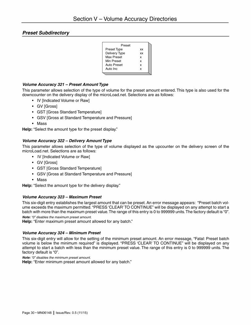
Page 30 • MN06148 Issue/Rev. 0.5 (11/15)
Section V – Volume Accuracy Directories
Preset Subdirectory
Volume Accuracy 321 – Preset Amount TypeThis parameter allows selection of the type of volume for the preset amount entered. This type is also used for the downcounter on the delivery display of the microLoad.net. Selections are as follows: • IV [Indicated Volume or Raw] • GV [Gross] • GST [Gross Standard Temperature] • GSV [Gross at Standard Temperature and Pressure] • MassHelp: “Select the amount type for the preset display.”
Volume Accuracy 322 – Delivery Amount TypeThis parameter allows selection of the type of volume displayed as the upcounter on the delivery screen of the microLoad.net. Selections are as follows: • IV [Indicated Volume or Raw] • GV [Gross] • GST [Gross Standard Temperature] • GSV [Gross at Standard Temperature and Pressure] • MassHelp: “Select the amount type for the delivery display.”
Volume Accuracy 323 – Maximum PresetThis six-digit entry establishes the largest amount that can be preset. An error message appears: “Preset batch vol-ume exceeds the maximum permitted. “PRESS ‘CLEAR’ TO CONTINUE” will be displayed on any attempt to start a batch with more than the maximum preset value. The range of this entry is 0 to 999999 units. The factory default is “0”.Note: “0” disables the maximum preset amount.Help: “Enter maximum preset amount allowed for any batch.”
Volume Accuracy 324 – Minimum PresetThis six-digit entry will allow for the setting of the minimum preset amount. An error message, “Fatal: Preset batch volume is below the minimum required” is displayed. “PRESS ‘CLEAR’ TO CONTINUE” will be displayed on any attempt to start a batch with less than the minimum preset value. The range of this entry is 0 to 999999 units. The factory default is “0”.Note: “0” disables the minimum preset amount.Help: “Enter minimum preset amount allowed for any batch.”
PresetPreset Type xxDelivery Type xxMax Preset xMin Preset xAuto Preset xAuto Inc x
Issue/Rev. 0.5 (11/15) MN06148 • Page 31
Section V – Volume Accuracy Directories
Volume Accuracy 325 – Auto PresetThis six-digit program code allows the operator to select the Auto Preset mode of operation for the microLoad.net. An entry of 0 disables this function and the preset amount used in the Run Mode will have to be either manually entered by the driver or entered through communications. An entry other than 0 (i.e., 1000) will result in the preset amount programmed in this code being used in the Run Mode. The microLoad.net will preset automatically at 1000 each time the “SET” button is pressed. The factory default is “0”.Note: “0” disables the Auto Preset.Help: “Select auto preset: a starting point for batch preset amounts.”
Volume Accuracy 326 – Auto Preset IncrementThis five-digit program code allows the operator to program a volume to be used as an incremental increase for the Auto Preset. The range of this entry is from 0 to 99999. The factory default is “0”.Example: Auto Preset is programmed for 1,000 units and the Auto Preset increment is programmed for 100 units. The driver/operator approaches the microLoad.net and goes through the necessary steps to get to the Preset Display.
Where: Premium = Programmed Product Name P = Preset 1000 = Volume programmed for Auto Preset Gal = Units of measurement
Driver presses SET. Volume will increment 100 units to 1100.Driver presses SET again. The volume will increment another 100 units to 1200.Driver continues pressing SET until the volume of product required is reached (i.e., 2000 gal).Help: “Enter amount to increment the auto preset volume with each press of the SET key.”

Page 32 • MN06148 Issue/Rev. 0.5 (11/15)
Section V – Volume Accuracy Directories
Prove Control Subdirectory
Volume Accuracy 331 – Auto Prove SelectThis parameter is used to enable or disable the Automated Proving Mode. The default for this program code will be disabled. Select one of the two (2) security options to enable the automated prove and associated security. Once selected and the security activated, the beginning of the next transaction will launch the auto prove. Once the prove is completed and the meter factor calculated, the operator has the choice of downloading the calculated meter factor into the software or ignoring it. The factory default is “Disabled.” Selections are as follows: • Disabled • Security input not required • Security input requiredCritical: Security input not configured.Help: “Select security level required for auto proving or disable auto proving.”
Volume Accuracy 332 – Proving CountersThis parameter defines whether microLoad.net is operating in a proving mode. In this mode the microLoad.net operates as in the Run Mode, except the preset and delivery counters both count up and go to tenths resolution. Volume preset and delivery units are in the volume units selected in the display units select code. The factory default is “Not Proving.” Selections are as follows: • Not proving • ProvingHelp: “Set downcounter to upcounter when proving.”
Prove Control
Auto Prove xxxxxProve Ctrs xxxxx

Issue/Rev. 0.5 (11/15) MN06148 • Page 33
Section V – Volume Accuracy Directories
Meter Factors Subdirectory
The “Meter Factor % Change/Degree” and “Meter Factor Variation Reference Temperature” program codes are only available if “Meter Factor Variation Select” is enabled.
Volume Accuracy 341 – Meter Factor 1 Volume Accuracy 343 – Meter Factor 2 Volume Accuracy 345 – Meter Factor 3 Volume Accuracy 347 – Meter Factor 4
These program codes and the associated flow rates below allow the entry of the meter factor curve. The microLoad.net will perform linearization to calculate meter factors between the entered flow rates.If only a single meter factor is used, it must be put into program code 302. The flow rate selected in program code 303 or 305 must be set to “0”. Under these conditions any other meter factors programmed will be ignored. The range of these six-digit numeric entries is 0 to 9.99999.Note: A zero entry in meter factor 1 will be considered an invalid entry. Zero entries in the remaining factors will result in that factor and subsequent factors that are not being used. (e.g., if a zero entry is made for factor 2, factors 3 and 4 will not be used.)Fatal: Entry must not be zero [341 only].Critical: Factor varies more than the Linearized Factor Deviation.Critical: Meter factors must be within 2% of the master meter factor.Help: “Meter factor = (actual volume x current factor x k factor)/input pulses.”
Volume Accuracy 342 – Flow Rate 1 Volume Accuracy 344 – Flow Rate 2 Volume Accuracy 346 – Flow Rate 3 Volume Accuracy 348 – Flow Rate 4These five-digit entries are the flow rates at which the meter factors (codes 302, 304, 306, 308) are defined beginning with the highest flow rate in program code 303 and descending to the lowest flow rate in program code 309. If only one meter factor is used, program code 303 or 305 must be set at “0”. The range of these entries is 0 to 99999 flow units.Critical: Flow rates must be entered in descending order.Critical: Corresponding meter factor not programmed.Help: “Enter the flow rate corresponding to the meter factor, mass or vol based on pulse input type.”
Meter FactorsMtr Factor xxxxxFlow Rate 1 xxxMtr Factor 2 xxxxxFlow Rate 2 xxxMtr Factor 3 xxxxxFlow Rate 3 xxxMtr Factor 4 xxxxxFlow Rate 4 xxxMaster Mtr Fact xxxxxLinear Factor Dev xxxxxMF Var Select xxxxxMF % Change/Deg xxxMF Var Ref Temp xxx
Page 34 • MN06148 Issue/Rev. 0.5 (11/15)
Section V – Volume Accuracy Directories
Volume Accuracy 349 – Master Meter FactorThis program code allows the operator to set a master meter factor. This six-digit entry will be used to restrict meter factors one through four (codes 341, 343, 345 and 347), to plus or minus 2% of the master factor (i.e., the value entered here). This range restriction applies only to meter factors which are programmed for use (i.e., meter factor one always and, if linearizing, all the factors used). Any attempt to enter a meter factor outside the 2% range, if installed, will cause a Critical Warning.In addition, a master factor entry that causes the current meter factors installed to be out of range will cause those meter factors which are out of range to prompt a Critical Message. This critical condition must be corrected so that all used meter factors are within the 2% range of the master factor before normal Run Mode operations can occur. The range of this entry is 0 to 9.99999. Note that zero disables the master meter factor.Critical: Meter factor must be within 2% of the master meter factor.Help: “Restricts programmed meter factors to + or –2% of this master factor.”
Volume Accuracy 350 – Linearized Factor DeviationThis code allows the operator to set a maximum deviation between adjacent meter factors. This three-digit entry will be used to restrict deviation between the adjacent meter factors in use to plus or minus the entered percentage (i.e., the value entered here). Any attempt to enter a meter factor outside the entered range will cause a Critical Warning.A linearized factor deviation entry that results in the current meter factors installed to be out of range will set a program code alarm. The meter factors that are out of range will be indicated by a DA alarm. The meter factors at fault must be corrected so they are within range of the deviation entry before normal Run Mode operations can occur. The value of the linearized factor deviation may range from 0 to 9.99%. Zero disables this feature.Critical: Meter factor varies more than the Linearized Factor Deviation.Help: “Set the maximum deviation in percent allowed between adjacent meter factors.”
Volume Accuracy 351 – Meter Factor Variation SelectThis parameter allows the selection of enabling or disabling the meter factor variation entries (calculations). When enabled the microLoad.net will calculate and use the meter factors based on the current temperature of the product. The factory default is “Disabled.” Selections are as follows: • Disabled • EnabledNote: No entry if temperature units not assigned.Critical: Security level for parameter must be at top 2 levels. Help: “Enable or disable the use of meter factor variation with temperature.”
Volume Accuracy 352 – Meter Factor Percent Change Per Degree TemperatureThis four-digit parameter allows the entry of the meter factor variation with temperature. This four-digit entry represents the meter factor percent change per degree of temperature. The range of this parameter is 0.0001 to 0.9999 percent. Fatal: Entry is out of specified range.Help: “Enter the meter factor variation in % change per degree temperature.”
Volume Accuracy 353 – Meter Factor Variation Reference TemperatureThis four-digit code allows the entry of the meter factor reference temperature. This entry represents the temperature, in tenths, at which the present meter factor was determined. The range of this entry is 000.1 to 999.9 units.Fatal: Entry is out of specified range.Help: “Enter reference temperature for the meter factor % change per degree.”

Issue/Rev. 0.5 (11/15) MN06148 • Page 35
Section V – Volume Accuracy Directories
Mass Meter Subdirectory
Volume Accuracy 361 – Mass Meter TypeThis parameter allows the operator to select the mass meter used by the meter. The factory default is “NA.” Selections are as follows: • NA • S-Mass • Apollo • PromassHelp: “Select the type of mass meter, S-Mass, Apollo or Promass.”
If a mass meter is selected the Mass Meter Subdirectory is expanded to include mass meter data.
Volume Accuracy 362 – Mass Meter Sequence NumberThis entry allows the operator to enter the specific sequence number assigned to a mass meter connected to the microLoad.net. The range of this entry is from 0 to 99999.Help: “Last five digits of the Micro-Pak serial number, the Final Assembly # for Apollo or address for Promass.”
Volume Accuracy 363 – S-Mass Coefficient KaThis entry allows the operator to enter the Constant Ka from the S-Mass meter. This numeric entry has a range of 0.0000 to 63.99999. This parameter specifies the “Ka” value in the equation KaX2+KbX + Kc = Density. See MN0M008 for more information.Note: No entry if not selected as installed densitometer type.Help: “Enter the Ka from the S-Mass nameplate.”
Volume Accuracy 364 – S-Mass Coefficient KbThis entry allows the operator to enter the Constant Kb from the S-Mass meter. This numeric entry has a range of -31.9999 to 31.9999. This parameter specifies the “Kb” value in the equation KaX2+KbX + Kc = Density. See MN0M008 for more information.Note: No entry if not selected as installed densitometer type.Help: “Enter the Kb from the S-Mass nameplate.”
Mass Meter
Type xxSequence # x
Mass MeterType xxSequence # xCoeff Ka x.xxxxCoeff Kb x.xxxxCoeff Kc x.xxxxDensity Factor xPulse Mult xxLow Flow Cutoff xxTube Material xxxxxSensor Model xx

Page 36 • MN06148 Issue/Rev. 0.5 (11/15)
Section V – Volume Accuracy Directories
Volume Accuracy 365 – S-Mass Coefficient KcThis entry allows the operator to enter the Constant Kc from the S-Mass meter. This numeric entry has a range of -31.9999 to 31.9999. This parameter specifies the “Kc” value in the equation KaX2+KbX + Kc = Density. See MN0M008 for more information.Note: No entry if not selected as installed densitometer type.Help: “Enter the Kc from the S-Mass nameplate.”
Volume Accuracy 366 – S-Mass Density Factor This factor is used to adjust the period of the tubes for the minute changes in tube frequency that occurs with change in the flow rate. This factor is typically not changed in the field. The setting depends on the sensor size and materials of construction. Factory settings are as follows:
Stainless Steel Hastelloy
S25LF N/A 030
S25 N/A 030
S50 020 028
S100 016 023
S200 019 027
If the Density Factor for your sensor is different from what is shown, consult your Smith Meter representative.Note: No entry if not selected as installed densitometer type. Help: “Enter the Density Factor for the S-Mass.”
Volume Accuracy 367 – Mass Meter Pulse MultiplierThe mass meter flow rate pulse output is multiplied by this factor to increase the number of pulses per unit of volume resolution. The maximum frequency for the flow rate pulse output is 2500 Hz. Selections are as follows: • x 1 • x 2 • x 4 • x 8 • x 16 • x .5Note: No entry if not selected as installed densitometer type.Help: “Enter the multiplier for the flow pulse output 1, 2, 4, 8, 16, or .5.”
Volume Accuracy 368 – Mass Meter Low Flow Cutoff This entry allows the operator to specify the low flow cutoff point. The range of this numeric entry is from 0 to 99. This is the Low Flow Cutoff for the S-Mass meter. The range is 0 to 99. A value of 10 approximates 1.0% of full scale flow, 20 approximates 2.0% of full flow etc. This function prevents counting extraneous pulses that may be generated while at no flow condition. Factory default is 20. See MN0M008 for more information.Note: No entry if not selected as installed densitometer type.Help: “Enter the min. flow to report. 10 = 1% of full scale flow.”

Issue/Rev. 0.5 (11/15) MN06148 • Page 37
Section V – Volume Accuracy Directories
Volume Accuracy 369 – Mass Meter Tube MaterialThis entry allows the operator to specify the type of material from which the mass meter’s tubes were constructed. Selections are as follows: • Stainless • HastelloyNote: No entry if not selected as installed densitometer type.Help: “Select the tube material (stainless or hastelloy) for this meter.”
Volume Accuracy 370 – Mass Meter ModelThis entry allows the operator to specify the type of sensor contained in the mass meter. Selections are as follows: • Model 25 • Model 50 • Model 100 • Model 200Note: No entry if not selected as installed densitometer type.Help: “Select the sensor model of the meter.”

Page 38 • MN06148 Issue/Rev. 0.5 (11/15)
Section VI – Temperature/Density Directories
Temperature Subdirectory
Temperature/Density 401 – Temperature UnitsThis program code selects the temperature scale used by microLoad.net. The factory default is “NA.” Selections are as follows: • NA • Fahrenheit • CelsiusCritical: API table conflicts with selected units.Help: “Select temperature units.”
Temperature/Density 402 – Reference TemperatureThe actual uncompensated volume throughput is temperature compensated to its equivalent volume at this four-digit reference temperature in tenth degrees. The most common reference temperatures are 60.0 Deg. F and 15.0 Deg. C. The range of this entry is 0.0 to 999.9.Note: No entry if Temperature Units = Not Used.Help: “Used as base for correction of liquid volume.”
Temperature/Density 403 – Maintenance Temperature This code allows the entry of a maintenance temperature to be used when a temperature probe is not installed or working, but temperature related calculations are desired. The temperature units are dependent on the entry made in the Temperature Units Select code. This four-digit entry has a range of –999.9 to 999.9 temperature units where –999.9 disables the maintenance temperature. Note: An entry greater than -999.9 will override the temperature probe or transducer input if installed and will be used in all calculations where temperature is used.Note: No entry if Temperature Units = Not Used.Help: “Select maintenance temperature if temperature probe is not installed or to override probe.”
Temperature/Density 404 – High Temperature Alarm LimitThis code allows the entry of a temperature reading that will cause a high temperature alarm to be generated. The temperature units will be dependent on the entry made in the Temperature Units Select code. This four-digit entry has a range of –999.9 to +999.9 degrees F or C. Note: An entry of “+999” will disable the alarm. Help: “Enter temperature that will cause an alarm for high temperature.”
Temp/Dens Dir
TemperatureDensity
Temperature
Temp Units xRef Temp xx.xMaint Temp xx.xHi Temp Alarm xxxLo Temp Alarm xxx
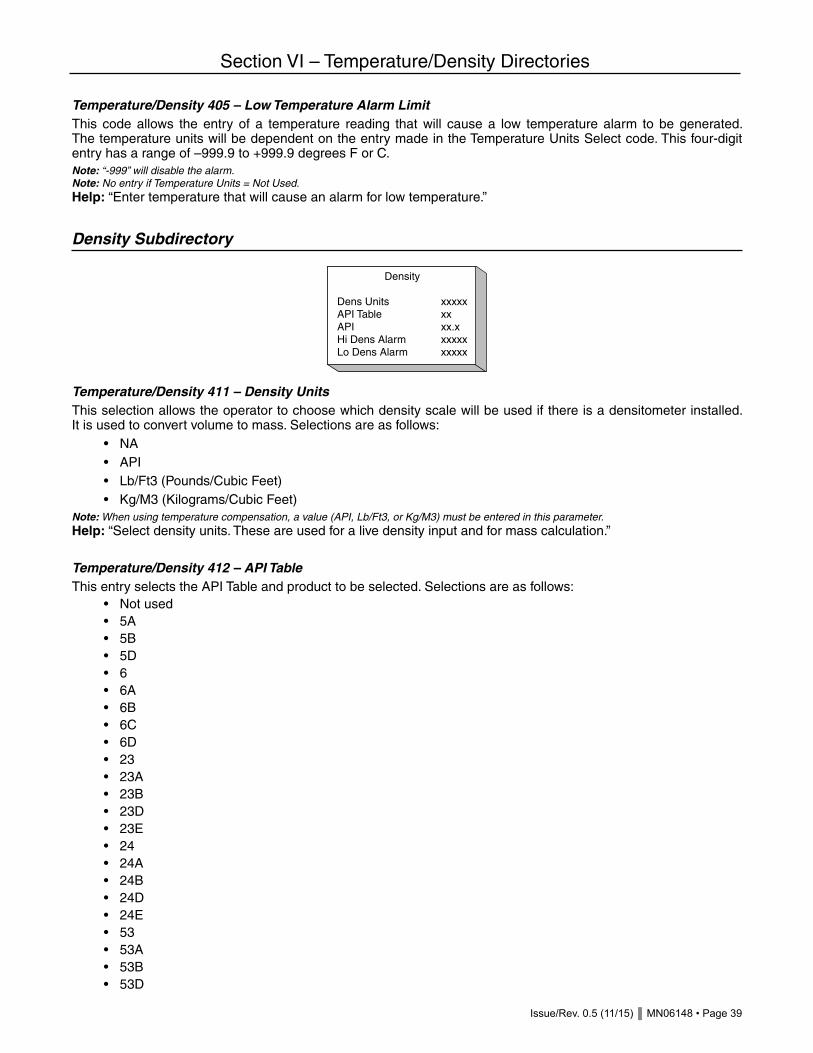
Issue/Rev. 0.5 (11/15) MN06148 • Page 39
Section VI – Temperature/Density Directories
Temperature/Density 405 – Low Temperature Alarm LimitThis code allows the entry of a temperature reading that will cause a low temperature alarm to be generated. The temperature units will be dependent on the entry made in the Temperature Units Select code. This four-digit entry has a range of –999.9 to +999.9 degrees F or C. Note: “-999” will disable the alarm.Note: No entry if Temperature Units = Not Used.Help: “Enter temperature that will cause an alarm for low temperature.”
Density Subdirectory
Temperature/Density 411 – Density UnitsThis selection allows the operator to choose which density scale will be used if there is a densitometer installed. It is used to convert volume to mass. Selections are as follows: • NA • API • Lb/Ft3 (Pounds/Cubic Feet) • Kg/M3 (Kilograms/Cubic Feet)Note: When using temperature compensation, a value (API, Lb/Ft3, or Kg/M3) must be entered in this parameter.Help: “Select density units. These are used for a live density input and for mass calculation.”
Temperature/Density 412 – API TableThis entry selects the API Table and product to be selected. Selections are as follows: • Not used • 5A • 5B • 5D • 6 • 6A • 6B • 6C • 6D • 23 • 23A • 23B • 23D • 23E • 24 • 24A • 24B • 24D • 24E • 53 • 53A • 53B • 53D
Density
Dens Units xxxxxAPI Table xxAPI xx.xHi Dens Alarm xxxxxLo Dens Alarm xxxxx

Page 40 • MN06148 Issue/Rev. 0.5 (11/15)
Section VI – Temperature/Density Directories
• 54 • 54A • 54B • 54C • 54D • BR1A • BR1P • BR2P • 59A • 59B • 59D • 60A • 60B • 60D • NH3 • 53E • 54E • 59E • 60E • Eth/Gas (PTB) • Aromatic
Critical: API table conflicts with temperature units.Critical: No density input configured [odd tables only].Note: No entry if Temperature Units = Not Used.Help: “Select the API table to be used for temperature compensation.”Note: Tables BR1A, BR1P, and BR2P are Brazilian tables. Tables 59A, 59B, 59D, 60A, 60B, and 60D are ISO 91-2 correction tables.
Temperature/Density 413 – Reference Density This code has a constant five-digit entry with a floating decimal point. The format is based on table and product selection. The program code format and data entry allows the programmable entry of the Reference Density when Table 54 is selected, Relative Density when Table 24 is selected, API when Table 6 is selected, and temperature coefficient when a C Table is selected. This entry represents the reference value used to calculate the volume correction factor. The range of this value will vary with the table selection chosen.Note: When Table 6 is selected, the leading digit will be used to show polarity, + = positive and a - = negative.Entry range is based on table selection.
Table 6 -999.9 to +999.9 APITable 24 0 to 9.9999 Relative DensityTable 54 0 to 9999.9 Reference DensityC Tables 0 to 0.9999 Percent per Degree TemperatureNote: If the API table selection is changed, the previous five-digit entry for reference will not be converted. This value must be re-entered.
The following are examples of the display when Tables 24, 54 or 6C and 54C are selected.
Table 6B selected: +43.2 APITable 24 selected: 0.8175 Rel DensityTable 54 selected: 1150.2 Kg/M3Table 6C or 54C selected: 0.0800 %/Deg. F or Deg. CFatal: Entry is out of specified range.

Issue/Rev. 0.5 (11/15) MN06148 • Page 41
Section VI – Temperature/Density Directories
Note: No entry if Density Units = Not Used.Note: No entry if API table is odd.Help: “Enter the product density at reference temperature or the temperature coefficient (for C tables).”
Temperature/Density 414 – High Density Alarm LimitThis code allows the entry of a density reading that will cause a high-density alarm to be generated. The units will be dependent on the entry made in the Density Units Select code. This four-digit entry will be dependent on the API table selection as follows: –999.9 to +999.9 API0.000 to 9999.0 Reference DensityNote: No entry if Density Units = Not Used.Help: “Enter density that will signal an alarm for high product density.”
Temperature/Density 415 – Low Density Alarm LimitThis code allows the entry of a density reading that will cause a low-density alarm to be generated. The units will be dependent on the entry made in the Density Units Select code. This five-digit entry will be dependent on the API table selection as follows: –999.9 to +999.9 API0.000 to 9999.0 Reference DensityNote: No entry if Density Units = Not Used.Help: “Enter density that will signal an alarm for low product density.”
Temperature/Density 416 – % Weight H2OThis program code is used as an input to the NH3 compensation tables only. It is required to more accurately correct for ammonia’s change in volume over temperature. This five-digit entry will be dependent on the API table selection as follows: 0.000 to 10.000Help: “Enter the percentage of water (by weight) in the product being delivered.”
Temperature/Density 417 – Reference Density's TemperatureThis program code allows specifying the reference density’s base temperature. For example, the reference density’s base temperature could be 15°C while volume is to be corrected to 30°C. If 0 is entered, it is assumed that the refer-ence density’s base temperature is the same as the programmed reference temperature (parameter 402).Help: “Enter base temperature for reference density. If 0, parameter 402 Ref Temp is used.”
Temperature/Density 418-420 – Ethanol Coefficient°These program codes are required/used only with the Eth/Gas (PTB) API table selection, which is a calculation method required for use when metering pre-blended ethanol/gasoline mixture in some markets. The entry is dependent on the percentage of ethanol in the blend. PTB specifies certain coefficients be used for specific ratios of gasoline/ethanol. Currently only the following coefficients for commonly encountered ethanol blend percentages are defined:
RatioRef Density* A1 A2 A3
E5738.858 -1.2422 x 10⁻³ -9.1811 x 10⁻⁷ -5.3906 x 10⁻⁹
E10741.447 -1.2415 x 10⁻³ -9.8712 x 10⁻⁷ -6.633 x 10⁻⁹
E80781.410 -1.1129 x 10⁻³ -6.5049 x 10⁻⁷ -8.8556 x 10⁻⁹
E85784.549 -1.1023 x 10⁻³ -6.0110 x 10⁻⁷ -8.7249 x 10⁻⁹

Page 42 • MN06148 Issue/Rev. 0.5 (11/15)
Section VI – Temperature/Density Directories
Valid Range: (-1.00000 x 1037 to 1.00000 x 1038)*Reference Density (Kg/m3) of mixture at 15°C. This value should be entered in Temperature/Density parameter 413. Reference density at 15°C in units of kg/m3 should be entered regardless of programmed density units or reference temperature.Help: “Enter the coefficients for the ethanol/gasoline blend.”
Temperature/Density 421 – Aromatic Hydrocarbon ProductThis program code specifies the industrial aromatic hydrocarbon or cyclohexane product being delivered. Temperature compensation will be performed according to the ASTM D 1555 standard. This entry is only applicable if API table (parameter 412) is programmed for “Aromatic” and temperature units (parameter 401) are programmed. For impure products, parameter 422 may be used to enter the density of the mixture. Otherwise, the density of the pure product will be used in the calculations. Selections are as follows: • 00 Benzene • 01 Cumene • 02 Cyclohexane • 03 Ethylbenzene • 04 Styrene • 05 Toluene • 06 m-Xylene • 07 o-Xylene • 08 p-Xylene • 09 300-350° Aromatic • 10 350-400° AromaticHelp: “Select the ASTM D 1555 aromatic hydrocarbon product to be delivered.”
Temperature/Density 422 – Aromatic Hydrocarbon Reference DensityThis parameter is used to enter the reference density of an aromatic hydrocarbon product that is considered impure. If 0 is entered, the density of the pure product will be used in the calculations. Reference density should be entered in density units of kg/m3 and should be based at the programmed reference temperature (parameter 402) or the reference density’s temperature (parameter 417). The range of this entry is 0.00 to 9999.99.Note: If “300-350° Aromatic” or “350-400° Aromatic” product is selected, the reference density for the product must be entered. Otherwise, the conversion of volume and mass will not be available. (i.e. if volume pulse input, mass will not be available. If mass pulse input, volume will not be available). Help: “Enter reference density (kg/m3) of impure product. If 0 entered, density of pure product will be used.”
Temperature/Density 423 – Reference Density for C TablesWhen a C Table is used, the reference density parameter 413 is used to enter the coefficient of thermal expansion. This program code is used to calculate mass when using a C Table. This special density allows C Tables to have a reference density which enables mass to be computed when live density is not available. The range of this entry is -9999.9 to +9999.9.Help: “Enter ref density used to calculate mass when using a C Table. Enter in units per parameter 411.”

Issue/Rev. 0.5 (11/15) MN06148 • Page 43
Section VII – Pressure Directories
General Purpose Subdirectory
The subdirectory is used to provide general information regarding the setup of the microLoad.net for pressure as-pects. If “Pressure Units” program code is set to “NA”, the remaining codes in this subdirectory will not be available.
Pressure 501 – Pressure UnitsThis parameter defines the pressure units used by microLoad.net. The factory default is “NA.” Selections are as follows: • NA • PSI • Bar • Kg/cm2 (Kilograms/square centimeter) • Kpa (kilopascals)Help: “Select units of pressure.”
Pressure 502 – Maintenance PressureThis code allows the entry of a maintenance pressure to be used when a pressure transmitter is not installed or is not working, but pressure-related calculations are desired. The pressure units will be dependent on the entry made in the Pressure Units Select code (Pressure 501). This five-digit entry has a range of 0.0 to 9999.9 pressure units. A non-zero value entered here will override an analog pressure input.Note: No entry if Pressure Units = NA.Help: “Select pressure to be used in CPL calculation.”
Pressure 503 – Pressure Coefficient This code will allow for the entry of a Compressibility Factor that will be used by the system to calculate the CPL. This entry should be zero if a densitometer is installed or a reference density is entered. In these cases, the microLoad.net will calculate the compressibility factor. If, however, API table 6C or 54C is selected, then a compressibility factor must be entered here if pressure compensation is desired, as the microLoad.net has no density with which to calculate the compressibility factor. The factor is used as the following: XXXXX equals the factor entered and it is applied as 0.0000XXXXX.Note: This value will represent the “F” variable in the CPL equation.Note: No entry if Pressure Units = NA.Help: “Enter compressibility factor used to calculate CPL [where 0.0000XXXXX is the compressibility factor].”Pressure
504 – High Pressure Alarm LimitThis code allows the entry of a pressure reading that will cause a high pressure alarm to be generated. The pressure units will be dependent on the entry made in the Pressure Units Select code. This four-digit entry has a range of 0.0 to +9999.
Pressure Dir
General PurposeBack PressureVapor Pressure
General Purpose
Pressure Units xxxMaint Pres xxxPres Coeff xxxHi Pres Alarm xxLo Pres Alarm xx

Page 44 • MN06148 Issue/Rev. 0.5 (11/15)
Section VII – Pressure Directories
Note: An entry of “+9999” will disable the alarm.Note: No entry if Pressure Units = NA.Help: “If pressure exceeds this value an alarm will occur.”
Pressure 505 – Low Pressure Alarm LimitThis code allows the entry of a pressure reading that will cause a low pressure alarm to be generated. The pressure units will be dependent on the entry made in the Pressure Unit Select code. This four-digit entry has a range of 0.0 to +9999. Note: “9999” will disable the alarm.Note: No entry if Pressure Units = NA.Help: “If pressure drops below this value an alarm will occur.”
Pressure 506 – Ambient PressureThis program code allows for the entry of an ambient pressure value to be used to correct gauge pressure to absolute pressure. This value is used in the NH3 correction calculation for anhydrous ammonia.Help: “Enter the ambient pressure to correct gauge pressure to absolute pressure.”
Back Pressure Subdirectory
Pressure 511 – Minimum Back Pressure Flow Rate TimerThis two-digit entry will allow the operator to select the minimum time, in seconds, allowed for the unit to achieve a desired flow rate. If the flow rate is not reached in this time, the flow rate will be lowered by Back Pressure Percent Reduction to increase back pressure. If the flow rate falls below the back pressure minimum flow, an alarm will be issued and the valve will be closed. The range of this entry will be 0 to 99 seconds.Note: This entry is used for Automatic Flow Optimization (AFO).Note: “00” disables any back-pressure control (including the differential pressure method.)Help: “Minimum time in seconds to reach desired flow rate during BP control.”
Pressure 512 – Back Pressure Percent ReductionThis two-digit entry will allow the operator to select the percentage of flow rate to be used during insufficient back pressure conditions. (For example, an entry of 90% will cause the flow rate to be reduced to 90% of the current rate during insufficient back pressure conditions.) The range of this entry is 50 percent to 90 percent.Note: This entry is used for Automatic Flow Optimization (AFO).Help: “In BP control, the flow rate will be reduced to this percentage of the current flow rate. Range is 50% to 90%.”
Pressure 513 – Minimum Back Pressure Flow RateThis four-digit entry will allow the operator to select the Minimum Back Pressure Flow Rate that will not cause an alarm. That is, any time the flow rate is being controlled because of insufficient back pressure and it falls below this programmed rate, a back pressure alarm will be issued and the valve will be closed. The range of this entry will be 0 to 9999.Help: “Min flow rate allowed during BP control before alarm, mass or vol based on pulse input type.”
Back PressureBP Flow Timer xxBP % Reduction xxMin Flow Rate xxxFlo Recover Time xxDiff Pressure xxFlo Recover Pres xxx

Issue/Rev. 0.5 (11/15) MN06148 • Page 45
Section VII – Pressure Directories
Pressure 514 – Back Pressure Flow Recovery TimerThis two-digit numeric entry programs the amount of time the microLoad.net will wait to attempt flow rate recovery if a pressure reading is not available in the system. The range of this timer is from 0 to 99 minutes. Zero will disable the flow recovery feature. This parameter provides a method of flow recovery that does not require the use of a pressure transmitter input.Help: “Enter the time interval in minutes to attempt flow recovery.”
Pressure 515 – Differential PressureThis four digit entry will allow the operator to select the delta pressure in PSIA, bars, kPa,or kg/cm2 (units depend upon the Pressure Units select entry (Pressure 501). This is the additional pressure to be maintained above the vapor pressure. If microLoad.net is controlling flow with a two stage valve, no alarm is issued and flow is not halted if the pressure drops below the programmed limit determined by vapor pressure and differ-ential pressure. Therefore this differential pressure feature should not be used with a two stage valve. In this situation, the low pres-sure alarm must be set high enough to ensure that the pressure does not fall below the product’s vapor pressure.
The range of this entry is 0-9999 pressure units. An entry of “0” will disable pressure control of the valve by a pressure transducer.Note: A non-zero entry here will override ant other programmed type back pressure flow control.Note: No entry if Pressure Units = NA.Help: “Enter back pressure to be maintained above the product vapor pressure.”
Pressure 516 – Flow Recovery PressureThis four digit entry allows the programming of the amount of pressure above the vapor pressure of the product that must be read by the microLoad.net before it will attempt flow recovery to the programmed high flow. This parameter is used in conjunction with a pressure transmitter input. Note: This pressure must be sufficiently higher than the Differential Pressure entered in Pressure 515 to prevent flow rate oscillation.
The range of this entry is 0-9999 pressure units.Help: “Enter the differential; pressure above vapor pressure to attempt flow recovery.”VAPOR PRESSURE SUBDIRECTORYNote: Pressure and temperature data, points 1,2,3 (Pressure 522-527) are only activated if “Straight Line Approximation” is selected as the “Vapor Pressure Calculation Method”.
Pressure 521 – Vapor Pressure Calculation MethodThis parameter defines the method that the microLoad.net will use to calculate the vapor pressure of a product. Selections are as follows: • Straight Line Approximation (Requires points of the curve to be entered in codes 522 through 527). • As outlined in GPA TP-15 (Gas Processors Association Technical Publication 15). (Uses the reference density of the product in the calculations).
Critical: GPA-TP15 requires corrected density [temperature used, API table selected].Help: “Choose vapor pressure calculation method.”
Vapor PressureVP Calc xxxxxVapor Pres 1 xxxVP Temp 1 xxVapor Pres 2 xxxVP Temp 2 xxVapor Pres 3 xxxVP Temp 3 xx

Page 46 • MN06148 Issue/Rev. 0.5 (11/15)
Section VIII – Alarm Directories
Pressure 522, 524, 526 – Vapor Pressure 1, 2, 3These three codes allow the operator to select the vapor pressures, which are used to define the vapor pressure versus temperature curve. This curve is used to calculate the current vapor pressure. The pressure(s) are defined beginning with the lowest pressure ascending to the highest pressure. The range of these five-digit numeric entries is 0000.0 to 9999.9 pressure units. The unit for this entry is dependent on the entry made in the Pressure Units Select Code. The vapor pressure calculation, determined from the entries made here, will be used both for differential back pressure control and in the CPL equation as the “Pe” entry. Therefore, careful consideration should be given in determining these points and their accuracy. Critical: Vapor pressures must be entered in ascending order.Note: No-entry if Vapor Pressure Calculation Method = GPA-TP15.Help: “Enter vapor pressure at corresponding product temperature.”
Pressure 523, 525, 527 – Vapor Pressure Temperature 1, 2, 3These three codes, with three-digit numeric entries, allow the operator to select the temperatures that will be used to define the vapor pressure versus temperature curve. This curve is used to calculate the current vapor pressure. These temperatures correspond with the vapor pressures. The range of these entries is –999 degrees to +999 degrees. The units for these entries are as programmed in the Temperature Units Select Code. The vapor pressure calculation, determined from the entries made here, will be used both for differential back pressure control and in the CPL equation as the “Pe” entry. Therefore, careful consideration should be given in determining these points and their accuracy. Critical: Corresponding vapor pressure not programmed.Note: No entry if Vapor Pressure Calculation Method = GPA-TP15.Help: “Enter product temperature at corresponding vapor pressure.”

Issue/Rev. 0.5 (11/15) MN06148 • Page 47
Section VIII – Alarm Directories
Alarm 601 – Driver Clearable AlarmsThis parameter sets the number of alarms that can be cleared without a passcode. It is a two-digit entry with a range of 0-20.Help: “Enter the number of alarms clearable not requiring a passcode.”
Alarm 602 – Powerfail AlarmThis program code provides the operator with the capability of either enabling or disabling the powerfail alarm. The powerfail alarm is a diagnostic alarm that is not clearable through communications. The factory default for this parameter is “Yes”. Selections are as follows: • Yes • NoHelp: “Select if an alarm indicating loss of power is desired.”
Configure Alarms Directory
Alarm 611 to 675 – Alarm ConfigurationThese parameters allow the actions of each alarm to be configured. Multiple options selected from the following list may be configured for each alarm. The microLoad.net treats all alarm configured to an action as being logically “OR”ed. i.e. If any of the alarms assigned to action are energized, the action is energized. Selections are as follows: • Allow run/ready clearing • Energize alarm output 1 • Energize alarm output 2Note: Through Communications, add to get combination of desired options (i.e., 7 would set up all three options.)Note: For more information about alarm messages and their equivalent in Blend-Pak injectors, Mini-Pak injectors, and metered injectors, refer to Appendix I – Alarms.The following examples illustrate the steps required to establish and view the configuration of alarms in a microLoad.net. The Communications Alarm is used for the example, but the steps are typical of any alarm.
Configuring Alarm Actions
611 CommRun/Ready Clear
YesNo
System Alarms
611 Comm612 Ticket613 PTB Printer614 Shared Printer615 Report Storage Full616 Network Printer
System Alarms611 Comm
View ActionConfigure Action
611 Comm
Run/Ready ClearEnable Alarm Out 1Enable Alarm Out 2
Alarm Dir
System AlarmsFlow AlarmsTemp/Dens AlarmsMeter AlarmsInjector AlarmsUser AlarmsUser Alarm Messages
Alarm Dir
Driver Clearable xxPwrfail Alarm xxConfigure Alarms

Page 48 • MN06148 Issue/Rev. 0.5 (11/15)
Section VIII – Alarm Directories
• From the “System Alarms” subdirectory select “611 Comm”, press ENTER • Select “Configure Action”, press ENTER • Select desired action, press ENTER (Actions already selected will be marked with an *) • Select “Yes” to enable the action or “No” to disable the action, press ENTER • The microLoad.net returns to the previous screen for another selection, repeat or press CLEAR to return to the first screen of the selected alarm subdirectory.
Viewing Alarm Actions
• From the “System Alarms” subdirectory select “611 Comm”, press ENTER • Select “View Action”, press ENTER • The microLoad.net displays a list of enabled actions for the alarm. Press CLEAR to return to the first screen of the selected alarm subdirectory.
System Alarms Subdirectory
611 CM: Communications Alarm. Indicates a failure on one of the communication channels.612 TK: Ticket Alarm. Indicates a removal of the ticket from the Load Printer was tried during the batch. When the alarm is received, press PRINT to clear the transaction.613 PP: PTB Printer Failure Alarm. Indicates that the microLoad.net failed to receive the correct response from the PTB printer after the data was sent to be printed. The microLoad.net will continue to resend the data to the printer until the communication port timeout setting expires, the PTB printer alarm will be set at this time.614 SP: Shared Printer Failure Alarm. This alarm occurs if a shared printer is configured and the microLoad.net is unable to arbitrate for the printer within the timeout programmed for the shared printer port in the Communications directory.615 RP: Report Storage Full Alarm. If the driver attempts to start a transaction from the microLoad.net keypad and it would require overwriting a pending transaction report, the following alarm will be set and the transaction will not be allowed to be started.616 NP: Network Printer Alarm. The network printer alarm will occur when a printer error occurs and the Printer Standby (System 740) is not set to silent standby.
System Alarms
611 Comm612 Ticket613 PTB Printer614 Shared Printer615 Report Storage Full616 Network Printer
611 Comm
Run/Ready Clear
System Alarms
611 Comm612 Ticket613 PTB Printer614 Shared Printer615 Report Storage Full616 Network Printer
System Alarms611 Comm
View ActionConfigure Action
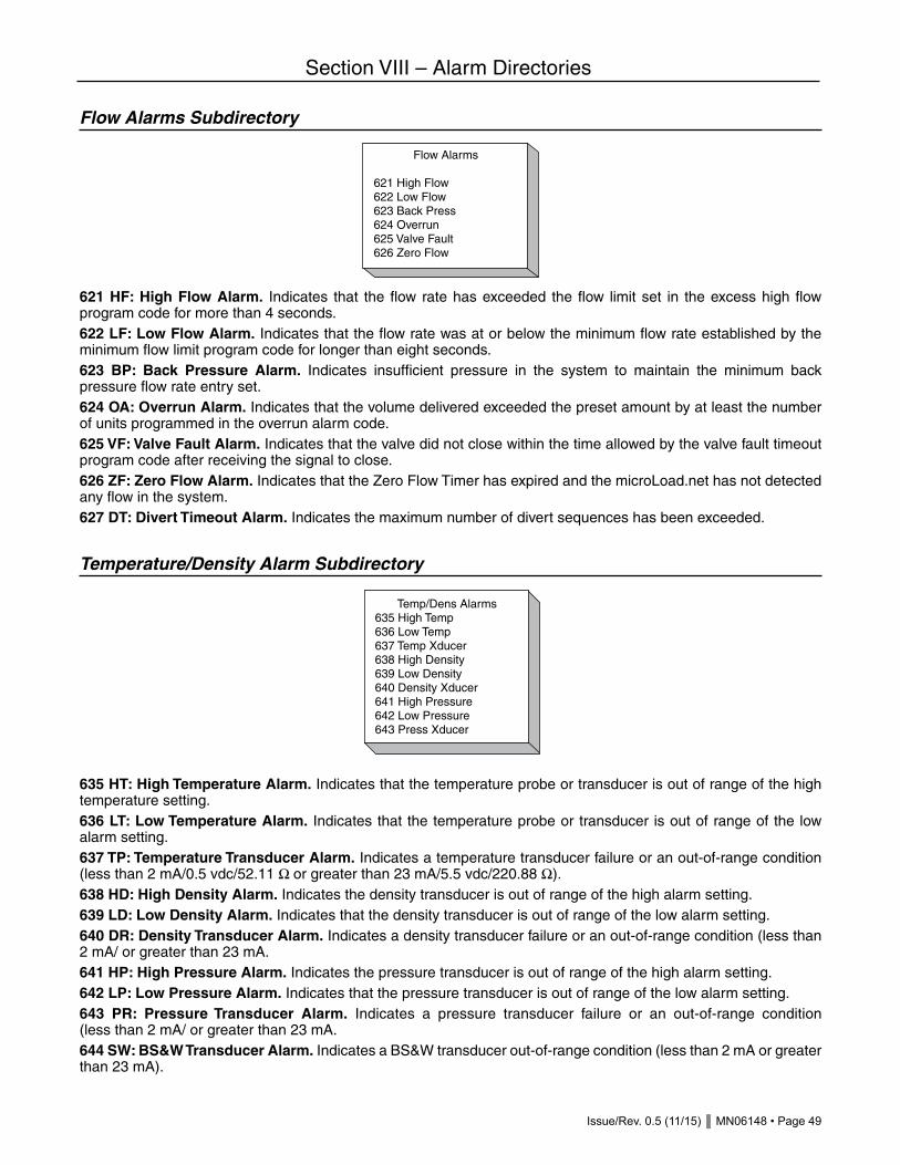
Issue/Rev. 0.5 (11/15) MN06148 • Page 49
Section VIII – Alarm Directories
Flow Alarms Subdirectory
621 HF: High Flow Alarm. Indicates that the flow rate has exceeded the flow limit set in the excess high flow program code for more than 4 seconds.622 LF: Low Flow Alarm. Indicates that the flow rate was at or below the minimum flow rate established by the minimum flow limit program code for longer than eight seconds.623 BP: Back Pressure Alarm. Indicates insufficient pressure in the system to maintain the minimum back pressure flow rate entry set.624 OA: Overrun Alarm. Indicates that the volume delivered exceeded the preset amount by at least the number of units programmed in the overrun alarm code.625 VF: Valve Fault Alarm. Indicates that the valve did not close within the time allowed by the valve fault timeout program code after receiving the signal to close.626 ZF: Zero Flow Alarm. Indicates that the Zero Flow Timer has expired and the microLoad.net has not detected any flow in the system. 627 DT: Divert Timeout Alarm. Indicates the maximum number of divert sequences has been exceeded.
Temperature/Density Alarm Subdirectory
635 HT: High Temperature Alarm. Indicates that the temperature probe or transducer is out of range of the high temperature setting.636 LT: Low Temperature Alarm. Indicates that the temperature probe or transducer is out of range of the low alarm setting.637 TP: Temperature Transducer Alarm. Indicates a temperature transducer failure or an out-of-range condition (less than 2 mA/0.5 vdc/52.11 Ω or greater than 23 mA/5.5 vdc/220.88 Ω).638 HD: High Density Alarm. Indicates the density transducer is out of range of the high alarm setting.639 LD: Low Density Alarm. Indicates that the density transducer is out of range of the low alarm setting.640 DR: Density Transducer Alarm. Indicates a density transducer failure or an out-of-range condition (less than 2 mA/ or greater than 23 mA.641 HP: High Pressure Alarm. Indicates the pressure transducer is out of range of the high alarm setting.642 LP: Low Pressure Alarm. Indicates that the pressure transducer is out of range of the low alarm setting.643 PR: Pressure Transducer Alarm. Indicates a pressure transducer failure or an out-of-range condition (less than 2 mA/ or greater than 23 mA.644 SW: BS&W Transducer Alarm. Indicates a BS&W transducer out-of-range condition (less than 2 mA or greater than 23 mA).
Temp/Dens Alarms635 High Temp636 Low Temp637 Temp Xducer638 High Density639 Low Density640 Density Xducer641 High Pressure642 Low Pressure643 Press Xducer
Flow Alarms
621 High Flow622 Low Flow623 Back Press624 Overrun625 Valve Fault626 Zero Flow

Page 50 • MN06148 Issue/Rev. 0.5 (11/15)
Section VIII – Alarm Directories
Meter Alarms Subdirectory
651 PS: Pulse Security Alarm. Indicates an out of sequence error in the A-B pulse stream.If this alarm occurs, the transaction must be terminated using one of the methods in Transaction Termination (General Purpose 144). Pressing CLEAR as a run clearable alarm will open the valve, but as soon as pulses start, the PS alarm will reoccur and again shut down the valve.652 MF: Mass Meter Comm Fail. This alarm is set when any command sent to a mass meter fails both the first and second attempt. The normal polling sequence to each of the mass meters is not interrupted by the occurrence of a mass meter communications alarm. The mass meter in alarm will be skipped in the polling loop until this alarm is cleared.653 MO: Mass Meter Overdrive. This alarm is set when a mass meter reports a status indicating an overdrive condition exists. (This alarm is valid only for S-Mass.)654 MT: Mass Meter Tube. This alarm is set when a mass meter reports a status indicating a tube imbalance condition exists. (This alarm is valid only for S-Mass.)655 PM: Promass Meter Alarm. This alarm is set when the microLoad.net observes a problem status on the E+H Promass Meter.
Injector Alarms Subdirectory
665 FA: Additive Feedback Error Alarm. Indicates that the additive feedback has exceeded the programmed number of errors.666 AC: Additive Communications Failure Alarm. Indicates a failure on the master/slave communications line between the microLoad.net and the Additive Injector Subsystem.667 KA: Low Additive Alarm. Indicates that not enough additive was injected during one cycle or an average of several cycles.668 MA: Excess Additive Pulses Alarm. Indicates that too many additive flow meter pulses were detected.669 NA: No Additive Pulses Alarm. Indicates that the additive flow meter’s pulses were not detected.670 RA: Additive Frequency Alarm. The additive volume is too high for the rate selected; a second dose of additive is being requested before delivery of the first dose completes.671 UA: Additive Unauthorize Failed Alarm. The unauthorize command failed at the end of the batch for an additive. Authorization may have to be removed manually (by power cycling the additive system) to prevent unwanted additive in subsequent batches/transactions.
Injector Alarms
665 Add Feedback666 Add Comm Fail667 Low Additive668 Excess Pulse669 No Add Pulses670 Add Frequency671 Add Unauthorized672 Add Inj Error673 OverRev Mtr Inj674 Command Reject675 Add Clean Line
Meter Alarms
651 Pulse Security652 Mass Mtr Comm653 Mass Mtr Ovrdrv654 Mass Mtr Tube655 Promass

Issue/Rev. 0.5 (11/15) MN06148 • Page 51
Section VIII – Alarm Directories
672 GA: Additive Injector Error Alarm. Indicates that there is an additive injector error.673 OR: OverRev Metered Injector Alarm. Indicates that the meter on the metered injector has exceeded its specified maximum frequency.674 CR: Injector Command Rejected Alarm. Indicates that the command from the microLoad.net to the injector was rejected.675 CA: Additive Clean Line Alarm. Indicates that an insufficient amount of additive-free product was delivered at the end of the load. (This is usually due to ending the batch prematurely.)
User Alarms Subdirectory
Alarm 681 to 685 – User AlarmsThese program codes allow the operator to customize the microLoad.net by defining alarm conditions to a particular system. User alarms may be set through communications or Boolean/algebraic equations, or may be selected from the following: • Allow clearing without passcode entry • Energize alarm output #1 • Energize alarm output #2
Help: “Assign options: allow driver clearing (no passcode); energize alarm output(s).”
Alarm 691 to 695 – User Alarm MessagesThese program codes permit the entry of an 18-character text entry identifying an alarm condition. User alarms can be set through communications or Boolean/algebraic equations. The data entry allows the following characters to be selected: • A B C D E F G H I J K L M N O P Q R S U V W X Y Z # * • a b c d e f g h i j k l m n o p q r s t u v w x y z & @ • 0 1 2 3 4 5 6 7 8 9 < > ( ) ? ! . , ‘ - “ / + = _ END Enter this parameter by selecting characters using the UP/DOWN and LEFT/RIGHT Arrow keys. Press ENTER for each selected character. When all characters have been entered, select “ACCEPT” and press ENTER to complete the process.
Help: “Enter message to be displayed when this user alarm occurs.”
691 User Alarm 1 Msg
ABCDEFGHIJKLMNO PQRSTUVWXYZ
0123456789 !@#$%&*()-+=,.?/;:'"SPACE ACCEPT < >
xxxxxxxxxxxxxxxxxxxxxx
User Alarms
681 User Alarm 1682 User Alarm 2683 User Alarm 3684 User Alarm 4685 User Alarm 5

Page 52 • MN06148 Issue/Rev. 0.5 (11/15)
Note: The “Smith Meter Card Reader” subdirectory is enabled only if one of the communications ports is configured for “Smith Meter Card Reader”.
Comm Port Configuration Subdirectory
The Comm Port Configuration subdirectory contains information vital to the operation of the microLoad.net’s three (3) serial communications ports. The following example demonstrates the procedure for configuring a previously unassigned Comm Port 2. • Select “Comm 2” from the Communications Dir menu, press ENTER • “Function…..NA” will be displayed, press ENTER to configure. Note: if the port had been previously assigned the function would be displayed as well as port settings. • Select function from list, press ENTER • Selected function and default port settings will be displayed. • If required, adjust port settings by selecting appropriate parameter and pressing ENTER • Select desired value, press ENTER • Selected function and port settings will be displayed. • When required settings complete press CLEAR to return to the port selection menu.
Communications 701, 707, 713 – Comm Port FunctionThis program code defines the function of the communications port. The factory default is “Minicomp Host” on comm port 1. Selections are as follows: • Not used – This communications port is not selected for use. • Terminal Host Communications – This port communicates with a terminal type device using a simplified communications protocol. • Minicomputer Host Communications – This port communicates with a minicomputer type device using a sophisticated and secure communications protocol. • SLIP (TCP/IP) – Serial Line Internet Protocol emulates ethernet TCP/IP protocol over serial (RS-232, RS-485) communications hardware.
Section IX – Communications Directories
Communications DirComm Port ConfigHost InterfaceReportsSmith Card ReaderPrompts
Comm 2
Function PrinterBaud 1200Data/Parity 7/NoneControl NoneTimeout 0Mode RS232
Communications Dir
Comm 1 xxxxxxxxxxComm 2 NAComm 3 xxxxxxxxx
Comm 2
Function NA
707 Function NANATerm HostMinicomp HostSLIP (TCP/IP)PrinterSmart InjectSmith Card ReaderMass MeterPRINT=HelpShared PrinterPrint ServerModbus HostE+H PromassPRINT = Help more...
Issue/Rev. 0.5 (11/15) MN06148 • Page 53
Section IX – Communications Directories
• Printer – Permits the microLoad.net through this communication port to automatically output an end of a transaction report to a printer connected to the microLoad.net. • Smart injector control – Permits the microLoad.net through this communication port to communicate with and control up to twelve smart additive injector systems. • Smith Meter® Card Reader – Assigns a communications channel to the Smith Meter Card Reader Interface board, allowing passage of card data to a host computer. • Mass Meter – Assigns a communications channel to an S-Mass or Apollo Meter. • Shared Printer – This port allows multiple microLoad.nets to share a printer. The microLoad.nets with “shared printer” ports are all connected to a common microLoad.net’s “shared printer” port. The microLoad. nets with “shared printer” ports will send their reports to the microLoad.net configured as the print server. The print server microLoad.net will then send the report to the printer. • Print Server – This port acts as a print server for other microLoad.nets, effectively allowing them to share a printer. Note that this feature requires the use of two separate communications ports at the microLoad.net acting as the print server – one to receive reports from the other microLoad.nets and another for the printer. • Modbus Host – This port communicates with a Modbus device using Modicon® Modbus RTV protocol. • E+H Promass – The microLoad.net will monitor live density and status from the E+H Promass through a RS 485 serial communications port using modbus protocol.
Note: Only one port may be configured for mass meter communications. Critical: An address must not be zero.Critical: Only one port may be configured for smart injector control.Critical: Only two ports may be configured for host interface.Critical: Only one port may be used for Smith Meter Card Reader.Critical: Only one port may be configured for meter S-Mass or Apollo interface.Critical: Function conflicts with Port Control.Critical: Only a shared printer or print server can be configured on one microLoad.net at a time.Critical: If using printer server, another port has to be configured as a printer.

Page 54 • MN06148 Issue/Rev. 0.5 (11/15)
Section IX – Communications Directories
Port Settings
Communications 702, 708, 714 – Baud RateThis parameter sets the speed of the associated communications port. The factory default is “38400.” Selections are as follows: • 1200 baud • 2400 baud • 4800 baud • 9600 baud • 19200 baud • 38400 baudNote: No entry if corresponding function = Not Used.Help: “Select the baud rate for this communications port.”
Comm 2
Function PrinterBaud 1200Data/Parity 7/NoneControl NoneTimeout 0Mode RS232
708 Baud1200
120024004800960019200 38400PRINT=Help more...
709 Data/Parity7/None
7/None7/Odd7/Even8/None8/Odd 8/Even8/N/2StopPRINT=Help more...
710 ControlNone
NonePoll & ProgramHost ControlXon/XoffPTB - FXPTB - FQPRINT=Help more...
711 Timeout>____
Enter elapsed time inseconds of comm fail
before signaling an alarm
712 ModeRS232
RS232RS485
PRINT=Help

Issue/Rev. 0.5 (11/15) MN06148 • Page 55
Section IX – Communications Directories
Communications 703, 709, 715 – Data/ParityThis parameter defines the number of data bits and parity used by the associated communications port. Unless indicated otherwise, one stop bit is used. The factory default is “8/None.” Selections are as follows:
• 7 bits No Parity • 7 bits Odd Parity • 7 bits Even Parity • 8 bits No Parity • 8 bits Odd Parity • 8 bits Even Parity • 8 bits No Parity, 2 Stop bits
Note: No entry if corresponding function = Not Used.Help: “Select the data format: number of bits per character and type of parity.”
Communications 704, 710, 716 – ControlThis program code defines the level of control the associated communications port commands. Poll and Program, and Host Control are valid with host communications options. XON/XOFF is valid with printer options. Only one port can have transaction control. The factory default is “Poll & Program.” Selections are as follows: • None – No communications on this port. • Poll & Program – For use with demonstration/MicroMate ports. Allows full program access but does not affect transaction control (acts like a standalone unit). • Host Control – Full programming and prompting control. Transaction control (also requiring authorization from host) Allows use of SB – Set Batch to enter the preset remotely and EB to end the batch remotely. This is designed for pre-dispatch operations where the driver has limited input during the load process and the preset is host-controlled. • Xon/Xoff – For printer ports only. Xon/Xoff flow control. • PTB-FX and PTB-LQ – Security level designed to support PTB Weights and Measures. Agency Approved printer interface.Critical: Comm port not configured for host communications.Critical: Comm port not configured for printer.Note: No entry if corresponding function = Not Used.Help: “Select the degree of control for this communications port.”
Communications 705, 711, 717 – TimeoutThese three-digit codes allow the operator to specify the amount of time, in seconds, before aborting a communica-tions transfer that has halted. The communications alarm will then be set. This entry is also used to abort a printout if waiting for a shared printer on an XON from a printer. If the timer expires while waiting for a shared printer, the shared printer alarm will be set. The range of this entry is from 0 to 999 seconds.If the port is configured for host communication, zero disables the communications timeout and the accompanying alarm. If the port is configured for a printer, the timeout cannot be disabled.Note: No entry if corresponding function = Not Used.Note: If using shared printing, the timeout may want to be set higher than normal in case two (+) Microloads are trying to print at the same time. Help: “Enter elapsed time in seconds of comm fail before signaling an alarm.”
Communications 706, 712, 718 – ModeThis program code defines the type of serial communications interface assigned to this port. Selections are as follows: • RS232 • RS485Note: No entry if corresponding function = Not Used.Help: “Select if comm. Interface is RS232 or RS485.”

Page 56 • MN06148 Issue/Rev. 0.5 (11/15)
725 Comm LinkLevel 1
Alarm Cir OnlyLevel 1Level 2Level 3PRINT=Help
Host Interface Subdirectory
The Host Interface Subdirectory establishes the Ethernet settings required by the microLoad.net.
Section IX – Communications Directories
Host Interface
IP Address 10.0.0.1Netmask 0.0.0.0Gateway 0.0.0.0Ether Control xxxxEther Timeout xxxComm Link xxxxxModbus xxxxx
721 IP Address10.0.0.1
>10001
Press PRINT for Help
722 Netmask0.0.0.0
>0000
Press PRINT for Help
723 Gateway0.0.0.0
>0000
Press PRINT for Help
726 Ether Timeoutxxx
724 Ether ControlNone
NonePoll & ProgramHost ControlPRINT=Help
727 Modbus Endianxxxxx
Big EndianLittle 8 EndianLittle 16 Endian
Issue/Rev. 0.5 (11/15) MN06148 • Page 57
Section IX – Communications Directories
The IP, Netmask and Gateway Addresses are in the form of four numbers separated by “.”. The range of each number (also known as “octet”), is 0-255. The microLoad.net screen for entering these values lists the present octet values vertically. Communications 721 – IP Address/Serial Port AddressThis code provides a unique Internet Protocol address for each microLoad.net unit. The IP Address code consists of a set of four octets. The range of each octet is 0-255. For serial communication, only the final two digits of the last octet are used to provide a unique address. The range in this case is 0-99.Help: “Enter the IP address for this device to connect to the internet. The last octet is used for Smith Meter Comms addr.”
Communications 722 – Netmask Address (Subnet Mask)This code provides a unique Internet Protocol subnet address for each microLoad.net unit. The IP Subnet Mask Address code consists of a set of four octets. The range of each octet is 0-255. Help: “Enter the IP subnet mask for this IP address.”
Communications 723 – Gateway AddressThis code provides a unique Gateway address for each microLoad.net unit which allows access to other IP networks. The Gateway Address code consists of a set of four octets. The range of each octet is 0-255. Help: “Enter the address that allows access to other IP networks.”
Communications 724 – Ethernet ControlThis program code defines the level of control the associated Ethernet communications port commands. Poll and Program, and Host Control are valid with host communications options. Only one port can have transaction control. Selections are as follows: • None – No communications on this port. • Poll & Program – For use with demonstration/MicroMate ports. Allows full program access but does not affect transaction control (acts like a stand-alone unit). • Host Control – Full programming and prompting control. Transaction control (also requiring authorization from host) Allows use of SB – Set Batch to enter the preset remotely and EB to end the batch remotely. This is designed for pre-dispatch operations where the driver has limited input during the load process and the preset is host-controlled.Critical: Comm port not configured for host communications.Note: No entry if corresponding function = Not Used.Help: “Enter the level of control from the Ethernet port.”
Communications 725 – Comm Link ProgrammingThis program code defines which program code parameters can be modified through communications by the access level assigned to those parameters. The factory default is “Level 1 Access.” Selections are as follows: • Alarm Clearing Only –This selection allows only the alarms to be reset (cleared) through communications. • Level 1 Access Parameters – This selection allows only the parameters that are assigned level 1 access to be changed through communications. • Level 2 Access Parameters – This selection allows only the parameters that are assigned levels 1 and 2 access to be changed through communications. • Level 3 Access Parameters – This selection allows only the parameters that are assigned levels 1 through 3 access to be changed through communications.Help: “Select program mode groups modifiable via communications.”

Page 58 • MN06148 Issue/Rev. 0.5 (11/15)
Section IX – Communications Directories
Communications 726 – Ethernet Host TimeoutThis program code specifies the timeout value in seconds for the host communications protocol available via Ethernet/TCP-IP network (Smith/IP, Modbus TCP) before a communications alarm will be generated. Range 0-999Note: An entry of zero disables this feature.Help: “Enter elapsed time in seconds of communication failure before signaling an alarm.”
Communications 727 – Modbus Endian SelectThis entry specifies the byte and/or word ordering for floating point values in the Modbus address space. 0- Big Endian 1- Little Endian – byte 2- Little Endian – word“Endian-ness” refers to a particular microprocessor’s implementation of memory access. Some processors (Motorola, etc.) organize data that requires multiple memory addresses to store in MSB or LSB fashion, which is referred to as Big-endian alignment. Others (primarily Intel based platforms such as the PC) store multi-byte data types with the least significant byte in the lowest address space in memory. This is a Little-endian architecture.The microLoad.net is based on a Motorola microcontroller and hence naturally would use a Big-endian alignment. However, since not all Modbus host devices may utilize or support the same alignment, the microLoad.net provides for a method to ‘swap’ the order of the data for multi-byte data types (IEEE floating point values).If the host device does support optional byte ordering of floating point variables, choose Big-endian (which is the native ordering for the microLoad.net) and configure the host to handle the ordering.Help: “Select the byte ordering required by the Modbus host (use Big Endian if the host is configurable).”
Communications 728 – Printer IP AddressThis parameter defines the network communications address associated with a printer. The range of each octet is 0 - 255.Enter the IP address of the network printer where the microLoad.net is to send print jobs. The microLoad.net can utilize a network printer that supports the Internet-standard LPR protocol for printing the load reports, etc. The net-work printer can be used in place of or in conjunction with the previously supported serial printer options. Enter the print server name (28 characters maximum) or IP address for the network printer to use.
Reports Subdirectory
Communications 731 – Report SelectionThis program code defines which delivery report will be printed at the completion of a transaction if a printer function is assigned to one or more communications ports. The factory default is “Default.” Selections are as follows: • Default • User Configured Report Note: The user-configured reports are designed on the microMate and downloaded to the microLoad.net.Note: Even if a user-configured report has been downloaded from the microMate to the microLoad.net, it will not be printed unless it is selected here. If a user-configured report is selected but none has been downloaded, no report will print.Help: “Select the report type to be printed.”
ReportsRap Select DefaultRep Vol Res WholeHM Class 1 ..HM Class 2 ..HM Class 3 ..HM Class 4 ..Rep Print Time 00..Rep Interval xUser Text ..

Issue/Rev. 0.5 (11/15) MN06148 • Page 59
Section IX – Communications Directories
Communications 732 – Report Volume ResolutionThis entry selects the volume resolution to print on default reports. The factory default is “Whole units.” Selections are as follows: • Whole units • Tenths • Hundredths
Note: No entry if no printer configured on any comm port.Help: “Select the volume resolution to print on default reports.”
Communications 733, 734, 735, 736 – Report HM Classification 1, 2, 3, 4These entries provide the user with a means of entering product Hazardous Materials (HM) Classification descriptions to be printed on the transaction summary page of the report. The HM Classification is constructed of 80 alphanumeric characters segmented into four (4) entries of 20 characters each entry. The data entry allows the following characters to be selected: • A B C D E F G H I J K L M N O P Q R S U V W X Y Z # * • a b c d e f g h i j k l m n o p q r s t u v w x y z & @ • 0 1 2 3 4 5 6 7 8 9 < > ( ) ? ! . , ‘ - “ / + = _ END
Enter this parameter by selecting characters using the UP/DOWN and LEFT/RIGHT Arrow keys. Press ENTER for each selected character. When all characters have been entered, select “ACCEPT” and press ENTER to complete the process.
Help: Enter characters 1-20 of the Hazardous Materials Classification.Help: Enter characters 21-40 of the Hazardous Materials Classification.Help: Enter characters 41-60 of the Hazardous Materials Classification.Help: Enter characters 61-80 of the Hazardous Materials Classification.
Communications 737 – Summary Report Print TimeThis entry sets the initial print time of the summary report. Enter the hours, minutes, and time type (AM, PM, or military) the summary report is to be printed. The summary report includes a line per batch for all transactions run during the time interval specified.Note: No entry if no printer configured on any comm port.Fatal: Invalid time entry.
Steps to changing microLoad.net Summary Report Print Time: • Select “Hours”, press ENTER • Enter value for hour (0-24), press ENTER • Select “Min”, press ENTER • Enter value for minute (0-59), press ENTER • Select “Time Type”, press ENTER • Select time designation (MIL, AM, PM), press ENTER • Select “Accept New Time”, press ENTER
733 HM Class 1
ABCDEFGHIJKLMNO PQRSTUVWXYZ
0123456789 !@#$%&*()-+=,.?/;:'"SPACE ACCEPT < >
xxxxxxxxxxxxxxxxxxxxxx

Page 60 • MN06148 Issue/Rev. 0.5 (11/15)
Section IX – Communications Directories
Help: Enter time to print summary report. Time format is HH:MMT, where T=A,P,M.
Communications 738 – Summary Report IntervalThis parameter sets the interval that the summary report will be printed. Once the time of the report has been set using this parameter, the report would print based on that initial time and the interval programmed. The interval is entered in hours with three digits in whole hours. The range of this entry is from 0 to 999. Note: No entry if no printer configured on any comm port.Note: Entry of zero disables this feature.Help: “Enter time interval in hours between printed reports.”
Communications 739 – User Text ArchivedThis parameter allows the user to select whether 8 user strings are saved with the transaction (selecting Save will reduce # of transactions that can be stored). 0- Not Saved 1- SavedHelp: “Select whether 8 user strings are saved with transaction (selection save will reduce # of trans that can be stored).”
Communications 740 – Summary Report IntervalThis parameter allows for configuring the printer standby mode:
If “Standby” is selected, the microLoad.net will silently enter printer standby mode (no alarm will be set or displayed) when a transaction report cannot be printed within the programmed communications port timeout. An event will be logged in the event log indicating that the transaction report is pending. A “printer standby” flag will also be available via communications to indicate that the printer is down. If “Standby & Alarm” is selected, the microLoad.net will set the appropriate printer alarm (ex. “PP: PTB Printer” alarm) and will also enter standby mode. This alarm is configurable in the Alarm Directory. If programmed to “allow flow to continue,” the alarm will alternate with the date/time on the bottom line of the ready screen.The alarm will NOT prevent starting the next transaction. If the alarm is NOT programmed to “allow flow to continue,” the alarm must be cleared prior to starting the next transaction. If “Alarm & No Transaction” is selected, the microLoad.net will set the appropriate printer alarm (ex. “PP: PTB Printer” alarm). The microLoad.net will not enter standby mode and will not allow future transactions to be started on that arm until the pending transaction report has successfully been printed. The alarm may be cleared but future transactions cannot be started until the pending report is printed. Note: If printer standby is changed to “NA” any locked transactions will be unlocked. These transactions can now be overwritten as needed for newer transactions.
Help: “Select if it is desired to protect trans reports not printed and if alarm should be set when the report is not printed.”
Communications 741 – Auto ReprintThe microLoad.net may be configured to automatically re-print pending transaction reports when the printer becomes available. This parameter allows for re-enabling the “auto reprint” function.
737 Rep Print Timexx:xx
Hours xxMin xxTime Type xxxAccept New Time
Time Type xx
MILAMPM
Print Standby
- > NA Silent Standby Standby & Alarm Alarm & No Trans

Issue/Rev. 0.5 (11/15) MN06148 • Page 61
Section IX – Communications Directories
Critical: Option is only available with Printer Standby mode enabled (740). Help: “Select if it is desired to automatically reprint pending trans reports when printer becomes available.”
Smith Meter Card Reader Subdirectory
This subdirectory is only active if a communications port is configured for “Smith Meter Card Reader”.
Communications 751 – Card ValidationThis parameter defines the type of validation required by the card reader prior to initiating a transaction. The factory default is “ID Stamp Only.” Selections are as follows: • ID Stamp Only • ID Stamp and Card-In Required • Validate AlwaysNote: No entry if no card reader communications port is programmed.Help: “1) Log ID with transaction, 2) Log ID and card-in required, 3) validate card data.”
Communications 752 – Card Data Valid TimeoutThis entry indicates the period that new card data will remain valid when no transactions are in progress. On new card data, this timer is reset to 1 and begins to increment each minute until either a transaction is started or the timer reaches the value programmed and expires. On expiration, the card data is cleared. If programmed for any validation selection other than ID stamp only, loading will be prevented until a valid card is again presented to the reader, or until the next message from the card reader containing successfully read data is received.If a transaction is started within the card data valid timeout period, the card data will remain valid and other transactions may be started on other arms. When all transactions on arms in the unit have been ended, the valid card status will be removed. A value of zero for this program entry indicates the timer should never expire. The card data will remain valid until a transaction is run and will remain valid until all transactions are ended. The range of this entry is 0 to 99 minutes.Note: No entry if no card reader communications port is programmed.Help: “Enter time in minutes that new card data will remain valid when no transactions are in progress.”
Prompts Subdirectory
Auto Reprint- > No Yes
Smith Meter Card Reader
Card ID xxxxxxxxCard ID Timeout x
Prompts
Prompts Used xPrompt Timeout xxValidation xxxxPrompt 1 Prompt 2Prompt 3Prompt 4Prompt 5

Page 62 • MN06148 Issue/Rev. 0.5 (11/15)
Section IX – Communications Directories
Communications 761 – Prompts UsedThis program code defines the number of local prompts configured at microLoad.net. These prompts are presented to the operator prior to the preset prompt. The data entered by the operator is stored by microLoad.net and can be printed on a Bill of Lading and retrieved through communications. The range of this program code is 0 to 5.Help: “Zero entry disables this feature.”
Communications 762 – Prompt TimeoutThis two-digit code defines the amount of time, in seconds, that a local prompt will remain displayed at microLoad.net before the prompting sequence is aborted and microLoad.net returns to the ready screen. The range of this parameter is 0 to 99 seconds. If set to zero, microLoad.net will wait indefinitely for data entry in response to a prompt. The factory default is “0”.Note: No entry if prompts used = 0.Help: “Enter time, in seconds, for display of prompt messages.”
Communications 763 – Prompt ValidationThis selection enables the validation of prompt response 1 (and optionally response 2) against the internet driver card database. Valid options follow: 0- None 1- Response 1 = ID 2- Response 1 = ID, 2 = PIN 3- Response 1 = PIN for cardIt is assumed that if options 1 or 2 are used, no card reader is present and the ID field that would be compared to the card date will now be compared to the prompt 1 response. If option 3 is selected, it is required that a card reader is in place, and the ID comparison will be done with the card data. Once the card data has been verified, the PIN (prompt response 1) will be compared with the PIN previously defined for that card in the database.The value in 761 prompts used still solely determines whether the prompt(s) are presented. This parameter will have no effect at times when the prompt(s) are not presented. Also, no PIN validation will occur is a validated driver record has not been established.Help: “Select level of validation for prompt responses.”
Prompt 1
Msg xxxxxxxIn Type xxxxxLength x
764 Msg
ABCDEFGHIJKLMNO PQRSTUVWXYZ
0123456789 !@#$%&*()-+=,.?/;:'"
SPACE ACCEPT < >
xxxxxxxxxxxxxxxxxxxxxxx
765 In TypeHidden
NumericHiddenAlphanumericPRINT=Help
766 Length>____
Set maximum length for prompt response

Issue/Rev. 0.5 (11/15) MN06148 • Page 63
Section IX – Communications Directories
Communications 764, 767, 770, 773, 776 – Prompt #1, #2, #3, #4, #5 Message This program code defines the 21-character text entry displayed to the operator as one of the five local prompts. It is important to not leave this message as all blanks, as a blank screen will be presented to the operator if this prompt is activated. The data entry allows the following characters to be selected as part of the display unit prompt: • A B C D E F G H I J K L M N O P Q R S U V W X Y Z # * • a b c d e f g h i j k l m n o p q r s t u v w x y z & @ • 0 1 2 3 4 5 6 7 8 9 < > ( ) ? ! . , ‘ - “ / + = _ END
Note: No entry if prompts used = 0.Help: “Enter prompt message to be displayed at start of transaction.”Enter this parameter by selecting characters using the UP/DOWN and LEFT/RIGHT Arrow keys. Press ENTER for each selected character. When all characters have been entered, select “ACCEPT” and press ENTER to complete the process.
Communications 765, 768, 771, 774, 777 – Prompt Input #1, #2, #3, #4, #5 Type This parameter defines whether numeric or alphanumeric data entered in response to a local prompt will echo to the screen or display Xs in place of digits as a security feature. The factory default is “Numeric.” Selections are as follows: • Numeric • Hidden • AlphanumericNote: No entry if prompts used = 0.Help: “Select type of prompt response desired.”Note: See Application Bulletin AB06062 for details on entering an alphanumeric response to a prompt.
Communications 766, 769, 772, 775, 778 – Prompt #1, #2, #3, #4, #5 LengthThis program code defines the maximum length of a response to a local prompt. The single digit code has a range of 0 to 9.Note: No-entry if prompts used = 0.Note: Codes 765, 768, 771, 774, and 777 are associated with codes 763, 766, 769, 772, and 775 respectively.Help: “Set maximum length for prompt response.”
764 Msg
ABCDEFGHIJKLMNO PQRSTUVWXYZ
0123456789 !@#$%&*()-+=,.?/;:'"SPACE ACCEPT < >
xxxxxxxxxxxxxxxxxxxxxx

Page 64 • MN06148 Issue/Rev. 0.5 (11/15)
Section X – Additive Directories
Additive 801, 802, 803, 804 – Injector #1, #2, #3, #4 TypeThese program codes define the type of additive injector installed at that injector position. microLoad.net supports a mixed implementation of additive injector types. Selections are as follows: • N/A • Piston • Piston with Feedback • Titan • Blend-Pak • Mini-Pak • Metered Injector
Critical: Metered injector pulse input not configured.Critical: Injector I/O assignment does not match type.Critical: No communication port configured for smart additive control.Critical: No injector address assigned.Critical: Metered injector allowed on Injector #1 only.Critical: Piston injector allowed on Injector #1 only.Note: Only smart injectors may be selected on Injectors #2 - #4.Help: “Select the type of injector for this additive.”
Injector Type
Inj #1 Type xxxxInj #2 Type xxxxInj #3 Type xxxxInj #4 Type xxxx
801 Inj #1 TypeNA
NAPistonFeedback PstnTitanBlend-PakMinipakMetered InjPRINT=Help more...
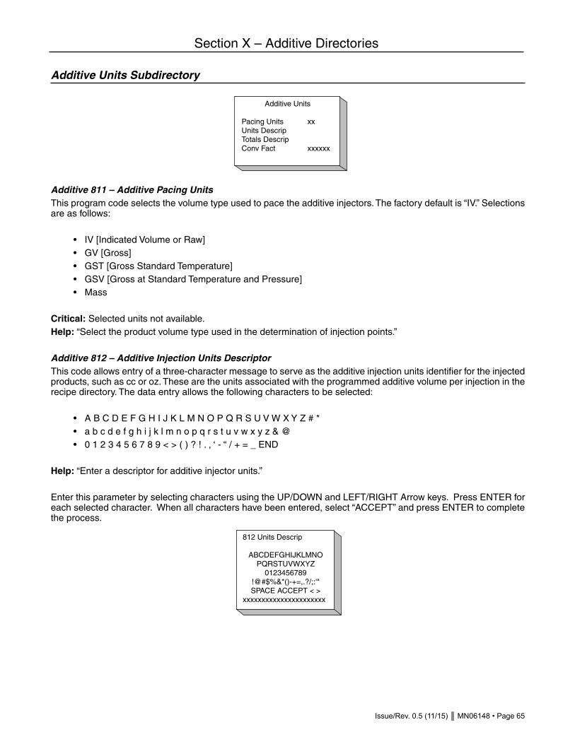
Issue/Rev. 0.5 (11/15) MN06148 • Page 65
Section X – Additive Directories
Additive Units Subdirectory
Additive 811 – Additive Pacing UnitsThis program code selects the volume type used to pace the additive injectors. The factory default is “IV.” Selections are as follows: • IV [Indicated Volume or Raw] • GV [Gross] • GST [Gross Standard Temperature] • GSV [Gross at Standard Temperature and Pressure] • Mass
Critical: Selected units not available.Help: “Select the product volume type used in the determination of injection points.”
Additive 812 – Additive Injection Units DescriptorThis code allows entry of a three-character message to serve as the additive injection units identifier for the injected products, such as cc or oz. These are the units associated with the programmed additive volume per injection in the recipe directory. The data entry allows the following characters to be selected: • A B C D E F G H I J K L M N O P Q R S U V W X Y Z # * • a b c d e f g h i j k l m n o p q r s t u v w x y z & @ • 0 1 2 3 4 5 6 7 8 9 < > ( ) ? ! . , ‘ - “ / + = _ END
Help: “Enter a descriptor for additive injector units.”
Enter this parameter by selecting characters using the UP/DOWN and LEFT/RIGHT Arrow keys. Press ENTER for each selected character. When all characters have been entered, select “ACCEPT” and press ENTER to complete the process.
Additive Units
Pacing Units xxUnits DescripTotals DescripConv Fact xxxxxx
812 Units Descrip
ABCDEFGHIJKLMNO PQRSTUVWXYZ
0123456789 !@#$%&*()-+=,.?/;:'"SPACE ACCEPT < >
xxxxxxxxxxxxxxxxxxxxxx

Page 66 • MN06148 Issue/Rev. 0.5 (11/15)
Section X – Additive Directories
Additive 813 – Additive Totals Units DescriptorThis program code is a 3-character text entry used to define the units in which additive injector volumes are totaled. All additive injector totals available in dynamic displays and via communications will be in these units. The data entry allows the following characters to be selected: • A B C D E F G H I J K L M N O P Q R S U V W X Y Z # * • a b c d e f g h i j k l m n o p q r s t u v w x y z & @ • 0 1 2 3 4 5 6 7 8 9 < > ( ) ? ! . , ‘ - “ / + = _ END
Help: “Enter a descriptor for additive totals units.”Enter this parameter by selecting characters using the UP/DOWN and LEFT/RIGHT Arrow keys. Press ENTER for each selected character. When all characters have been entered, select “ACCEPT” and press ENTER to complete the process.
Additive 814 – Injection/Totalization Conversion FactorThis ten-digit numeric entry is used to convert injection units to totals units. This parameter is an exponential entry, with a range of 0 to 9.999999e+09. The microLoad.net uses this formula for the conversion:Volume in Injector units / Conversion factor = Volume in Total UnitsExample: If injection units are in cc., and injector totals are to be displayed in liters, the value would be 1000. (1.00 e+03).
Help: “Enter the number of injection units in each add totals unit (e.g., number of cc’s per gallon).”
813 Totals Descrip
ABCDEFGHIJKLMNO PQRSTUVWXYZ
0123456789 !@#$%&*()-+=,.?/;:'"SPACE ACCEPT < >
xxxxxxxxxxxxxxxxxxxxxx

Issue/Rev. 0.5 (11/15) MN06148 • Page 67
Section X – Additive Directories
Injector Control Subdirectory
Additive 821 – Additive Stop OptionThis parameter defines when the additive injection will stop for each batch. It also determines whether the rate will be recalculated so that the total amount of additive expected for the preset volume will be delivered before the downcounter reaches the volume in Additive 822 – Additive Stop Volume. The factory default is “Batch.” Selections are as follows: • End of Batch – Stop volume is ignored. Additive is delivered until end of batch. • No recalculation – Additive is delivered as above but injection halts when only stop volume remains. • Recalculation – Proper additive volume for entire preset volume is “squeezed” so that the correct additive amount for preset is delivered when the stop volume is reached.Help: “Injections may stop at the end of a batch or at the additive stop volume with or without recalculation of the inject rate.”
Additive 822 – Additive Stop VolumeThis three-digit entry allows the operator to select the amount of product remaining to be delivered when the additive injectors will be shut down. This code is used only in conjunction with Injector Option 1 and 2 of parameter Additive 821. The range of this code is 0 to 999.Help: “Enter the preset amount left to be delivered before injector shutdown (in preset volume type).”
Additive 823 – Additive Clean Line AlarmThis three-digit numeric entry determines the tolerance for the additive stop volume. If the batch is ended before the programmed stop volume has been completely delivered, this entry determines if an alarm will occur. An alarm will occur at batch end if the volume delivered since the last injection is short of the stop volume by more than this entry. The range of the entry is 0 to 999. An entry of 0 disables the alarm.Help: “Set the tolerance allowed for under-run of additive stop volume. Zero disables additive clean line alarm.”
Additive 824 – Piston Injector Feedback ErrorsThis one-digit numeric entry is used with piston injectors with feedback only. It defines the number of missed feedback signals that can occur before an additive feedback alarm occurs. The range is 0 to 9.Help: “Enter the maximum number of feedback errors allowed for a piston injector before alarming.”
Additive 825 – Piston Stop ActionThis parameter determines whether any active piston injector outputs are de-energized if the batch is stopped prematurely due to the stop key, an alarm, or loss of permissive. This does not affect the state of the piston injector solenoid output at batch end or transaction end. Selections are as follows: • No Action • De-energizeHelp: “De-energize piston injector output when batch is stopped, alarm occurs, or on loss of permissive.”
Injector Control
Stop Option xxxxxxStop Amount xClean Line Add xPiston Stop xxxxx

Page 68 • MN06148 Issue/Rev. 0.5 (11/15)
Section X – Additive Directories
Metered Injector Subdirectory
Additive 831 – Metered Injector K FactorThis seven-digit code defines the nominal number of pulses from a meter for one unit of registration. The value must be between 0.001 and 9999.999.Critical: Entry must not be zero.Critical: Metered injector pulse input not configured.Note: No-entry if additive injector type is not metered injector.Help: “Enter the K factor in pulses per unit volume for the metered injector.”
Additive 832 – Metered Injector Meter FactorThe meter factor for the additive meters that are being controlled directly by the microLoad.net are programmed in these parameters. If the additives are being controlled through communications and ancillary equipment, no value should be programmed in these parameters. The range of these entries is 0.0000 to 9.9999. Meter factor equals the actual volume times the current meter factor times the K factor, all divided by the input pulses. The factory default is “0.0000”.Critical: Entry must not be zeroHelp: “Enter the meter factor for the metered injector.”
Additive 833 – Metered Injector High ToleranceThese four-digit numeric entries define a percentage in three whole digits, followed by one decimal place, for the amount the actual injected volume can surpass the average volume required to meet the additive needs. The range of this entry is 0 to 999.9. The factory default is “0”.Help: “Enter the % above the averaged amount before an error is counted.”
Additive 834 – Metered Injector Low ToleranceThese four-digit numeric entries define a percentage in three whole digits, followed by one decimal place, for the amount the actual injected volume can be under the average volume required to meet the additive needs. The range of this entry is 0 to 999.9. The factory default is “0”.Help: “Enter the % below the averaged amount before an error is counted.”
Additive 835 – Metered Injector Maximum Tolerance ErrorThese two-digit numeric entries allow the operator to set up how many times during the batch that the high and low tolerance percentages can be exceeded continuously before an alarm is set. The range of this entry is from 0 to 99. The factory default is “0”.Help: “Enter the maximum number of tolerance errors allowed before an alarm is set.”
Metered Inj Menu
K-Fact xxxxxMtr-Fact xxxxxHigh Tol xxLow Tol xxMax Tol Err x

Issue/Rev. 0.5 (11/15) MN06148 • Page 69
Section X – Additive Directories
Smart Injector Subdirectory
Additive 841 to 844 – Smart Injector #1, #2, #3, #4 AddressThis three-digit numeric entry is used with any smart injector type. It defines the communications address for the associated injector. When more than one injector is installed at microLoad.net, injector addresses must be unique. The range of this program code is 0 to 999.Critical: Injector address must be unique.Note: No entry if corresponding type is not a Smart Injector (Titan, Blend-Pak types).Help: “Enter the communications address for this smart injector.”
Smart Inj Menu
Inj #1 Address xInj #2 Address xInj #3 Address xInj #4 Address x

Page 70 • MN06148 Issue/Rev. 0.5 (11/15)
Section XI – Recipe Directories
Recipe Directory
The Recipe Directory provides the operator with two methods of accessing the recipes for setup. The recipe desired may be accessed by enter the recipe # or by picking the recipe from a list.
Recipe Setup Subdirectory
The Recipe Setup Subdirectory provides a means to establish recipe identification parameters i.e. Recipe number and name.
Recipe xx
Recipe Used xxxRecipe Name xxxx
XX Recipe UsedYes
No Yes
PRINT=Help
xx Recipe Name
ABCDEFGHIJKLMNO PQRSTUVWXYZ
0123456789 !@#$%&*()-+=,.?/;:'"SPACE ACCEPT < >
xxxxxxxxxxxxxxxxxxxxxx
Recipe Dir
Enter Recipe # xx
Recipe Dir
Enter Recipe #Select Recipe
Recipe Dir
Recipe 1 xxxxxRecipe 2 xxxxxRecipe 3Recipe 4Recipe 5Recipe 6Recipe 7Recipe 8Recipe 9Recipe 10Recipe 11Recipe 12
more...
Recipe xx
Recipe SetupRecipe Injectors

Issue/Rev. 0.5 (11/15) MN06148 • Page 71
Section XI – Recipe Directories
Recipe rr01 – Recipe Used (rr = Recipe# 01-12)This program code indicates whether a recipe is configured for use. Selections are as follows: • No • Yes
Critical: At least one recipe must be configured.Help: “Select whether this recipe is to be enabled for use or not.”
Recipe rr02 – Recipe Name (rr = Recipe# 01-12)This program code allows an alphanumeric entry of up to fifteen (15) characters. It is used as an identifier of the recipe in the preset display and on the product receipt ticket. The data entry allows the following characters to be selected as part of the name: • A B C D E F G H I J K L M N O P Q R S U V W X Y Z # * • a b c d e f g h i j k l m n o p q r s t u v w x y z & @ • 0 1 2 3 4 5 6 7 8 9 < > ( ) ? ! . , ‘ - “ / + = _ END
Enter this parameter by selecting characters using the UP/DOWN and LEFT/RIGHT Arrow keys. Press ENTER for each selected character. When all characters have been entered, select “ACCEPT” and press ENTER to complete the process. Help: “Enter an alphanumeric message to identify this recipe.”
Recipe Injectors Subdirectory
Parameters in this subdirectory establish the values for injector volume and rate for a given recipe.
Recipe rr11, rr13, rr15, rr17 – Injector Volume (rr = Recipe# 00-12)These six-digit numeric codes define the volume of additive product that will be injected for each cycle of additive injector (e.g., an entry of 000.100 shows that one-tenth of a unit of additive will be injected each cycle of the injector). The range of this program code is 0.000 to 999.999.For piston or metered injectors, the units for this additive volume are as programmed in system code 881. For smart injectors, this is the number downloaded to the smart injector. The units may be fixed or programmed on the smart injector.When using a Smart Additive Injector System the additive injector volume is downloaded to the additive injector at the start of each batch.Help: “Enter the Additive volume delivered per injection cycle.”
Recipe xxInj #1 Vol xxxxxInj #1 Rate xxxInj #2 Vol xxxxxInj #2 Rate xxxInj #3 Vol xxxxxInj #3 Rate xxxInj #4 Vol xxxxxInj #4 Rate xxx

Page 72 • MN06148 Issue/Rev. 0.5 (11/15)
Section XI – Recipe Directories
Some additive injectors do not support the full range that we have offered here. Titan injectors accept only whole numbers for the volume. Gate City injectors (Blend-Pak, and Mini-Pak) accept injector volume in tenths. The microLoad.net will truncate the entry to the format required for the smart injector.
Code Functionrr11 Injector 1 Volumerr13 Injector 2 Volumerr15 Injector 3 Volumerr17 Injector 4 VolumeNote: No entry if associated injector not configured to arm.Help: “Enter the additive volume delivered per injection cycle.”
Recipe rr12, rr14, rr16, rr18 – Injector Rate (rr = Recipe# 00-12)This parameter is used to define the rate at which additive is injected into the product stream during delivery. This is the volume of product per additive injection, typically 40 gallons or 100 liters. The range of this three-digit number entry is 0 to 999 volume units.If the injector is a flow controlled injector, the value represents a percentage of the preset amount that this additive will comprise. For example, with a preset of 1000 units and this parameter programmed to 10.0, the result will be 900 units of the component products in the recipe plus 100 units of this additive. The range is 0 to 10.0 percent.
Code Functionrr12 Injector 1 Raterr14 Injector 2 Raterr16 Injector 3 Raterr18 Injector 4 RateNote: No entry if associated injector not configured.Help: “Enter the additive injector rate, in product volume per injection.”

Issue/Rev. 0.5 (11/15) MN06148 • Page 73
Program Mode Diagnostics
The Program Mode Diagnostics are used to troubleshoot or to determine the current status of the microLoad. Program Mode Diagnostics is selected by moving the cursor to “Diagnostics” on the Program Mode menu and pressing ENTER. This will display the Diagnostics menu. Note that Program Mode Diagnostics are only available if Program Mode was entered at a security level at or greater than the level entered in General Purpose Parameter 165.
To access the Diagnostics Directory, arrow up or down until the arrow is beside the Diagnostics Menu.
Pressing ENTER with the arrow in front of Diagnostics will display six items of the Diagnostics Menu. Pressing the up and/or down arrows will step through the Diagnostics Menu. The available diagnostics in the order that they ap-pear on the menu are as follows: • Analog Input Test • Digital Input Test • Digital Output Test • Pulse Input Test • Pulse Output Test • Prove Metered Injector Additives • Communications Test • Keypad Test • Display Pixel Test • Boolean/Algebraic • Reset Totals • Reset Intervals • Reset Dual Pulse Errors • Erase Event Log • Erase Transaction Log • Erase Web Pages • Card Reader Database Update • Mass Meter Menu • Upgrade Firmware • Factory Initialize • Factory Diagnostics • Watchdog Reset Test • Power-up Diagnostics • Flow Stimulator • Field Test Initialize
Section XII – Diagnostic Directories
Program Mode Menu
Configuration DirGen Purpose DirFlow Control DirVol Accuracy DirTemp/Dens DirPressure Dir
more...
Program Mode Menu
Alarm Dir Communications Dir Additive Inj Dir Recipe Dir- > Diagnostics Exit Without Saving
more...

Page 74 • MN06148 Issue/Rev. 0.5 (11/15)
Analog Input TestSelecting Analog Input Test and pressing ENTER will display the status of the analog input points in the microLoad.
Digital Input TestSelecting Digital Input Test and pressing ENTER will display the status of the digital input points in the microLoad.
This screen shows the input number, the function that is programmed in the unit for the input and the status of the input point (i.e., if it is on (closed) or off (open)). Check the inputs by changing the status of the input, then referring to the diagnostic screen to see if the microLoad.net recognizes the change of state.
Digital Output TestSelect “Digital Output Test” and press ENTER to display the status of the digital output points in the microLoad.
Moving the arrow to the output that is to be tested and pressing ENTER will change the state of the output. An ex-ample would be moving the arrow to output #2 Pump and pressing ENTER.
Section XII – Diagnostic Directories
Digital Output Test
#1 NA OFF - > #2 Pump OFF #3 Upstream Solenoid OFF #4 Downstream Solenoid OFF #5 NA OFF #6 NA OFF
Digital Output Test
#1 NA OFF#2 Pump OFF#3 Upstream Solenoid OFF#4 Downstream Solenoid OFF#5 NA OFF#6 NA OFF
Analog Inputs
#1: A1 Temp In 76.6 F 109.657 Ohms 28744 #2: A1 Pressure 210.0 Psi 14.023 mA 36753
#1Cal: 013072 0917504#2Cal: 013072 0917504
Digital Inputs
#1 Permissive 1 ON#2 Permissive 2 ON#3 Block Valve Fdbk OFF
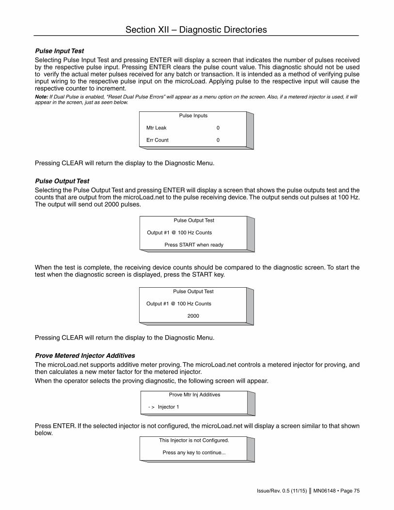
Issue/Rev. 0.5 (11/15) MN06148 • Page 75
Pulse Input TestSelecting Pulse Input Test and pressing ENTER will display a screen that indicates the number of pulses received by the respective pulse input. Pressing ENTER clears the pulse count value. This diagnostic should not be used to verify the actual meter pulses received for any batch or transaction. It is intended as a method of verifying pulse input wiring to the respective pulse input on the microLoad. Applying pulse to the respective input will cause the respective counter to increment.Note: If Dual Pulse is enabled, "Reset Dual Pulse Errors” will appear as a menu option on the screen. Also, if a metered injector is used, it will appear in the screen, just as seen below.
Pressing CLEAR will return the display to the Diagnostic Menu.
Pulse Output TestSelecting the Pulse Output Test and pressing ENTER will display a screen that shows the pulse outputs test and the counts that are output from the microLoad.net to the pulse receiving device. The output sends out pulses at 100 Hz. The output will send out 2000 pulses.
When the test is complete, the receiving device counts should be compared to the diagnostic screen. To start the test when the diagnostic screen is displayed, press the START key.
Pressing CLEAR will return the display to the Diagnostic Menu.
Prove Metered Injector AdditivesThe microLoad.net supports additive meter proving. The microLoad.net controls a metered injector for proving, and then calculates a new meter factor for the metered injector.When the operator selects the proving diagnostic, the following screen will appear.
Press ENTER. If the selected injector is not configured, the microLoad.net will display a screen similar to that shown below.
Section XII – Diagnostic Directories
Prove Mtr Inj Additives
- > Injector 1
This Injector is not Configured.
Press any key to continue...
Pulse Output Test
Output #1 @ 100 Hz Counts
2000
Pulse Inputs
Mtr Leak 0
Err Count 0
Pulse Output Test
Output #1 @ 100 Hz Counts
Press START when ready

Page 76 • MN06148 Issue/Rev. 0.5 (11/15)
If the injector is configured for operation, the microLoad.net will display a screen similar to that shown below.
A description of each of the entries is a follows:
Amount (Amt)This is an input field for the user to specify the volume of additive to be attempted for each test injection. The volume is displayed in the units specified in Additive Directory 812 (Injector Units).
Injector Is:Press ENTER to authorize the injector; this will also energize the additive pump output.
InjectThis selection initiates an injection. If an injection is already in progress, this selection is ignored. Once the test in-jection is complete, the selection accepts additional input. This operation is not permitted if the injector is incorrectly programmed. The test injection volume must be valid and the injection must be authorized.
Injection NumberThis display-only item is a count of the number of test injections performed on this metered injector for this current diagnostic.
CountsThis display-only item is a count of the number of pulses received by the metered injector, starting from when the diagnostic first began. This selection is zeroed when the this screen is first entered.
VolumeThis display-only item is the current amount of additive as calculated from the parameters programmed for the me-tered injector and the current number of pulses. The count is displayed in units of totalized additive.When the test injections are complete, press CLEAR. The microLoad.net will display a screen similar to that shown below. Enter the actual amount of additive as measured by an external device (e.g., a graduated cylinder). Select the volume units in which the total is to be displayed. If no test injections have been performed, or if there are no recorded additive pulses or volumes, the CLEAR key will exit the diagnostic altogether.
An asterisk (*) marks the currently selected volume type in which the actual volume units will be entered. One of these selected is always indicated. The actual volume injected is also entered on this screen. When this amount is entered, moving the selection to “Continue” allows the calculation process to proceed. Pressing CLEAR exits this diagnostic.Once the “Continue” option has been selected, the microLoad.net will calculate a new meter factor based on the
Section XII – Diagnostic Directories
Enter Actual Additive Amount
Injected Units (*) uuu Totalized Units (*) uuu Additive Volume 12345678.123- > Continue
Prove Additive #1
- > Amt 1234.123 gal Injector is Authorized Inject Inj #4
Counts 123456
Vol 12345678.123

Issue/Rev. 0.5 (11/15) MN06148 • Page 77
volume entered. This new meter factor, the current meter factor, and the choice of accepting this meter factor, are presented on the next screen, as shown on the next page.
Rejecting the new meter factor exits the diagnostic and erases all proving data. Accepting the new meter factor stores it in the database. Saving the factor in non-volatile memory requires a program mode exit with changes. If the new meter is accepted but the unit loses power before exiting program mode, the new meter factor is lost.
Communications TestSelecting “Communications Test” from the menu allows the operator to run a diagnostic on any of the communication ports on the microLoad. Pressing ENTER with the cursor in front of selection one will activate a popup screen where the operator can select the communications port to be tested.
For this test to be completed, the transmit and receive terminals on the comm port must be connected. Once the comm port has been selected by moving the arrow to the required port, pressing ENTER will start the communications test.
The test will display the characters that are being transmitted on the transmit line. It will also display the characters as they are received back into the instrument. Also displayed are the errors that have occurred during the test, the overruns, the parity, and the framing errors. Pressing CLEAR will end the test and return the unit to the Communica-tions Test menu. The test is identical for the three ports. The only difference in the display will be the communications part number and the channel designation.
Keypad TestSelect “Keypad Test” from the menu to run a diagnostic test on the keypad of the microLoad. Pressing ENTER will display the keypad test screen.
Section XII – Diagnostic Directories
Keypad Test
Press any key and it will bedisplayed. Press CLEAR twice
to exit.
Comm Port 1 Test
Tx SRxErrs :00003Overruns :00000Parity :00000Framing :00000
Press CLEAR to stop
New Additive Meter Factor
New M-Factor: 1.12345 % Diff Old M-Factor: 1.12345 123.45% - > Accept New Meter Factor Reject New Meter Factor
Select comm port to
- > Comm 1 Comm 2 Comm 3

Page 78 • MN06148 Issue/Rev. 0.5 (11/15)
With this screen displayed, any key that is pressed will appear on the screen as the key that was pressed.
Display Pixel TestSelecting “Display Pixel Test” and pressing ENTER will initiate the pixel test on the display. All the pixels will be lit, allowing the operator to determine if any of the pixels on the display are not functioning. Pressing CLEAR will termi-nate the test and return the unit to the Diagnostic menu.
Boolean/Algebraic ProcessingSelecting “Boolean/Algebraic Processing” and pressing ENTER will display the following list of Boolean/Algebraic-related diagnostic displays that can be viewed by the operator. • User Boolean Registers • User Algebraic Registers • Equation Line State • General Purpose Timers
User Boolean RegistersSelecting “User Boolean Registers” and pressing ENTER will display the first twelve user Boolean registers. There are a total of 50 user Boolean registers. The range of these registers is 0 to 255. These registers are set aside for the user. They can be written to by Boolean/Algebraic equations or via communications. The values can be printed on user-defined reports.
User Algebraic RegistersSelecting “User Algebraic Registers” and pressing ENTER will display the first six user algebraic registers. There are a total of 50 user Algebraic registers.
Section XII – Diagnostic Directories
User Boolean Regs
#1 0 #7 0#2 0 #8 0#3 0 #9 0#4 0 #10 0#5 0 #11 0#6 0 #12 0
More...
User Algebraic Regs
#1 0 #2 0 #3 0 #4 0 #5 0 #6 0
More...
Keypad Test
STOP
Press any key and it will be displayed. Press CLEAR twice
to exit.

Issue/Rev. 0.5 (11/15) MN06148 • Page 79
Equation Line StateThe Equation Line Status displays the current status of the equations, where “D” indicates that the equation is dis-abled, “T” is True, and “F” is False. All equations without an “IF” statement will have a “True” status. Those with an “IF” will indicate the result of the “IF” expression: either “True” or “False.” There are a total of 50 lines.
Entering the equation number that is to be disabled and pressing ENTER will change the status on the screen from either “T” (True) or “F” (False) to “D” (Disabled). The equation from that point until enabled will not be active. To enable an equation the same process is followed, except that the screen will indicate that the equation is “D” (Disabled). Entering the equation number will enable that equation.
General Purpose TimersSelecting “General Purpose Timers” and pressing ENTER will display nine of the sixteen general purpose timers that can be activated and used through the Boolean and/or algebraic equations.
The timers are incremented at these intervals:
The operator can clear the times by writing a zero to the database location of the desired timer. Like the user Bool-ean and user algebraic registers, these timers are reserved strictly for the user. They may be started via Boolean/Algebraic equations or via communications. Timers are very useful in the design of equations as they allow setting a user alarm or taking some other action after an event has persisted for a period of time.
Section XII – Diagnostic Directories
General Purpose Timers
#1 0 #7 0#2 0 #8 0#3 0 #4 0#5 0#6 0
Timer Numbers Resolution Range
1 - 2 0.1 second 109 minutes3 - 4 1.0 second 18.2 hours5 - 6 1.0 minute 45.5 days7 - 8 1 hour 7.5 years
Toggle ON/OFF
Enter Equation # - > 1
Equation Line State
1. 7. 2. 8. 3. 9. 4. 10. 5. 11. 6. 12.
More... STOP to toggle

Page 80 • MN06148 Issue/Rev. 0.5 (11/15)
Reset TotalsThis diagnostic is used for resetting the non-resettable totals. Pressing ENTER will display the following screen.
Pressing CLEAR will return the unit to the Diagnostics Menu screen. Pressing ENTER on the screen will reset the non-resettable totals (both product and additive) and return the unit to the Diagnostics Menu Screen.
Reset Intervals
This diagnostic is used to reset all of the interval totals (hourly / daily / weekly / monthy).
Reset Dual PulseThis diagnostic is used for resetting the dual pulse errors if they occur outside of the options programmed in meter code 305 “Dual Pulse Error Reset”. For instance if code 305 is programmed for no automatic reset of the errors this diagnostic would have to be used for resetting the errors if they exceeded the count programmed in meter code 304 “Dual Pulse Error Count”.To reset the errors, scroll through the menu until the cursor is in front of “Reset Dual Pulse Errors” and press ENTER. The following screen will appear:
Erase Event LogThis diagnostic is used for erasing the event log. Pressing ENTER will display the following screen:
Pressing CLEAR will return the unit to the Diagnostics Menu screen without erasing the event log. Pressing ENTER will erase the event log and return the unit to the Diagnostics Menu screen.
Erase Transaction LogThis diagnostic is used to erase the transaction log. Pressing ENTER with the arrow in front of “Erase Transaction Log” will display the following screen.
Section XII – Diagnostic Directories
Erase Event LogWARNING
The event log will beerased! Press ENTERto continue to CLEAR
to exit.
Erase Trans LogWARNING
The transaction logwill be erased! PressENTER to continue
CLEAR to exit.
Reset Dual Pulse ErrorsWARNING
Dual Pulse Error counter will be reset.Press ENTER to continue or
CLEAR to exit.
Reset TotalsWARNING
Non-resettablevolumes will be
reset. Press ENTER tocontinue or CLEAR to
exit.
Reset TotalsWARNING
Interval totals will be reset. Press ENTER to continue or CLEAR to exit.

Issue/Rev. 0.5 (11/15) MN06148 • Page 81
Pressing CLEAR will return the unit to the Diagnostics Menu screen without erasing the transaction log. Pressing ENTER will erase the transaction log and return the unit to the Diagnostics Menu. Not only will the log be erased, but historic transactions currently archived will no longer be available via communications.
Erase Web PagesThis diagnostic is used to erase the web pages. Pressing ENTER with the arrow in front of “Erase Transaction Log” will display the following screen:
Pressing CLEAR will return the unit to the Diagnostics Menu screen without erasing the web pages. Pressing ENTER will erase the web pages and return the unit to the Diagnostics Menu.
Card Reader Database UpdateSelecting “Card Reader Database Update” and pressing ENTER will display a screen that prompts the operator to add a new entry to the card reader of driver IDs. Once the data has been successfully entered, this diagnostic con-firms that the card has been read and recorded. Press ENTER to add another card or CLEAR to exit the diagnostic.
Mass Meter MenuSelecting “Mass Meter Menu” from Program Mode Diagnostics displays the opening mass meter diagnostics screen. Mass meter diagnostics display mass meter information and allow the operator to perform certain maintenance tasks. These diagnostics are only available when a mass meter has been configured for use.
Press ENTER and the following display will then appear:
Revision and DateSelecting “Revision and Date” from the Mass Meter Diagnostics menu displays a screen similar to that shown below. This option indicates the software version and date associated with the mass meter.
Magnitude and DriveSelecting “Magnitude and Drive” from the Mass Meter Diagnostics menu displays a screen similar to that shown below:
Section XII – Diagnostic Directories
- > Revision and Date Magnitude and Drive Zero Tare
Revision 14Date 10/03
- > Drive XXXX Forward Magnitude XXXX Reverse Magnitude XXXX
Card-in new card
CLEAR to cancel.
Erase Web PagesWARNING
All web pages will beerased! Press ENTERto continue or CLEAR
to exit.

Page 82 • MN06148 Issue/Rev. 0.5 (11/15)
This screen displays the current valves and is dynamically updated. Press CLEAR to return to the Mass Meter Diagnostics menu.
ZeroSelecting “Zero” from the Mass Meter Diagnostics menu displays a screen similar to that shown below:
Position the cursor beside “Yes” and press ENTER to set the meter to zero. The screen will then display “Zeroing in Progress” until the process is complete. Once the meter has been set back to zero, the message will change to “Zeroing Complete – Press Clear to Exit.” Note that there can be no flow in progress when “Zero” is initiated.Position the cursor beside “No” and press ENTER to abort the zero function and return the display to the Mass Meter Diagnostics menu.
TareSelecting “Tare” from the Mass Meter Diagnostics menu displays a screen similar to that shown below.
This screen allows the operator to specify a new tare value for a mass meter. Use the keypad to indicate the new tare value and then press ENTER. The display will return to the Mass Meter Diagnostics menu.
Upgrade FirmwareThis diagnostic tool will allow a new software revision to be downloaded into the microLoad. In order for a new soft-ware revision to be downloaded the Comlink Level must be set to the highest level, unless, the microLoad.net is in the diagnostic screen shown below, which will override the Comlink Level setting.
Factory InitializeSelecting “Factory Initialize” and pressing ENTER will display a screen that tells the operator that if ENTER is pressed, all the parameters in the unit will be reset to the default values as they were shipped from the factory. Caution: Running this diagnostic will change all parameters that have been programmed previously. The only data saved will be that which is stored in the audit trail for Weights and Measures Approvals.
Factory DiagnosticsThe Watchdog Rest Test, Powerup Diagnostics, Flow Simulator, and Field Test Init are for factory use only.
Section XII – Diagnostic Directories
Current Tare XXX New Tare - > XXX
Upgrade Firmware
Waiting for newfirmware revision
Press CLEAR to Cancel
Factory InitializeWARNING
All run data andParameters will be
erased! Press ENTERto continue or CLEAR
to exit.
Are You Sure? - > Yes No

Issue/Rev. 0.5 (11/15) MN06148 • Page 83
Section XIII – Appendix
Appendix I – Alarms
Table of Equivalent Error Codes
Blend-Pak Injector – From the Blend-Pak’s Point of View
microLoad.net Equivalent Error Code
Excess Additive RA: Additive Frequency Alarm
No Additive Flow NA: No Additive Pulses Alarm
No Fuel Flow GA: Additive Injector Error
Low Additive KA: Low Additive Volume
Leaking Solenoid MA: Excess Additive Pulses
No Act. Time-Out GA: Additive Injector Error
Fuel Flow Switch Failure GA: Additive Injector Error
Low Flow Switch Failure GA: Additive Injector Error
Flash Vol Alarm GA: Additive Injector Error
Mini-Pak Injector – From the Mini-Pak Point of View
microLoad.net Equivalent Error Code
Additive Cycle Volume Alarm GA: Additive Injector Error
No Additive Alarm NA: No Additive Pulses Alarm
Leaking Solenoid MA: Excess Additive Pulses
Firmware Failure GA: Additive Injector Error
EEPROM Failure GA: Additive Injector Error
Metered Injector – If this happens... microLoad.net – This alarm occurs...
Injections are occurring too fast OR: Overspeed Metered Injector
No additive pulses are registering NA: No Additive Pulses Alarm
Out of tolerance high RA: Additive Frequency Alarm
Out of tolerance low KA: Low Additive Volume
Titan Injector – From the Titan’s Point of View
microLoad.net Equivalent Error Code
Alarm Low 1 RA: Additive Frequency Alarm
Alarm Low 2 KA: Low Additive Volume
Pulse Detection NA: No Additive Pulses Alarm
Alarm High MA: Excess Additive Pulses
Product Pulse Failure GA: Additive Injector Error
Unclean Product GA: Additive Injector Error
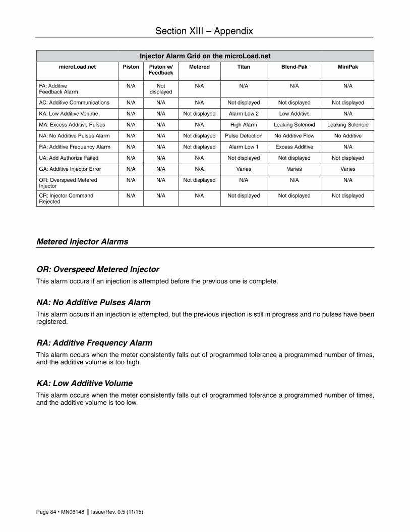
Page 84 • MN06148 Issue/Rev. 0.5 (11/15)
Section XIII – Appendix
Injector Alarm Grid on the microLoad.net
microLoad.net Piston Piston w/ Feedback
Metered Titan Blend-Pak MiniPak
FA: Additive Feedback Alarm
N/A Not displayed
N/A N/A N/A N/A
AC: Additive Communications N/A N/A N/A Not displayed Not displayed Not displayed
KA: Low Additive Volume N/A N/A Not displayed Alarm Low 2 Low Additive N/A
MA: Excess Additive Pulses N/A N/A N/A High Alarm Leaking Solenoid Leaking Solenoid
NA: No Additive Pulses Alarm N/A N/A Not displayed Pulse Detection No Additive Flow No Additive
RA: Additive Frequency Alarm N/A N/A Not displayed Alarm Low 1 Excess Additive N/A
UA: Add Authorize Failed N/A N/A N/A Not displayed Not displayed Not displayed
GA: Additive Injector Error N/A N/A N/A Varies Varies Varies
OR: Overspeed Metered Injector
N/A N/A Not displayed N/A N/A N/A
CR: Injector Command Rejected
N/A N/A N/A Not displayed Not displayed Not displayed
Metered Injector Alarms
OR: Overspeed Metered InjectorThis alarm occurs if an injection is attempted before the previous one is complete.
NA: No Additive Pulses AlarmThis alarm occurs if an injection is attempted, but the previous injection is still in progress and no pulses have been registered.
RA: Additive Frequency AlarmThis alarm occurs when the meter consistently falls out of programmed tolerance a programmed number of times, and the additive volume is too high.
KA: Low Additive VolumeThis alarm occurs when the meter consistently falls out of programmed tolerance a programmed number of times, and the additive volume is too low.
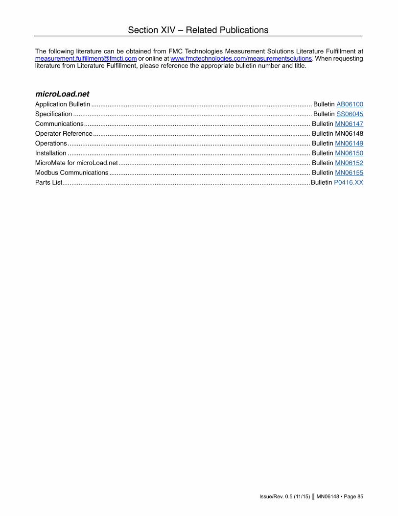
Issue/Rev. 0.5 (11/15) MN06148 • Page 85
Section XIV – Related Publications
The following literature can be obtained from FMC Technologies Measurement Solutions Literature Fulfillment at [email protected] or online at www.fmctechnologies.com/measurementsolutions. When requesting literature from Literature Fulfillment, please reference the appropriate bulletin number and title.
microLoad.netApplication Bulletin .......................................................................................................................... Bulletin AB06100
Specification .................................................................................................................................... Bulletin SS06045
Communications ............................................................................................................................. Bulletin MN06147
Operator Reference ........................................................................................................................ Bulletin MN06148
Operations ...................................................................................................................................... Bulletin MN06149
Installation ...................................................................................................................................... Bulletin MN06150
MicroMate for microLoad.net .......................................................................................................... Bulletin MN06152
Modbus Communications ............................................................................................................... Bulletin MN06155
Parts List .........................................................................................................................................Bulletin P0416.XX

Revisions included in MN06148 Issue/Rev. 0.5 (11/15):
Total Revision.
The specifications contained herein are subject to change without notice and any user of said specifications should verify from the manufacturer that the specifications are currently in effect. Otherwise, the manufacturer assumes no responsibility for the use of specifications which may have been changed and are no longer in effect.
Contact information is subject to change. For the most current contact information, visit our website at www.fmctechnologies.com/measurementsolutions and click on the “Contact Us” link in the left-hand column.
www.fmctechnologies.com/measurementsolutions
© 2015 FMC Technologies. All rights reserved. MN06148 Issue/Rev. 0.5 (11/15)
FMC Technologies Measurement Solutions, Inc.500 North Sam Houston Parkway West,Suite 100Houston, Texas 77067 USAP:+1 281.260.2190
USA Operation 1602 Wagner AvenueErie, Pennsylvania 16510 USAP:+1 814.898.5000
Germany Operation Smith Meter GmbHRegentstrasse 125474 Ellerbek, GermanyP:+49 4101 304.0