ELECTRONIC METAL LOCATORS - tinaja.com · frn111 a kw dollars 11p to sprl'ializcd tho11sand-dollar...
5
ELECTRONIC METAL LOCATORS Basic Types and Design Factors lforf' i.� a r11111/01c11 on 1Cl111(s arailalifo for th1• 11011-military llM'I'. Cmnparatin� dwr(l(:f1�ri.�tic.� a"'/ 1wrfonnmu·1! of tlw /wai- f /'1�1111 m wy. i w I 1wti011-bala11 ', 1111 d tnm .�mi ti cr-recei i·1· r t.' 'f ws. By DONALD E. LANCASTER T llI· :a<h·:1nci11g cl<'dro1iit· art has 111ade possihlt• a . Ill'\\' Jamil�· ol 1111d<'rgro1111d 111l'lal lol'ators. These hght- W<"ight. st·11siti\·e i11stru111ents are designed as non-in- d11strial 1wrt" tqws. ai111l'd mai11ly at the 111i11eral pros- pl'dor. the hcad1L"o11il)('r. and the treasure l11111tcr. Toda\' the outdoor ath-e11t11rer has a L"hoice of fifty differe11t i11- stru111(•11ts a\·;tilahl<' from a doz(,ll firms, \'a; ·1·ing in price f111 a kw dollars 11p to sprl'ializcd tho11sand-dollar u11der- \\'at<·r 111od('ls. witl1 many \ ' t'rsions doubling as dl ' t•di\'l' pipe and l111rit>d wire lol'ators. Industrial models OtH'rate 011 the sa11H' hasic pri11L'iples. Altho11gh Llwre arc se\·f'ral hasic ddedor types. they all sl1arc se\'l'ral commo11 design principles. Obvious goals of a locator arc a high sensitivity to \'NY s111all ohjf'ds. drt'p pc11l'tratio11. a11d tl1e sharp disnimination of the ohjcd out- linl'. o basic del!'dor type l'an possibly meet ;ill tl1rce goals, si11cc each mnst emphasize 011e particular factor. Ba�ic Opcrati11 P.-inciple� All lectronic lol'ators ha\·e ;l transmitter used to illunii- natP a dl'sirl'd are:l and a second cirl'uit to interpret any cl11111gcs i11 that ill1m1ination caused by the pres1•11cl' of 111etal. Loop ;1nt<'1111as are oftl'n usl'CI to l'<>11ple the sig11als to a11d n the earth d11e to their small size and ex;1ctl1· predidalile field pat- tes. There are Sl'\'eral effects a nwtal tar- get will lt.l\·e if brought 11ear a loop a11- te1111a. First, the i11ducta11l'e of the loop will l'l1a11gc. H tl1e metal is iron, tl1" ii1d11l'la11c� will i11cr1·11s1', j11st ns an iron core i11crcases tlic i11d11cta11ce of a11 air- core l'oil. If tl1e nwtal is 11011-llla.g11dil'. it will 1il'cr1'11.,·1· tlw iml11da11l'e, just as a hrass corl' is ol't<·11 used to d1·ncast• the i11d11cta11c1· of all r. I t111 ii11g coil. St•t·1dly, th!' metal will ilistor/ tl1l' nor111;ilh· predictalill' field patte of tl1e a11te111w. This distorti1 111av tht·n lie Sl'llSl'd b\· elrdro11ic means . . Fi1 1 ally . ti ic metal will rel'l'ive tl1e tra11s111itted sig11al a11tl relnoadcast or rdl1·d it from . its 0\1'11 loc:iti1. j11st as a radar ill11111i11atcs a tar• . :t•t \\'l1icl1 i11 t11 r<'l>roadcasls or rdl!'l'lS t·11t·rg�· to December, 1966 Beat.frequency metal locator is shown here_ 1 The 111;1thl•111ati(·s IH'l1 i11d loop-;111tt·1111a opeti1 ren�als two l'l'lt'rg1· ten11s, a11 i11d11din· co11pli11g ten11 and a resis- tive l·o11pli11g term . Botl1 tcr111s e of equal importancl' one-sixth of a wavelc11gth away fron1 the loop. but for closl'r distances, the indndi\'l• tnm is mud1 stronger. This is thl' caSl' with practil'allv all electronil' lol'ators. and the design of a locator ma�· tl1en use snl'h i11dudive concepts as mu- tual i11d11da11l'C' and loosely co11pled transformers for n1atl1- e11wt ical analvsis. Thl' basil' . la\\'S behind intlucti\'c cu11pli11g dramatically illustrate wh�· metal lol'atio11 m·er any appreciable distance is a major dl,sign prohle111. ;tnd pai11fully show why tlH· perfor111a11t'l' of siplt: experill1e11t;il locator circ11its is oftt•11 high!�· disappointi11g. It t11s out th:1t ti)(' recei\·ed sig11al prodt1l'C'd hv an ind11cti\'!·ly (·ouplt·d target will nonnall)· IH' proportion;d to the c11/}(' of the target diameter and ill\·ersr- lv proportional to the sixtli po\\'er of tl1e target depth. ncg- ledillg the effects of terrestrial atten11atio11. A 011e-i11ch diam- eter target \\'ill produl'e 0111�· l/6-!tl1 tl1e signal of a similar f1r-int'l1-diaml'ter target at the sa1nc depth; a target fret dl'!'P \\'ill 01ily produce l /(itl1 tl1e rl'sponse of an idc'11tical one-foot-dt>ep target. Lt is possible to obtai11 deep 1wne- trat io11 Ii�· card11l cu11trol of the loop- a11te1111a field pattt>s, hut a drastic re- d11dio11 i11 small-object ddedaliility 11111st ii1t>vitahly accompa11y such a dc- s1g11. Opcratin� Fn�ri11e111·ic� Tl1c round-trip ill(l11L"tivc coupli11g lwt\\'!'l'll a target a11d an a11t!'1111a in air i11cr1•ases as tht> s111111re of the operating frf'q111·11cy. wliilf' tloe tern·strial ahsorp- tio11 heconws worst> as the s111111n· root of frl'q11e11l'Y · Cha11gi11g from an oper- ati11g frl'q111•11(·y of 10 kHz to one of I \lllz will i11cre;1st> tl1e receh·ed signal I>�· a factor of .000. hut tl1c terrestrial ahsorptio11 will si1111ilta11eously hccollll' t1•11 ti11ws wors<'. The highest possihk 01wrati11g frl'q111·11(·y that will still allow penl'tratio11 to the desired depth \\·ith- out l'X(·(·s�i\'e att1·1111atio11 should alwa\'s be 11sed. . Terrestrial attt•1111atio11 is l1ighlv d!'- pend(·nt upon tl1e resisli\·ity of the . earth 39 w.americanradiohistorv.com
Transcript of ELECTRONIC METAL LOCATORS - tinaja.com · frn111 a kw dollars 11p to sprl'ializcd tho11sand-dollar...

ELECTRONIC METAL LOCATORS Basic Types and Design Factors
lforf' i.� a r11111/01c11 on 1Cl111(s arailalifo for th1• 11011-military llM'I'. Cmnparatin� dwr(l(:f1�ri.�tic.� a"'/ 1wrfonnmu·1! of tlw /waif /'1�1111 m wy. i w I 1wti011-bala11 Cl', 1111 d tnm .�mi ti cr-recei i·1· r t.' 'f ws.
By DONALD E. LANCASTER
T llI·:a<h·:1nci11g cl<'dro1iit· art has 111ade possihlt• a
.Ill'\\'
Jamil�· ol 1111d<'rgro1111d 111l'lal lol'ators. These hghtW<"ight. st·11siti\·e i11stru111ents are designed as non-in
d11strial '< 1wrt" tqws. ai111l'd mai11ly at the 111i11eral prospl'dor. the hcad1L"o11il)('r. and the treasure l11111tcr. Toda\' the outdoor ath-e11t11rer has a L"hoice of fifty differe11t i11-stru111(•11ts a\·;tilahl<' from a doz(,ll firms, \'a ;·1·ing in price frn111 a kw dollars 11p to sprl'ializcd tho11sand-dollar u11der\\'at<·r 111od('ls. witl1 many \'t'rsions doubling as dl't•di\'l' pipe and l111rit>d wire lol'ators. Industrial models OtH'rate 011 the sa11H' hasic pri11L'iples.
Altho11gh Llwre arc se\·f'ral hasic ddedor types. they all sl1arc se\'l'ral commo11 design principles. Obvious goals of a locator arc a high sensitivity to \'NY s111all ohjf'ds. drt'p pc11l'tratio11. a11d tl1e sharp disnimination of the ohjcd outlinl'. :\o basic del!'dor type l'an possibly meet ;ill tl1rce goals, si11cc each mnst emphasize 011e particular factor.
Ba�ic Opcrati11i; P.-inciple�
All f'lectronic lol'ators ha\·e ;l transmitter used to illuniinatP a dl'sirl'd are:l and a second cirl'uit to interpret any cl11111gcs i11 that ill1m1ination caused by the pres1•11cl' of 111etal. Loop ;1nt<'1111as are oftl'n usl'CI to l'<>11ple the sig11als to a11d frrnn the earth d11e to their small size and ex;1ctl1· predidalile field pat-terns.
There are Sl'\'eral effects a nwtal tar-get will lt.l\·e if brought 11ear a loop a11-te1111a. First, the i11ducta11l'e of the loop will l'l1a11gc. H tl1e metal is iron, tl1" ii1d11l'la11c� will i11cr1·11s1', j11st ns an iron core i11crcases tlic i11d11cta11ce of a11 aircore l'oil. If tl1e nwtal is 11011-llla.g11dil'. it will 1il'cr1'11.,·1· tlw iml11da11l'e, just as a hrass corl' is ol't<·11 used to d1·ncast• the i11d11cta11c1· of all r. I. t 111 ii11g coil. St•t·rn1dly, th!' metal will ilistor/ tl1l' nor111;ilh· predictalill' field pattern of tl1e a11te111w. This distortirn1 111av tht·n lie Sl'llSl'd b\· elrdro11ic means ..
Fi1 1ally . tiic metal will rel'l'ive tl1e tra11s111itted sig11al a11tl relnoadcast or rdl1·d it from
. its 0\1'11 loc:itirn1. j11st as
a radar ill11111i11atcs a tar•.:t•t \\'l1icl1 i11 t11rn r<'l>roadcasls or rdl!'l'lS t·11t·rg�· to
December, 1966
Beat.frequency metal locator is shown here_
1.\
The 111;1thl•111ati(·s IH'l1i11d loop-;111tt·1111a operntirn1 ren�als two l'l'lt'rg1· ten11s, a11 i11d11din· co11pli11g ten11 and a resistive l·o11pli11g term. Botl1 tcr111s are of equal importancl' one-sixth of a wavelc11gth away fron1 the loop. but for closl'r distances, the indndi\'l• tnm is mud1 stronger. This is thl' caSl' with practil'allv all electronil' lol'ators. and the design of a locator ma�· tl1en use snl'h i11dudive concepts as mutual i11d11da11l'C' and loosely co11pled transformers for n1atl1-e11wt ical analvsis.
Thl' basil' .la\\'S behind intlucti\'c cu11pli11g dramatically
illustrate wh�· metal lol'atio11 m·er any appreciable distance is a major dl,sign prohle111. ;tnd pai11fully show why tlH· perfor111a11t'l' of sirnplt: experill1e11t;il locator circ11its is oftt•11 high!�· disappointi11g. It t11rns out th:1t ti)(' recei\·ed sig11al prodt1l'C'd hv an ind11cti\'!·ly (·ouplt·d target will nonnall)· IH' proportion;d to the c11/}(' of the target diameter and ill\·ersrlv proportional to the sixtli po\\'er of tl1e target depth. ncgledillg the effects of terrestrial atten11atio11. A 011e-i11ch diameter target \\'ill produl'e 0111�· l/6-!tl1 tl1e signal of a similar frn1r-int'l1-diaml'ter target at the sa1nc depth; a target four fret dl'!'P \\'ill 01ily produce l /-W!J(itl1 tl1e rl'sponse of an
idc.'11tical one-foot-dt>ep target. Lt is possible to obtai11 deep 1wne
t rat io11 Ii�· card11l cu11trol of the loopa11te1111a field pattt>rns, hut a drastic red11dio11 i11 small-object ddedaliility 11111st ii1t>vitahly accompa11y such a dcs1g11.
Opcratin� Fn�ri11e111·ic�
Tl1c round-trip ill(l11L"tivc coupli11g lwt\\'!'l'll a target a11d an a11t!'1111a in air i11cr1•ases as tht> s111111re of the operating frf'q111·11cy. wliilf' tloe tern·strial ahsorptio11 heconws worst> as the s111111n· root of frl'q11e11l'Y· Cha11gi11g from an operati11g frl'q111•11(·y of 10 kHz to one of I \lllz will i11cre;1st> tl1e receh·ed signal I>�· a factor of J0.000. hut tl1c terrestrial ahsorptio11 will si1111ilta11eously hccollll' t1•11 ti11ws wors<'. The highest possihk 01wrati11g frl'q111·11(·y that will still allow penl'tratio11 to the desired depth \\·ithout l'X(·(·s�i\'e att1·1111atio11 should alwa\'s be 11sed. .
Terrestrial attt•1111atio11 is l1ighlv d!'pend(·nt upon tl1e resisli\·ity of the .earth
39
www.americanradiohistorv.com

Beat- Induction- Transmitter· Underwater Frequency Balance Receiver
AZLE DISTRIBUTING CO., 141 Lynn Drive, Azle, Texas x DETECTRON CO., Box 234, San Gabriel, Calif. x x D-TEX ELECTRONICS, Box 246, Garland, Texas x FISCHER RESEARCH LABS., 1961 University Ave., Palo Alto, Calif. x x x GARDINER ELECTRONICS, 4729 N. 7th Ave., Phoenix, Ariz. x x x GEOFINDER CORPORATION, Box 37, Lakewood, Calif. x x GOLDAK CO., 1542 Glen Oaks Blvd., Glendale, Calif. x x x x IGWT ASSOCIATES, Williamsburg, N. M. x METROTECH, INC., 670 National Ave., M0untain View, Calif. x x RACOM EQUIPMENT CO., Box 13469, Orlando, Fla. x RAYSCOPE CO., Box 1715, North Hollywood, Calif. x x x RELCO INDUSTRIES, Box 10563, Houston 18, Texas x SHARPE INSTRUMENTS INC .. 967 Maryvale Drive, Buffalo, N. Y. x STATES ELECTRONICS CORP., 96 Gold St., New York, N. Y. x UNDERGROUND EXPLORATIONS, Box 793, Menlo Park, Calif. x x x WHITES ELECTRONICS, lOll Pleasant Valley, Sweethome, Oreg. x x
Table 1. Manufacturers of metal locators for sport use, with types available from each firm indicated.
and its moisture content, but as a worst-case rule-of-thumb for normal soils, roek, and sands, attenuation values are around 0.1 decibel per foot at 10 kHz, 1.0 decibel per foot at 1 l\IHz, and 10 decibels per foot at 100 MHz. These are one-way values. An eight-foot-deep target will have 16 decibels of terrestrial attenuation added to its normal sixth-order drop-off with depth at 1 i\IHz. Some soils will make the attenuation somewhat less than expected <It high frequencies due to a high dielectric constant which acts as a "bypass capacitor" to allow the high-frequency energy to traverse a lossy medium more freely.
Ordinary river water actually has less attenuation than most soils, and the problem in fresh-water locator operation is primarily one of waterproofing and sealing the circuitry. Such is not the case with sea water, salt lakes, and brackish swamps, for salt water is both highly conducth·e and moderately corrosive, requiring specialized detector designs that ordinarily make use of very low operating fre-quencies.
operate in the
of the basic heat-frt:'que11c·y detector system is illustrated in Fig. 1.
In operation, the reference oscillator is adjusted to a few hertz lower in frequency than the loop oscillator, producing a deep growl in the speaker. If the search loop nears a magnetic conductor, the loop's inductance goes up which slightly lowers the frequency of the loop oscillator. This in turn lowers the diffcrc11ce between the two oscillators, and the audio tone drops in pitch accordingly. A non-magnetic conductor does just the opposite-it lowers the loop incluctanc:e, raises the loop oscillator frequency, and raises the pitch of the difference note. The beat-frequency locator can then discriminate between magnetic: and non-magnetic conductors hy the decrease or increase in pitch of the audio note produced as a target is detec:ted.
The size of the search loop will determine the depth penetration and the small-object resolution. The larger the loop, the deeper the penetration, and the larger an object has to be to produce detection. As an example, a target l I 10th the diameter of the search loop at very shallow i\lost commercial non-aquatic instruments
.50-kHz to 2-i\1Hz region, with newer designs favoring the higher frequencies, particularly where high resolution to small objects is an important considera-
Induction-balance locator uses a more elaborate search loop.
depths will produce a mutual irnluctance of roughly l/lOOOth the self-inductance of the loop, since the mutual inductance between loop and target varies as the cube of the target diameter. An inductance change of 1 part in 1000 will produce a frequency change of 1 part in 2000. In the case of a 100-kHz loc:a tor, this corresponds to a .50-Hz shift in audio output. If the search loop were ten inches in diameter, this wo11ld correspond to a one-inch diameter target.
tion.
Beat-Frequency Locator This is the oldest type and often the
simplest to manufacture. The beat-frequency metal locator is characterized by low cost, good sensitivity to relatively small objects, <tnd very limited depth penetration. It is favored by beachcombers and coin collectors but is of little or uo prac:tical value in the location of pipes, mineral veins, or other deeply buried objects.
The change in loop inductance in the presence of a buried target is the basic principle of operation. Two similar r.f. oscillators are used, one an adjustable reference oscillator and a second that uses a search loop as part of its frequency-determining tank. The outputs of the two oscillators are mixed together and the difference frequency is amplified and fed to a speaker, headphones, or <l meter. The block diagram
40
www.americanradiohistorv.com
Although simple in principle, there are many headaches involved in the design of a quality beat-frequency locator. The oscillators must be very stable, driftiug no more than a few hertz per minute; otherwise the instrument must be continuously adjusted. The oscillators cannot be crystal-stabilized, for the tiny inductance ehanges produced in the search loop would be unable to pull a high-"Q" crystal oscillator even a few hertz.
A secon<l problem is pulling and phase-locking. Two r.f. oscillators at nearly the same frequency will attempt
ELECTRONICS WORLD
1-----1 I LOOP _�__.!.l...,...j!"°�.L�O�O�P:--1 : E==- : . RF : .,,& - -- - - --- OSCILLATOR
L"!:. ______ .J '------' FARADAY SHIELD
SEARCH HEAD (SIDE VIEW)
Rf. MIXER
,,
REFERENCE R,f.
'OSCILLATOR
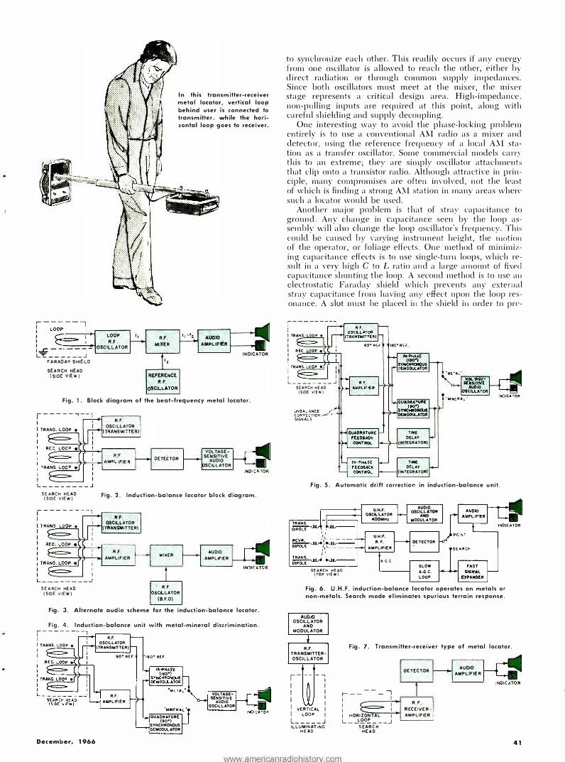
In this transmitter-receiver metal locator, vertical loop
behind user is connected to transmitter, while the horizontal loop goes to receiver.
'Auci10 "A .. PLIFlt'.R 1---... •I
INDICATOR
Fig. 1. Block diagram of the beat-frequency metal locator.
r----- ..... -- , I I TRANS. LOOP • I I
R,f OSCILLATOR
(TRANSMITTER)•
DETECTOR "VOl.TAGE· SENSITIVE
AUDIO SCllLATOR
SEARCH HEAD (SIDE VIEW) Fig. 2. Induction-balance locator block diagram.
· · RF OSCILLATOR
(TRANSMlTTERI
.RJ, -----'1-'!�'-->0I AMPLIFIER
SEARCH HEAD (SIDE VIEW)
MIXER
: R F. SCll .. LATOR
(8.F.O)
AUDIO AMPLIFIER
Fig. 3. Alternate audio scheme for the induction-balance locator.
Fig. 4. Induction-balance unit with metal-mineral discrimination.
r--------1 I I A.F. ! TRANS. LOOP •
I OSCILl..ATOA
I (TRANSMITTER)
I 90• REF. tao• REF.
December, 1966
R.F, AMPLIFIER
0-UADRATVRE (90•1 S YNCHRONOUS D!fttODULATOR
VOi.. T4G£S€NSITIVE
AUDIO OSCILLATOR
to synchronize each other. This readily occurs if any energy from one oscillator is allowed to reach the other, either hy direct radiation or through common supply impedances. Since both oscillators must meet at the mixer, the mixer stage represents a critical design area. High-impedance. non-pulling inputs are required at this point, along with careful shielding and supply decoupling.
One interesting way to a\'oicl the phase-locking prohlem cntirelv is to use a conYentional A�l radio as a mixer and detect<»r, using the reference frequency of a local A.\l station as a transfer oscillator. Some commercial models l«llT\' this to an extreme; they are simply oscillator attachments that clip onto a transistor radio. Although attracti,·e in principle, many compromises are often in\'olved, not the least of which is finding a strong A.\l station in many areas whcrl' such a locator would be used.
Another major problem is that of strav capacitance to ground. Any change in capacitance seen by the loop assemhly will also change the loop oscillator's frcqut•ncy. This c-ould be caused hy \"arying instnnnent height, the moti011 of the operator, or foliage effects. One method of minimil'.ing capacitance effects is to use single-turn loops, which result in a ,·ery high C to L ratio and a large amount of fixed capacitance shunting the loop. A second method is to use a11 electrostatic Faracla�· shield which pre\"ents an�· external stray capacitance from having anv effect upon the loop resonauce. A slot must he plac-ed in the shield i11 order to pre-
I TRAJllS. l..OOP • I I I I I
i'··§·· 1 1 . I IL..r-�--, L. ________ .J SE AA CH HE AO
(SIDE l/IEW)
TIME O(lAY
�INTEGRATOR)
T ... OE LAY
(INTEGRATOR)
Fig. 5. Automatic drift correction in induction-balance unit.
TRANS.
OIPOLE
U.H.f'. r---->-l 0.$Cll.l.ATOR
SEARCH HEAD (TOP VIEW)
400MHt
U.H.F. R.f'.
AMPLU:IER
A G.C.
AUOIO �CILl.ATOA
ANO MODULATOR
OETECTOR
SLOW A.G.C. LOOP
Fig. 6. U.H.F. induction-balance locator operates on metals or non-metals. Search mode eliminates spurious terrain response.
AUDIO . OSCILLATOR
ANO MODULATOR
R .F. TRANSMITTEROSCILLATOR
, ----, I I I I
I I
I VERTICAL : I LOOP I L _____ J ILLUMINAT1NG
HEAD
Fig. 7. Transmitter-receiver type of metal locator.
�-----..., : . I
: E=F : : I H ORIZONTAL l L __ L£0� ___ _J
SEARCH HEAD
DETECTOR
R F I RECEl�ER· ! AMPLIFIER 1
AUDIO ' AMPLIFIER
41
www.americanradiohistorv.com

vent the shield lrom acting as a shorted turn and severely lowering the "Q" of the search-loop assembly that is employed.
Induction-Balance Locator
This is a more sophisticated instrument of better sensiti\·ity and resolution. Depth penetration is better, yet still somewhat limited, and an excellent sensitivitv to tinv metallic objects can often be obtained. Fig. 2 sho�vs a ty1;ical block diagram. Three loop antennas are used, stacked vertic;1lly within the same search-head assembly. The top and bottom loops are connected to an r.f. oscillator; the middle one is connet:ted to a sensitive r.f. amplifier. The two transmitting loops are fed out-of-phase. Under no-target conditions, their induced voltages \·ery nearly cancel each other in the receiving loop, res11lting in very little net induced receiver voltage. The presence of a target below the bottom loop will upset the babnced induced voltages and produce a signal in the receiving loop. This unbalance signal is then am· plified and appears as an output.
The design problems here are entirely different from those of the beat-frequency locator. �Iechanical stability of the search head is very important, for the loops must be perfectly pla11ar. Temperature a11d stress can produce breathing of the loops, which can upset the induction balance. No metallic· fasteners should be used on the search head, and a minimum of metallic parts of any kind in the vicinity of the search head is highly desirable. A stable transmitter frequency, unaffected by search-head stray capacitance, is mandatory. In the more sophisticated designs, all circuitry must also be phase-stable and drift-free, particularly with respect to temperature or battery voltage.
Since modulating the r.f. source presents balancing problems, c.w. oscillators are normally used whose detected-target output voltage will be d.c. This output may be used to deflect a meter or power an integrated sonic module. Another alternative is to form an audio beat note with a second oscillator and mixer tuned to 1 kHz or so awav from the main transmitter. The beat note will have its amplitude proportional to target unbalance and can be amplified to power a loudspeaker or a pair of headphones. Such an alternate system is shown in Fig. 3.
Target Di�1:i-imination
Some fancy techniques allow the induction-balance loca-
tor to discriminate between conductive metallic targets and magnetic minerals such as black sand or soils with a high iron-ore content. This allows the locator to see through the remanent magnetism of the soil, greatly enhancing the sensitivity to marginal targets.
These techniques are accomplished by using the phase information in the received signal. The receiver and transmitter •lre inductively loose-coupled, so there will be a goo phase difference between the receiver voltage and the transmitter current. A conductive target will be inductively coupled twice, once from transmitter to target and once from target to receiver, so the receiver unbalance n>ltage due to a target will be phase-shifted twice go0, or 180°.
,\Jagnetic sands and rem;ment magnetism in soils will simply increase and distort the inductive coupling without introducing a resistive ( 180°) compon ent . Thus, there will be a go0 phase difference at the receiver between conductive targets on the one hand and magnetic soils on the other hand.
To discriminate between the two, two demodulators (detectors) are used, both of which are sy11c/1ro11i:::ed to the transmitted signal. An .. in-phase" ( 180°) demodulator will detect 011/y the return from conductive targets, while a "quadrature" ( go0) demodulator will detect only magnetic minerals. A '';\Ietal-.\Iineral'' selector switch is used to route the desired output to the indicators. Fig. -1 shows a block diagram of this type of locator.
Automatic Drift Correction
The induction-balance locator can also be made to automatically correct its own unbalance due to loop breathing, ground effects, and varying instrument height. Feedback techniques are used. The output of each phase detector is used to control the introduction of just enough in-phase and quadrature transmitter power of proper polarity to exactly buck out the unbalance signal at the input to the r.f. amplifier. Enough time delay (integration time) is introduced into the feedback path to allow the detection of targets. Otherwise, the target signals would be bucked out with the unbalance and no output would ever reach the indicators. Two to five seconds of delay allows the correction circuitry to keep up with gradual changes in soil conductivity and instrument height yet lets the sudden appearance of a target produce a strong output. One of many possible systems is outlined in Fig. 5. ( Conti1111ed 011 page 62)
Table 2. Comparative characteristics of the basic types of metal locators discussed in accompanying article.
' Beat·Frequency
Locator
� �i;-J
;;, ;-::::::> �r:::? .l { .
li1duction-Balance Locator
! j' C? l
� ���··,.,. -----��; � J�I,, � !&-PM
�Y T s tter·Re��-���r-
42
-·· Locator
.,. :\'on-synchronous : Synchronous
Indivi(lUal instruments will vary widely from pertormance suggested in this table.
1. DEPTH PENETRATION Maximum depth at which a small object produces a strong return
2. RESOLUTION Smallest object detect· able at four inches depth
3. WEIGHT Typical weight of commercial models
4. COST Typical economy commercial unit
Typical quality commercial unit
5. UNIQUE FEATURES
6. COMMON APPLICATIONS
BEAT·FREQUENCY LOCATOR
POOR
1 foot
GOOD
Ring or large coin
LIGHTEST
1·5 pounds
LEAST
$30
$80
Discriminates between magnetic and non·
magnetic conductors
Beachcombing. Local-ing lost jewelry
www.americanradiohistorv.com
INDUCTION·BALANCE TRANSMIITER·RECEIVER LOCATOR
BETTER
2 feet
EXCELLENT Metal nugget or
small coin
HEAVY
3· 15 pounds
LOCATOR
EXCELLENT
8 feet
POOR
3" sphere
HEAVIEST
9·25 pounds
MODERATE'' /HIGHEST"" HIGH $100" $150"''' $125
$200* $350"" $225
Can discriminate be- Can triangulate for tween conductive tar· depth indication g e t s a n d m a g n e t i c soils and ores"''
Exploring Pipe tracing Coin finding Prospecting
ELECTRONICS WORLD

NOW'"� A Complete Automotive and
Ignition Tune-Up System
MARK TEN Capacitive Discharge
Ignition System
$4495 Assembled
$29s5 Kit Form
Get m11eage you never dreamed of! 3 to
IO times spark plug l ife. Instant starts in all weather. Installs in only I O minutes.
Up to 20% gas savings. Dramatic increase in engine performance and acceleration.
2 N EW AUTO TUNE UP INSTRUMENTS
-. • -� '[T.imn../er� -
DWELL TACH METER METER
$12.95 $14.95 Ppd. Ppd.
These two new cousins lo the wor ld famous proven MARK TEN now give you the capability to tune your own car inexpensively, easily, with remarkable precision_ These separate instruments are low cost, portable and the easiest to read you've ever seen.
• Della's famous printed circuit design
• Superior in precision , quality and per· formance to instruments selling for FIVE TIMES as much
• large dial, high quality 1ewel D'arsonval meters
• Operates with standard. transistor or capacitive discharge systems as well as magnetos
• Instant readings - no confusing scales
Send Your Order Today -------
�DELTA PRODUCTS, INC. P. 0. Box 1147EW • Grand Junction, Colo.
Enclosed is $ --· Ship prepaid. D Ship C.0.0. Please send:
O Dwell Meters @ $12.95 D Tach Meters @ $14.95 D Mark Tens !Assembled) @ $44.95 D Mark Tens !Delta Kitl @ $29.95 (12 volt positive or negative ground only)
SPECIFY - 0 Positive 0 Ne gat ive D 6 or D 12 Volt
Car Year _____ Make ___ �-
Name _________ _
Address, ___ _ _
City/State__ lip __ _
-------OP 6·11 CIRCLE NO. 118 ON READER SERVICE CARD 62
Electronic Metal Locators (Co11ti1111cd from page 42)
U.H.F. Type This metal locator has several unique
operating features. Fig. 6 shows the block diagram. The u.h.f. locator is <:apable of detecting either metallic or non-rnetallic objects ancl is able to cliscriminate between these objects and the normal clutter of rock discontinuities. Operatio11 is somewhat similar to the indu<:tion-balance locator, except that the operating frequency is 400 '.\lHz and I he loops arc replaced by a search array consisting of inductively loaded dipole antennas. Two transniitting tlipoles are used with a receiver dipole between them. A figure-eight pattern is produced in the absence of any target, resulting in halancecl voltages that nearly cancel i11 the receiver dipole. The presence of any object of uniformly different conductivity and dielectric constant from the surrounding medium upsets the balance and produces an output signal.
There art· t\H> modes of operation, the "Search" mode and the "Point" mode. ln the "Search" mode, all of the spurious return is averaged out by a long time constant a.g.c·. loop, while any sudden changes in the field patterns are greatly amplified by an expander circuit, indicating the edge of a target diret'tly below the search array. In the "Point" mode, the recei,·er output is amplitude-sensitiYe and the instrument may be used to outline the buried object. The u.h.f. locator is principally used by the military for the detection of metallic and non-metallic mines.
Tran:;m i tter-R<'CI' in'r l 11�t rumen t Of the popular locator types, the
transmitter-recei,·er i1 1strument is capable of the deepest penetration and is principally nsed for large-object detection, such as locating buried pipes and trat'ing mineral Yeins. \la11v instruments of this type ca11 also give a relative indication of the depth of target hmial by a triang11hition method. Utility companies as well as amateurs make t·xtcnsi\·e use of this particular type of instrnment.
I f t\\"O loop antennas are placed at right angles to each other so that one loop is positioned directly along the null axis of the other, 110 signal coupling between the two will exist. In practice, one loop is excited with an r. f. oscillator-transmitter. This is usually the vertical rear loop. The other loop forms the front encl of a highly sensitive r.f. receiver-amplifier followed by a detector and indicator, as shown in the block diagram of Fig. 7.
In the absence of targets, the received signal is zero because of zero
www.americanradiohistorv.com
mutual inductance between receiver and transmitter; any energy inductively coupled da a target produces a receiver signal in proportion to the size and location of the target.
'.\laximum signal return occurs when the target is almost centered under the receiver loop. For the first few feet of target depth, the distance from tra11s-111ittcr to large:! changes \'ery little. In addition, more energy is actually delivered to a deeper target than to a very shallow one, clue to the field patterns of tl1e transmitting loop. For these two reaso11s, the transmitter-receiver locator retains a ,·ery good penetration capability to depths comparable to the instrument length. Only for depths substantially greater than the transmitter and receiver separation does the signal return begin to fall off as the sixth power of depth.
The price paid for the good penetration is inability to resolve small objects. \\'hen <I target is in the position of opti11111111 detectability, it is at least four feet awav from the transmitter and thus must be physically large to intercept enough trnnsmittcr energy to produce a useful recei\'er ,-oltage. The majority of transmitter-receiver locators are incapable of detecting an object less than three inches in diameter, e\'en if the target is on the surface.
Synchronous dcmoclulation may be employed 011 the transmitter-receiver locator, but only if totally balanced circuitry is used. Otherwise, the interco11-11ectio11 between receiver and transmitter will itself radiate and distort the normal field patterns.
Design problems include mechanical stability and the minimum use of metal parts in assembly, for either of these factors can t'limi11ate the sl1arp null obtained at 90 ° positioning and greatly reduce apparent sensitivity.
Co111111crcial Instruments Table 1 lists major manufacturers of
electronic metal locators intended for sport applications. Table 2 gives the relative performance capabilities of the three sport types in terms of relative cost, penetration, resolution, weight, and applications. Individual commercial instntments will \'ary widely from the ,-alucs sl 1own, depending upon soil conditions, operator experience, the quality of the instrument, and other factors.
I 11 addition to the sport types covered here, there are a number of industrialtype metal locators that are used by the 11tility companies and others. In general, the operation and characteristics of these metal locators are very similar to the sport types co\·ered, although the industrial types may be more expensive and constructed to withstand more physical abuse than a unit that is only used occasionally would encounter. A
ELECTRONICS WORLD