Electronic Instrumentation Basic Circuits with BJT...
31
Electronic Instrumentation Basic Circuits with BJT Transistors * In this presentation definitions and examples from Wikipedia, HowStaffWorks and some other sources were used Lecturer: Dr. Samuel Kosolapov
Transcript of Electronic Instrumentation Basic Circuits with BJT...

Electronic InstrumentationBasic Circuits with BJT Transistors
* In this presentation definitions and examplesfrom Wikipedia, HowStaffWorks and some other sources
were used
Lecturer: Dr. Samuel Kosolapov

Items to be defined/refreshed/discussed
• BJT as a switch
• Basic BJT Amplifiers Configuration
• Common Emitter
• Common Collector (Emitter Follower, Buffer)
• Common Base
• Summary of configurations properties
• Examples with Arduino
2

Basic BJT (pnp and npn – most of modern transistors)http://blog.oscarliang.net/bjt-bipolar-junction-transistor-beginner-tutorial/
3
Pin allocations may be different
http://www.talkingelectronics.com/pay/BEC/Page21.html

BJT equivalent circuitshttp://electronics-course.com/bipolar-junction-transistor-bjt
4

BJT as an (invertor) switchhttp://blog.oscarliang.net/bjt-bipolar-junction-transistor-beginner-tutorial/
5
Need for BJT Switch:Arduino max per pin current ~ 40 mAThis current may be too small to drive solenoids, motors, etc.
BJT can provide current gain (Ic >> Ib)
BJT as an (invertor) switchhttp://blog.oscarliang.net/bjt-bipolar-junction-transistor-beginner-tutorial/
6
Work Line: Vcc = Vce + Ic*Rc
Vin = 0 (LOW) : Vout = Vcc (HIGH)Vin = ~VCC (HIGH) : Vout ~0 (LOW)

BJT as an (invertor) switch. Equations for Fast Evaluationshttp://blog.oscarliang.net/bjt-bipolar-junction-transistor-beginner-tutorial/
7
BJT Switch Large Signal (DC) Equivalent Circuit
Irb = Ib ; Ic = b*Ib; Ie = Ib + Ic ; Vb = Ib*Rb + VbeVc = Ic*Rc + Vce Vc = b*Ib*Rc + Vce
If Vce < 0.2 V : Transistor is FULLY ON Vce ~ 0 Vc = Ic*Rc(Then equation Ic = b*Ib is not valid). Trick: use it as if it is still valid to make fast evaluations

Practical BJT switching circuithttp://www.electronics-tutorials.ws/transistor/tran_4.html
8
(Varduino_out – Vswitch_in ) / Rb = Ib <= 40 E-3A;We do not want to burn Arduino PinWorst case:Varduino_out = 5V; Vswitch_in = 0.7 V Rb minimal value:
Rb > (5 – 0.7) / 40E-3 ~ 100 W
We want to provide LARGE current to the LOADThe calculation trick is that transistor is
STILL in the active region: Ic = b * IbSuppose, we want Ic = 100 mA and b = 100 Ib -= 1
mA
(Varduino_out – Vswitch_in ) / Rb = IbRb maximal value:
Rb < (5-0.7) / (Ic/b)
Rb < (5 – 0.7) / 1E-3 ~ 43 kW

Practical BJT switching circuitshttp://www.electronics-tutorials.ws/transistor/tran_4.html
9

Basic BJT Amplifier Configurationshttp://people.seas.harvard.edu/~jones/es154/lectures/lecture_3/bjt_amps/bjt_amps.html
10
Common Input and Output pin Common Emitter; Common Base; Common Collector
http://www.talkingelectronics.com/pay/BEC/Page21.html

Small Signal BJT Amplifier Operationhttp://www.slideshare.net/_IrfanAnsari/l7-bjt-amplifier-26289398
11

Small Signal BJT Amplifier Operation: Graphical Analysishttp://www.slideshare.net/_IrfanAnsari/l7-bjt-amplifier-26289398
12

Generalized Common Emitter: Detailed Analysishttp://people.seas.harvard.edu/~jones/es154/lectures/lecture_3/bjt_amps/bjt_amps.html
13
Actual circuit
Small-Signal Equivalent Circuitready for Voltage Node Analysis
In the Medium Frequencies(Decoupling capacitors are C1 and C2 “large”.
Ce value will be set LATERParasite capacitors are “negligibly small”)
BJT Model with Y-parameters used

Generalized Common Emitter: Voltage Node Equations
http://people.seas.harvard.edu/~jones/es154/lectures/lecture_3/bjt_amps/bjt_amps.html
14
Or

Generalized Common Emitter: Voltage Gain
http://people.seas.harvard.edu/~jones/es154/lectures/lecture_3/bjt_amps/bjt_amps.html
15
Case Re = 0 (Or Ce is LARGE) (Classic Common Emitter)
Case Re != 0 (Or Ce is absent) (Generalized Common Emitter)
Important concept: desensitivity:If b is LARGE Av ~ Rc/Re : No dependence on b
Input Resistance: LOW (~ 1 kW)Many sensors cannot be
connected directly to CE

Generalized Common Emitter: Input Resistance
16
Case Re = 0 (Or Ce is LARGE) (Classic Common Emitter)
Case Re != 0 (Or Ce is absent) (Generalized Common Emitter)
Input Resistance: LOW (~ 1 kW)Many sensors cannot be
connected directly to CE
Input Resistance: MEDIUM (~ b*Re ~ 50 kW) More sensors can be connected directly to CE
(But Av is small)
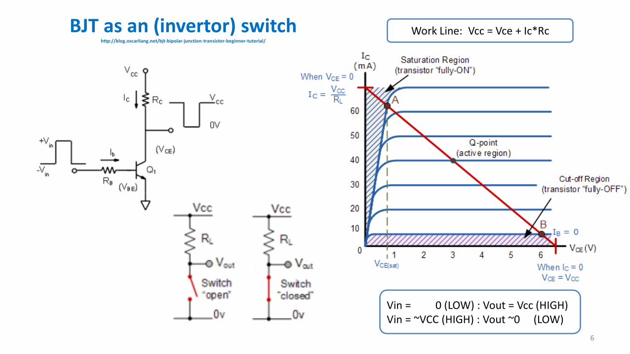
Common Collector: Basic Circuits http://people.seas.harvard.edu/~jones/es154/lectures/lecture_3/bjt_amps/bjt_amps.html
17

Common Collector (Emitter Follower): Operation http://people.seas.harvard.edu/~jones/es154/lectures/lecture_3/bjt_amps/bjt_amps.html
18

Common Collector: Detailed Analysis
http://people.seas.harvard.edu/~jones/es154/lectures/lecture_3/bjt_amps/bjt_amps.html
19
Or

Common Collector: Voltage Gain. Input and Output Resistance
http://people.seas.harvard.edu/~jones/es154/lectures/lecture_3/bjt_amps/bjt_amps.html
20
If b LARGE Av ~ 1 Buffer
Input Resistance is LARGE (~ 500 kW )
Output Resistance is SMALL (~ 10 W )

Common Collector: Example. Using High Input and Low Output Resistance
21
Input Resistance is LARGE (~ 500 kW )
~ No loading effect for Photo resistor sensor
Output Resistance is SMALL (~ 10 W )
Enough current for LED

Common Base Amplifier
22
Useful for High Frequencies (Because of absence of Miller Effect)

BJT Amplifiers Summary (see Sedra and Smith book)
23

BJT Amplifiers Practical Examples with Arduino. Sensors. Microphone Amplifier
24
Electret microphone already has a preamplifier inside.But if we need more sensitive microphone, additional BJT amplifiers can be used
(discuss designs advantages and disadvantages)

BJT Amplifiers Practical Examples with ArduinoActuators: Speaker
25
Small Speaker can be connected to ArduinoBut : Arduino can deliver up to 40 mA current per pin protected resistor ~ 100 W neededSimple connection, BUT:Rsp ~ 10 W; Vsp ~ 0.1 *5V (voltage divider); Psp ~ Vsp*Vsp / Rsp ~ 30 mW Power on the speaker will be LOW
Additional Amplifier is needed
With Arduino UNO Tone Library is typically used to produce DIGITAL sounds (ON-OFF pulses) Linearity is not required
Buzzer volume is small.If we need strong audio signal, speaker must be used

BJT Amplifiers Practical Examples with ArduinoActuators: Speaker. Connection with Transistor
26
Explain diode usage (Hint: Speaker is actually a coil)Discuss Buffer alternative (R = 100 W)
Both circuits are for amateurs only. Power Amplifier must be used with serious speaker (details later)

BJT Amplifiers Practical Examples with ArduinoActuator. Powerful External Relay Driver
27

BJT Amplifiers Practical Examples with ArduinoActuator. Motor Driver
28
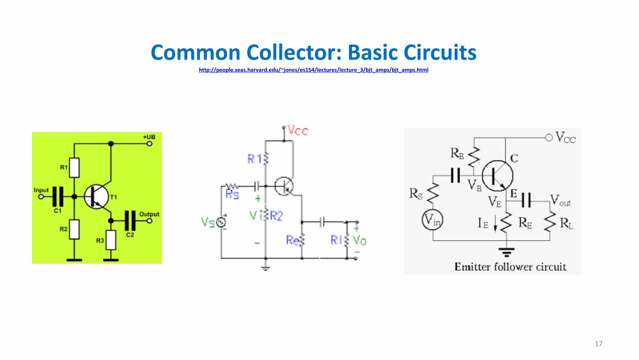
BJT Amplifiers Practical Exampleswith Arduino Actuators
29

Control Questions
• What have I learned ?
30

Literature to read
1. TBD
31


![Chapter 5 BJT Biasing Circuits Engineering/833... · 2017. 12. 8. · BJT Biasing Circuits 5.1 The DC Operation Point [5] DC Bias: Bias establishes the dc operating point for proper](https://static.fdocuments.in/doc/165x107/6109b3612d57d967952ea81a/chapter-5-bjt-biasing-circuits-engineering833-2017-12-8-bjt-biasing-circuits.jpg)
