
Electronic ignition system - POWER SPARK · assembled in the engine and the ca connected. Do not...
44
Installation and operating manual Electronic ignition system Versions: • 1 cylinder RC-i 100, RC-i 120 • 2 cylinders RC-i 200, RC-i 220 (twin, 180° ignition offset) • 3 & 4 cylinders RC-i 400, RC-i 420 (double-twin, 180° ignition offset) included: • POWER SPARK • speed sensor • magnet for speed sensor • 2x bushings for speed sensor • programming magnet • installation and operating instructions
Transcript of Electronic ignition system - POWER SPARK · assembled in the engine and the ca connected. Do not...

Installation and operating manual
Electronic ignition system
Versions: • 1 cylinder RC-i 100, RC-i 120
• 2 cylinders RC-i 200, RC-i 220 (twin, 180° ignition offset)
• 3 & 4 cylinders RC-i 400, RC-i 420
(double-twin, 180° ignition offset)
included:
• POWER SPARK • speed sensor • magnet for speed sensor • 2x bushings for speed sensor • programming magnet • installation and operating instructions

POWER SPARK RC-i xxx
1) Only receiver control versions RC-i x2x,
Dear customer, thank you for your purchase.Please read the following instructions carefully, so you wouldn`t have any difficulties to install and operateWe wish you a successful installationPOWER SPARK.
We are always interested in feedback. Please contact:
tne.systeme
Dipl.-Ing. T. NiedermayerAlemannenstr. 7 D-73457 Essingen GERMANY
Tel: +49 7365 9191-41 email: [email protected]: www.power-spark.de
SEVERE WARNING
The ignition system produces electromagnetic interfering fields as well as high voltages at the spark coil and the spark plug.interfering fields are sufficiently screenedassembled in the engine and the caconnected.
� Do not touch
plug if the ignition system is activated.
HIGH VOLTAGE
� Make sure, that you do not
are sensitive to
devices that are life
etc.) if the ignition system is active.
Warranty
We guarantee the function ofbeginning on the day of purchase.installation make an exception of the guarantee.
i x2x, 2) only multiple cylinders versions RC-i 2xx & RC-i 4xx
hank you for your purchase. ase read the following instructions carefully, so you wouldn`t have any
operate the POWER SPARK. a successful installation and much pleasure using
We are always interested in improvements and look forward to your
Niedermayer
.de .de
The ignition system produces electromagnetic interfering fields as well as high voltages at the spark coil and the spark plug. Th
sufficiently screened if the spark plug is and the cables are professionally
Do not touch non insulated cables or the spark
plug if the ignition system is activated.
HIGH VOLTAGE, MORTAL DANGER
Make sure, that you do not use any attachments
are sensitive to electromagnetic interfering fields
are life-supporting (heart pacemaker
etc.) if the ignition system is active.
We guarantee the function of the „power spark” two years beginning on the day of purchase. Damages as a result of improper
n make an exception of the guarantee.
ase read the following instructions carefully, so you wouldn`t have any
and much pleasure using the
and look forward to your
The ignition system produces electromagnetic interfering fields as These
if the spark plug is
the spark
any attachments that
interfering fields or
supporting (heart pacemaker
Damages as a result of improper
!

POWER SPARK RC-i xxx
1) Only receiver control versions RC-i x2x, 2) only multiple cylinders versions RC-i 2xx & RC-i 4xx
All trademarks are industrial property of the respective owners. 2010.6 © tne.systeme Modifications and errors excepted. page 2
General
• micro controlled, high-precision electronic ignition system
• constant spark energy in the complete speed range
• spark energy independent from supply voltage, integrated voltage booster compensates voltage swing
• 2-digit brilliant red LED display
• simple installation and programming
• numerous possibilities to customize
• red anodized, waterproof aluminum housing
• speed up to 30000rpm with one or more cylinders2)
• display of the actual engine speed
• ignition starts at a minimum engine speed (safe start-up)
• separate ignition endstages2) => low power consumption when using multiple cylinders, (because additional cylinders ignite separately and
not parallel to the first one)
• no need of an additional battery pack, ignition system can be powered from the receiver battery pack (min. 4 batt.= 4,8V)
adjustment possibilities
• 9 pre-programmed ignition maps
• application of custom ignition map
• adjustable speed sensor angle (mechanical sensor offset)
• adjustable ignition energy (3 steps)
diagnosis features
• display of maximum engine speed and battery voltage
• supervision of main battery voltage
• low voltage warning (generation of ignition misses)
• engine stops if low voltage detected
• supervision of receiver battery voltage1)
• supervision of receiver servo signal1)
• free definable supervision window => engine stops if FAILSAFE-signal is detected
• „killswitch“- functionality
Features

POWER SPARK RC-i xxx
1) Only receiver control versions RC-i x2x, 2) only multiple cylinders versions RC-i 2xx & RC-i 4xx
All trademarks are industrial property of the respective owners. 2010.6 © tne.systeme Modifications and errors excepted. page 3
Backfitting an engine with magnetic ignition system
The POWER SPARK ignition was designed in a way that the original magneto ignition can be replaced with few modifications. This installation and operating instruction describes the modifications using the example of the ZENOAH-260-PUM- engine. The modifications of other engines can be done in the same way; deviations can result in the geometry of the flywheel, the fitting of the speed sensor etc.
Advantages of the POWER SPARK
Elimination of red primary ignition coil and flywheel with integrated magnets.
• smoother engine running, since the unsymmetrical magnetic brake torque for generating the ignition spark is eliminated
• allows the assembly of compact engines with more cylinders, because the prime-ignition coils are inapplicable.
Replacement of the original flywheel with integrated magnets.
• flywheel with increased inertia can be used (accessories) � increased engine smoothness � reduced idle speeds possible
The original secondary ignition coil(s) are used furthermore.
• Instead of the red primary ignition coil the POWER SPARK is connected to the secondary ignition coil. � high voltage circuit only between secondary ignition coil
and spark plug � no high voltage at POWER SPARK
• secondary ignition coil(s) do not have to be mounted to the engine

POWER SPARK RC-i xxx
1) Only receiver control versions RC-i x2x, 2) only multiple cylinders versions RC-i 2xx & RC-i 4xx
All trademarks are industrial property of the respective owners. 2010.6 © tne.systeme Modifications and errors excepted. page 4
The POWER SPARK has a lot of adjustment possibilities and functions. To ensure a fast assembly and initial startup, please act according to the following checklist. Assembly
□ attend safety and assembly instructions p.05
□ assemble POWER SPARK p.06
□ assemble magnet of speed sensor into new flywheel p.07 (if own flywheel is used)
□ assemble speed sensor to engine p.07
□ perform wiring p.10 / 11
Programming
□ check mechanical position of speed sensor p.30
□ possibly adjust sensor angle of speed sensor p.29
□ choose ignition map p.20
Initial startup
□ adjust speed limit p.27
□ start engine and perform a test run □ possibly choose another ignition map p.20
□ activate monitoring functions p.35
Quick way to success

POWER SPARK RC-i xxx
1) Only receiver control versions RC-i x2x, 2) only multiple cylinders versions RC-i 2xx & RC-i 4xx
All trademarks are industrial property of the respective owners. 2010.6 © tne.systeme Modifications and errors excepted. page 5
Safety and installation instructions
Please read the following instructions carefully. Please work carefully. Do not pull on cables or cable connections. Improper cable connections may result in cable fires by reason of short circuits. Improper cable installations or cable connections may result in malfunction or damages to the components. Correct positioning and connection of cables is essential for long term, error free function of the POWER SPARK.
The connector plugs of the sensor cable have adjustments, please notice that and plug in the connector very carefully to avoid damage of pins.
- Install the cables in zero potential state, disconnect all battery packs. - Do not locate the cables near sharp edges or hot or moving parts, so that they cannot be damaged. - To connect the cables use only suitable connectors. Make sure, that the cables have a good contact and that the conductive parts of the connector cannot be touched when connected. - Install the cables, especially the sensor cable and the cable to the
RC-receiver as far as possible from the ignition coils to avoid
interference.
- To avoid short circuit or damages of components isolate non-used
cables with insulating band or insulating screw joints.
- If possible, install the plug-in connectors at a suitable place where no splash water or other liquids like petrol or oil can reach them and keep care that they cannot detach from their place (use tape or cable binders).
- Please ask an expert if you have problems with the installation.
We are not responsible for consequential damages
by installing and using the POWER SPARK . !

POWER SPARK RC-i xxx
1) Only receiver control versions RC-i x2x, 2) only multiple cylinders versions RC-i 2xx & RC-i 4xx
All trademarks are industrial property of the respective owners. 2010.6 © tne.systeme Modifications and errors excepted. page 6
Assembly of the POWER SPARK
Please note the following points when installing the POWER SPARK:
• mechanic installation
o the housing of the POWER SPARK can get hot when running the engine with high speeds over a long period => do not install heat sensitive components near the POWER SPARK => make heat dissipation possible (don`t cover) => install in an adequate distance to the engine
o install at a place with low vibration o choose the position so that the display of the POWER SPARK
can be read easily o choose the position that the magnetic sensitive element for
programming the POWER SPARK is accessible. (see programming)
o ensure a robust mechanical installation of the POWERSPARK (for example with special brackets for laminating) (accessories: assembly set, item-nr.: EB-1)
o the dimensions of the POWER SPARK and the distances of the fastening bores shows the scale on page 43.
• electric installation
o engines with more than one cylinder and engine speeds exceeding 20000rpm need battery packs with minimum 9V supply voltage
o keep the supply cables (red & black) as short as possible o keep the cables to the ignition coils as short as possible o don`t place the cables to the ignition coils near signal cables
(for example the cables to the servos) o place the signal cable to the speed sensor and to the RC-
receiver1) in an adequate distance to the ignition coils
o fuse the plus cable of the POWER SPARK
(accessories: SI-3, SI-5, Si-10) � fuse 3A (for versions RC-i 1xx)
� fuse 5A / 10A (for versions RC-i 2xx / RC-I 4xx) o establish a ground connection from the engine to the battery
minus with a cable of at least 1,5mm² cross section

POWER SPARK RC-i xxx
1) Only receiver control versions RC-i x2x, 2) only multiple cylinders versions RC-i 2xx & RC-i 4xx
All trademarks are industrial property of the respective owners. 2010.6 © tne.systeme Modifications and errors excepted. page 7
Installation of speed sensor
A precise ignition to the right time assumes the correct assembly of the speed sensor to the engine. The magnet and the speed sensor have to be installed in a way that, during a rotation, the speed sensor is triggered by the magnet 75° before reaching the top dead center. As the sensing magnet is surrounded by a magnetic stray field, the speed sensor will be triggered about 10° before passing the magnet mechanically. For this reason the sensing magnet must pass the speed sensor 65° before the top dead center. The value of the stray magnetic field about 10° applies to the shown geometry (see illustration). When installing the magnet on an increased radius the pre-triggering of the speed sensor decreases.
Speed sensor
� Install speed sensor at an adequate place to the engine
• Assemble the speed sensor with M3 screws. For protecting the strip conductors put the provided bushings under the screws. (see d)
• the magnet in the flywheel and the speed sensor element have to be at the same level (see c,d) The exact adjustment can be made with the help of two 0,5mm- holes in the area of the speed sensor`s sensitive element, you can find the sensitive element in the middle of the connecting line between the two holes.
• the speed sensor`s flattened side faces the flywheel (see d)
• set the air gap between the speed sensor and the flywheel between 0,5mm - 1,5mm. (see d)
magnet
� place the magnet (Ø3mm, length 4mm) into the flywheel in a way:
• that it passes the speed sensor in direction of rotation 65° before reaching the top dead center (a,b) For checking the sensor angle use the menu „CS“ (p.30), and correct it with menu „SA“ (p. 29).
• that the surface of the magnet is located max. 1mm under the surface of the flywheel (d)
• that it is permanently fixed (for example use instant adhesive). The polarity of the magnet can be ignored.

POWER SPARK RC-i xxx
1) Only receiver control versions RC-i x2x, 2) only multiple cylinders versions RC-i 2xx & RC-i 4xx
All trademarks are industrial property of the respective owners. 2010.6 © tne.systeme Modifications and errors excepted. page 8
Detail description of magnet and speed sensor
• Presentation a,b: cylinder 1 is on top dead center
���� HINT: For fine adjustment use menu „control sensor” (p.30) in the configuration menu.
magnet
flywheel
25mm 35mm
29,5mm
flywheel
magnet
c d
bushing
sensor
65°
sensor
65°
magnet magnet
flywheel flywheel
rotation „left“ (reverse) direction rotation „right“ (normal)
a b
sensing element
air gap 0,5..1,5mm

POWER SPARK RC-i xxx
1) Only receiver control versions RC-i x2x, 2) only multiple cylinders versions RC-i 2xx & RC-i 4xx
All trademarks are industrial property of the respective owners. 2010.6 © tne.systeme Modifications and errors excepted. page 9
Connections
Pin assignment of POWER SPARK
color Function cross section length
red + supply (4..12V), use fuse (value see p. 43)
1 mm² 25 cm
black - supply (earth) 1 mm² 25 cm
pink + supply ignition coil 1 1 mm² 35 cm
pink2) + supply ignition coil 22) 1 mm² 35 cm
white - supply ignition coil 1 1 mm² 35 cm
yellow2) - supply ignition coil 22) 1 mm² 35 cm
Pin assignment of RC-receiver-cable 1)
color Function cross section length
white + voltage receiver (3..12V) 0,14 mm² 21 cm
green receiver signal (servosignal) 0,14 mm² 21 cm
brown - voltage receiver (earth) 0,14 mm² 21 cm
green
brown
white
1) only RC-receiver control versions RC-i x2x
2) only multiple cylinders versions RC-i 2 xx
ly
RC-receiver 1)
speed sensor
grey cables cables
red
RC
-i x
xx
POWER SPARK
black
pink
pink 2)
white
yellow 2)

POWER SPARK RC-i xxx
1) Only receiver control versions RC-i x2x, 2) only multiple cylinders versions RC-i 2xx & RC-i 4xx
All trademarks are industrial property of the respective owners. 2010.6 © tne.systeme Modifications and errors excepted. page 10
Connecting diagram 1
exemplary for POWER SPARK RC-i 220:
• shared battery pack (accu) for receiver and POWER SPARK
important: ���� insulate non-used cables with insulating tape
���� elongate cables only with min 1,5mm² cables
RC
-i 2
20
POWER SPARK
engine
ZS 1
ic 1
ZS 1
ic 2
sensor
RC- receiver
accu+ -
+ -
mass connection to engine housing
con
ne
cto
r
yelloww
white
pink
pink
red
red
red
fuse
black
min. 1,5mm²

POWER SPARK RC-i xxx
1) Only receiver control versions RC-i x2x, 2) only multiple cylinders versions RC-i 2xx & RC-i 4xx
All trademarks are industrial property of the respective owners. 2010.6 © tne.systeme Modifications and errors excepted. page 11
Connecting diagram 2
exemplary for POWER SPARK RC-i 220:
• separate battery packs for receiver and POWER SPARK � mass connection established between batteries
important: ���� insulate non-used cables with insulating tape
���� elongate cables only with min 1,5mm² cables
yellow
white
pink
pink
RC
-i 2
20
POWER SPARK
engine
ZS 1
ic 1
ZS 1
ic 2
sensor
ignition accu
+ -
+ -
Mass connection to engine housing
con
ne
cto
r
red
black
red
red
RC- receiver
RC- accu + -
+ -
m
fuse
min. 1,5mm²
m

POWER SPARK RC-i xxx
1) Only receiver control versions RC-i x2x, 2) only multiple cylinders versions RC-i 2xx & RC-i 4xx
All trademarks are industrial property of the respective owners. 2010.6 © tne.systeme Modifications and errors excepted. page 12
Connection of ignition coil
The POWER SPARK conducts the ignition pulse via the white or yellow cable to the ignition coil`s ground connection. The ground connection of the ignition coil must not have an electric contact to the engine housing, contrary to the original application. Furthermore it has to be insulated to avoid accidental touching.
Modification of ignition coil (Proposal on application of an insulating bushing that is available as accessories, item-nr.: IB-1)
original state - ignition coil with electrically conductive metal bushing (1)
� drilled out bushing - use drill with Ø 6,2mm
� (3) connection of white/ yellow cable with eye
(4) insulation bushing (access.) (5) grommet (6) screw M4
� (7) insulate the electrically conductive components, for example with silicone or adhesive tape
ZS 1
ic
7
ZS 1
ic 3
4
5
6
ZS 1
ic 2
ZS 1
ic 1
engine
ZS 1
ic ground connection of ignition coil - must not have contact to engine housing - must be insulated to avoid accidental touching (high voltage!)
white or yellow
pink
red

POWER SPARK RC-i xxx
1) Only receiver control versions RC-i x2x, 2) only multiple cylinders versions RC-i 2xx & RC-i 4xx
All trademarks are industrial property of the respective owners. 2010.6 © tne.systeme Modifications and errors excepted. page 13
General
To make the programming as simple as possible, the POWER SPARK can be programmed with the provided programming magnet. In the left bottom corner there is a magnetic sensitive element that can be triggered by approaching the programming magnet.
By approaching the programming magnet parallel to the left side of the POWER SPARK (sideways or from top, position a) ) in a distance of less than 10 mm the magnetic sensitive element is triggered. The POWER SPARK confirms the activation and shows „ . . “ additional to the active display.
Programming - essentials
RC
-i x
xx
a)
b)
magnet
RC
-i x
xx
cables
POWER SPARK
magnetic sensitive element

POWER SPARK RC-i xxx
1) Only receiver control versions RC-i x2x, 2) only multiple cylinders versions RC-i 2xx & RC-i 4xx
All trademarks are industrial property of the respective owners. 2010.6 © tne.systeme Modifications and errors excepted. page 14
� After that confirmation remove the magnet. Alternatively the programming magnet can be approached along the bottom side (position b), see figure. If there is few space the programming magnet can also be approached vertically to the magnetic sensitive element.
c) Approach the magnet vertical from the left side to the bottom left corner. d) Alternatively approach the magnet vertical from the bottom to the bottom left corner of the POWER SPARK.
Symbolic
display: „1.2“ => no input expected
display: „1.2“, flashing => user input expected
display: „1.2“ „1“ flashing, „2“ not flashing => user input expected
display: „Ξ“
modified values are stored
acceptable range of values (0 to 9)
� action of operator required
0..9
c)
d)

POWER SPARK RC-i xxx
1) Only receiver control versions RC-i x2x, 2) only multiple cylinders versions RC-i 2xx & RC-i 4xx
All trademarks are industrial property of the respective owners. 2010.6 © tne.systeme Modifications and errors excepted. page 15
Menu structure
The operation of the POWER SPARK results by selection of the desired set or displayed parameters by approaching and removing the programming magnet.
The parameters are arranged in three main menu groups
• configuration menu „Co“ o engine adjustments, that are changed rarely
• status menu „||||“ o displays actual values
• diagnostics menu „dd“ o modifying of diagnostic parameters
A parameter can be modified by the following procedure
• select the according main menu - the adjustable menu items flash one after another for 3sec
• confirm the desired menu item by approaching and removing the programming magnet - (for confirmation the display shows „ . . “ additionally)
• display shows the actual value of the parameter
• selection of values by the user - adjustable values flash one after another for 3sec
• confirm the desired menu item by approaching and removing the programming magnet (possibly several times)
• display shows the new modified values
• POWER SPARK returns to the normal operation mode (display of engine speed)
Annotations
• the configuration menu can only be activated when the POWER SPARK is turned on
• the status- and diagnostic menus can be called only when the engine is not running
• the POWER SPARK returns to the normal operation mode (display of engine speed and ignition standby) if no confirmation happens during the changing displays of the individual menu items
• if no confirmation (with the programming magnet) happens during the change of any value, the prior values will be retained
POWER SPARK RC-i xxx
1) Only receiver control versions RC-i x2x, 2) only multiple cylinders versions RC-i 2xx & RC-i 4xx
All trademarks are industrial property of the respective owners. 2010.6 © tne.systeme Modifications and errors excepted. page 16
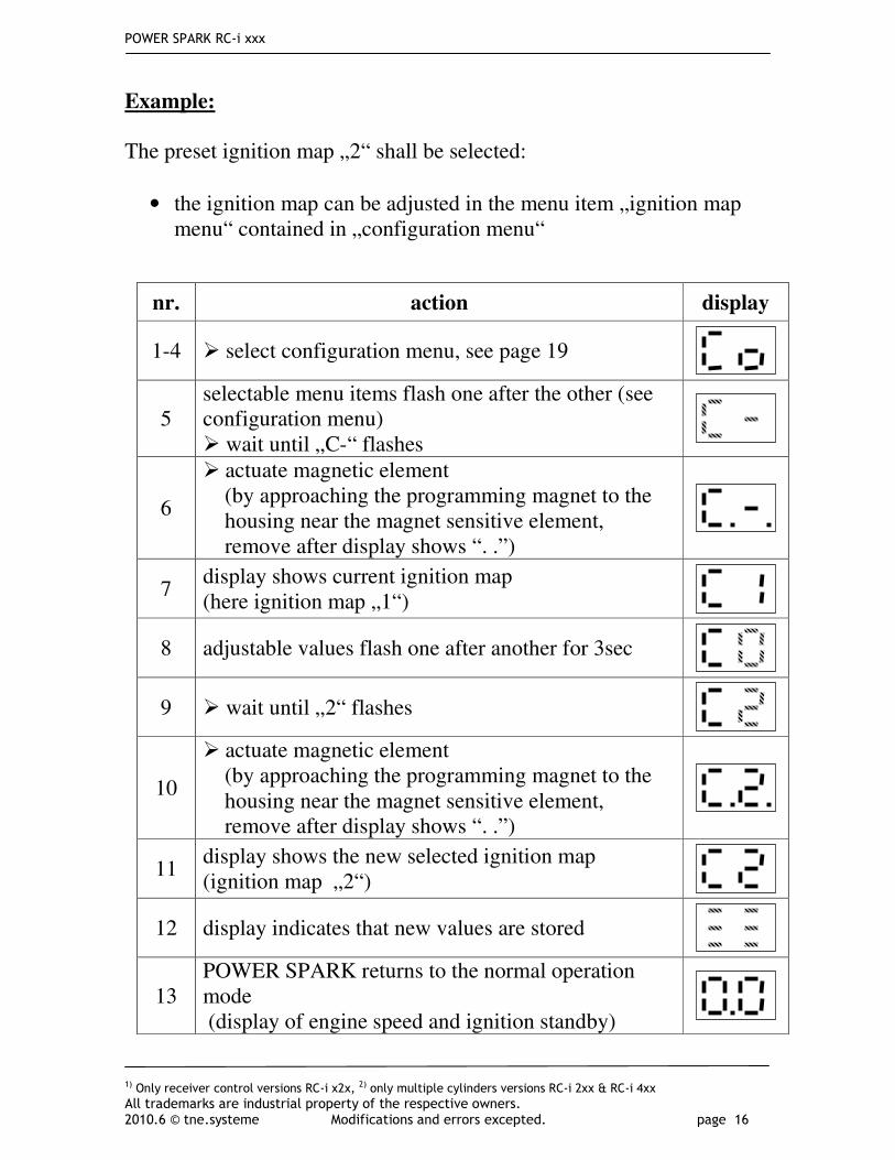
Example:
The preset ignition map „2“ shall be selected:
• the ignition map can be adjusted in the menu item „ignition map menu“ contained in „configuration menu“
nr. action display
1-4 � select configuration menu, see page 19
5 selectable menu items flash one after the other (see configuration menu) � wait until „C-“ flashes
6
� actuate magnetic element (by approaching the programming magnet to the housing near the magnet sensitive element, remove after display shows “. .”)
7 display shows current ignition map (here ignition map „1“)
8 adjustable values flash one after another for 3sec
9 � wait until „2“ flashes
10
� actuate magnetic element (by approaching the programming magnet to the housing near the magnet sensitive element, remove after display shows “. .”)
11 display shows the new selected ignition map (ignition map „2“)
12 display indicates that new values are stored
13 POWER SPARK returns to the normal operation mode (display of engine speed and ignition standby)

POWER SPARK RC-i xxx
1) Only receiver control versions RC-i x2x, 2) only multiple cylinders versions RC-i 2xx & RC-i 4xx
All trademarks are industrial property of the respective owners. 2010.6 © tne.systeme Modifications and errors excepted. page 17
Overview configuration menu

POWER SPARK RC-i xxx
1) Only receiver control versions RC-i x2x, 2) only multiple cylinders versions RC-i 2xx & RC-i 4xx
All trademarks are industrial property of the respective owners. 2010.6 © tne.systeme Modifications and errors excepted. page 18
Overview status- and diagnostics menu
only versions RC-i x2x

POWER SPARK RC-i xxx CONFIGURATION MENU
1) Only receiver control versions RC-i x2x, 2) only multiple cylinders versions RC-i 2xx & RC-i 4xx
All trademarks are industrial property of the respective owners. 2010.6 © tne.systeme Modifications and errors excepted. page 19
CONFIGURATION MENU
The configuration menu includes the following menu items
a) ignition map menu
selection of one of nine pre-programmed ignition maps b) ignition map individual
configuration of one custom ignition map c) speed limit
adjustment of engine speed limit (engine sputters) d) ignition energy
selection of ignition energy e) sensor angle
compensation of mechanical displacement of speed sensor f) check sensor
check mechanical position of speed sensor g) factory reset
reset POWER SPARK to default settings
The configuration menu contains engine parameters, which shouldn`t be manipulated thoughtless. To avoid an unintended changing the configuration menu can be called only in the following way:
Programming
nr. action display
1 � interrupt voltage supply of POWER SPARK
2 � approach programming magnet to the housing near the magnet sensitive element
3 � turn on voltage supply
4 � remove programming magnet

POWER SPARK RC-i xxx CONFIGURATION MENU
1) Only receiver control versions RC-i x2x, 2) only multiple cylinders versions RC-i 2xx & RC-i 4xx
All trademarks are industrial property of the respective owners. 2010.6 © tne.systeme Modifications and errors excepted. page 20
a) ignition map menu selection of one of nine pre-programmed ignition maps (factory setting: map <1>)
To enable a quick initial operation of the engine the POWER SPARK contains nine pre-programmed ignition maps. They serve as basic adjustment and starting point for a further optimization. For a specific adjustment to the engine you can use an individual created map.
The individual ignition map can be activated by choosing map „0“ in the ignition map menu. The adjustment of the individual ignition map is described in the next section.
map
n0 w0 n1 w1 n2 w2 n3 w3 0 see individual map
1*) 0 25 3000 25 6000 30 22000 25 similar Zenoah 2 0 25 3000 20 6000 25 22000 20 3 0 25 3000 20 6000 25 22000 25 4 0 25 3000 20 6000 25 22000 30
5 0 25 3000 20 6000 25 22000 35 6 0 30 3000 20 6000 30 22000 25 7 0 30 3000 20 6000 30 22000 30 8 0 30 3000 20 6000 30 22000 35 9 0 30 3000 20 6000 30 22000 39
3 2 1 0
speed n0 n1 n2 n3
w0
w1
w3
w2
pre
ig
nitio
n a
ngle
aaa
ngle
0
1
2
3
maxim
um
ig
nitio
n e
nerg
y

POWER SPARK RC-i xxx CONFIGURATION MENU
1) Only receiver control versions RC-i x2x, 2) only multiple cylinders versions RC-i 2xx & RC-i 4xx
All trademarks are industrial property of the respective owners. 2010.6 © tne.systeme Modifications and errors excepted. page 21
Selection of a pre-programmed ignition map
example: ignition map „4“ shall be selected
nr. action display
1-4 � select configuration menu
5 � wait until „C-“ flashes
6 � actuate magnetic element
7 display shows the current ignition map (for example map „1“)
8 adjustable values flash one after another for 3sec (0-9)
9 � wait until the desired map flashes (for example map „4“)
10 � actuate magnetic element
11 display shows the new selected map (map „4“)
12 display indicates that new values are stored
13 POWER SPARK returns to the normal operation mode (display of engine speed and ignition standby)
! ! Please note:
The pre-programmed maps represent only a starting point or are derived from customer´s experiences. Each engine has to be adjusted specifically depending of use. We apologize for any inconvenience, that we cannot be responsible for consequential damages by installing the pre-programmed ignition maps.
POWER SPARK RC-i xxx CONFIGURATION MENU
1) Only receiver control versions RC-i x2x, 2) only multiple cylinders versions RC-i 2xx & RC-i 4xx
All trademarks are industrial property of the respective owners. 2010.6 © tne.systeme Modifications and errors excepted. page 22
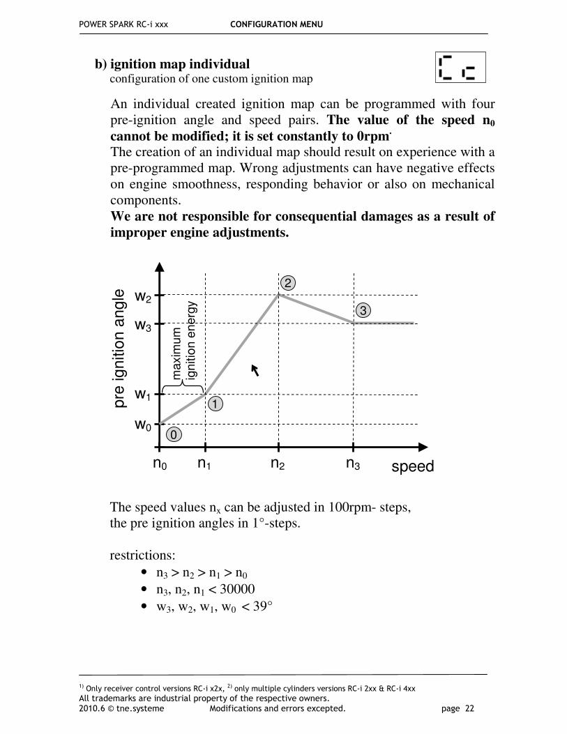
b) ignition map individual configuration of one custom ignition map
An individual created ignition map can be programmed with four pre-ignition angle and speed pairs. The value of the speed n0
cannot be modified; it is set constantly to 0rpm.
The creation of an individual map should result on experience with a pre-programmed map. Wrong adjustments can have negative effects on engine smoothness, responding behavior or also on mechanical components. We are not responsible for consequential damages as a result of
improper engine adjustments.
The speed values nx can be adjusted in 100rpm- steps, the pre ignition angles in 1°-steps. restrictions:
• n3 > n2 > n1 > n0
• n3, n2, n1 < 30000
• w3, w2, w1, w0 < 39°
speed n0 n1 n2 n3
w0
w1
w3
w2
pre
ig
nitio
n a
ngle
0
1
2
3
maxim
um
ig
nitio
n e
nerg
y

POWER SPARK RC-i xxx CONFIGURATION MENU
1) Only receiver control versions RC-i x2x, 2) only multiple cylinders versions RC-i 2xx & RC-i 4xx
All trademarks are industrial property of the respective owners. 2010.6 © tne.systeme Modifications and errors excepted. page 23
Adjustment of the custom ignition map
The adjustment of the custom ignition map is basically more complex than other menu adjustments. Before starting, please collect experience with the operation concept in other menu adjustments. Change primarily only few parameters and check the adjusted values, possibly note the values down. In the following example the current ignition angle and speed pairs shall be unchanged, only angle w0 shall be changed to 13° and speed n2 to 21500 rpm.
nr. action display
1-4 � select configuration menu
5 � wait until „Cc“ flashes
6 � actuate magnetic element
7 display shows the current speed values „n“ and the current angle values „°“ one after another n0 → w0 → n1 → w1 → n2 → w2 → n3 → w3
7a
The POWER SPARK has a two digit LED display. This is why the display of speed values occurs by sequentially displaying the figures. The display shows the speed figures one after another (here for example „n2“=12500rpm). display:
→ → → → →
7b
display of pre-ignition angle: (here for example „w2“=15°)
→

POWER SPARK RC-i xxx CONFIGURATION MENU
1) Only receiver control versions RC-i x2x, 2) only multiple cylinders versions RC-i 2xx & RC-i 4xx
All trademarks are industrial property of the respective owners. 2010.6 © tne.systeme Modifications and errors excepted. page 24
TIP
For a faster adjustment of the parameters the display of the values can be interrupted: � wait, until any angle will be displayed (for example „w0“) � actuate magnetic element
8 display shows „i i“, an information, that the proper programming can start and inputs from the user are expected
9 adjustable parameters flash one after another for 3sec: w0 → n1 → w1 → n2 → w2 → n3 → w3
10 � actuate magnetic element to select the parameter for modifying. Example: the angle „w0“ is selected for modifying
11 adjustable values of the tens flash one after another for 3 sec (0-3)
12 � wait until the desired figure flashes (for example „1“) � actuate magnetic element
13 adjustable values of the unit position flash one after another for 3 sec (0-9)
14 � wait until the desired figure flashes (for example „3“) � actuate magnetic element
15 the remaining adjustable parameters flash one after another for 3 sec: n1 → w1 → n2 → w2 → n3 → w3
16 � actuate magnetic element to select the parameter for modifying. Example: the speed „n2“ is selected for modifying
17 adjustable values of the ten thousands flash one after another for 3sec (0-2)
18 � wait until the desired figure flashes (for example „2“) � actuate magnetic element

POWER SPARK RC-i xxx CONFIGURATION MENU
1) Only receiver control versions RC-i x2x, 2) only multiple cylinders versions RC-i 2xx & RC-i 4xx
All trademarks are industrial property of the respective owners. 2010.6 © tne.systeme Modifications and errors excepted. page 25
Please note: After changing a parameter of the individual ignition map the individual map must be activated again.
• Therefore, select the ignition map menu „C-“ and adjust individual map „C0“. (see page 20)
19 adjustable values of the thousands flash one after another for 3sec (0-9)
20 � wait until the desired figure flashes (for example „1“) � actuate magnetic element
21 adjustable values of the hundreds flash one after another for 3sec (0-9)
22 � wait until the desired figure flashes (for example „5“) � actuate magnetic element
23 the remaining adjustable parameters flash one after another for 3sec: w2 → n3 → w3
24 � wait until w3 had flashed
25a The error message „EE“ will be shown if wrong values are entered. The values before modification are retained.
25b
display shows the new (or retained) speed values „n“ and angle values „°“ one after another n0 → w0 → n1 → w1 → n2 → w2 → n3 → w3
(also described in (7))
26 If all values are entered correctly and the described requirements are fulfilled, the values will be stored. Display indicates that the new values are stored.
27 POWER SPARK returns to the normal operation mode (display of engine speed and ignition standby)
!

POWER SPARK RC-i xxx CONFIGURATION MENU
1) Only receiver control versions RC-i x2x, 2) only multiple cylinders versions RC-i 2xx & RC-i 4xx
All trademarks are industrial property of the respective owners. 2010.6 © tne.systeme Modifications and errors excepted. page 26
c) Speed limit adjustment of engine speed limit (engine splutters) (factory setting: nL=<59900rpm>)
The engine can be protected against too high speeds with adjusting a speed limit. If the engine speed exceeds the adjusted speed limit for at least 0,4sec the ignition will be interrupted, the engine splutters. The speed limit can be adjusted exactly to 100rpm. If this safety function is not needed a speed limit value higher than the maximum engine speed should be programmed.
For example: speed limit of „21500 rpm“ shall be adjusted
nr. action display
1-4 � select configuration menu
5 � wait until „nL“ flashes
6 � actuate magnetic element
7
display shows the current speed limit by displaying the figures of the speed one after another. display scheme see section b) point 7a) (for example 2→0→0→0→0)
8 display shows „i i“, an information, that the proper programming can start and inputs from the user are expected
9 adjustable values of the ten thousands flash one after another for 3 sec (0-5)
10 � wait until the desired figure flashes (for example „2“) � actuate magnetic element
11 adjustable values of the thousands flash one after another for 3sec (0-9)
12 � wait until the desired figure flashes (for example „1“) � actuate magnetic element

POWER SPARK RC-i xxx CONFIGURATION MENU
1) Only receiver control versions RC-i x2x, 2) only multiple cylinders versions RC-i 2xx & RC-i 4xx
All trademarks are industrial property of the respective owners. 2010.6 © tne.systeme Modifications and errors excepted. page 27
13 adjustable values of the hundreds flash one after another for 3sec (0-9)
14 � wait until the desired figure flashes (for example „5“) � actuate magnetic element
15 for confirmation the adjusted speed is shown
16 display shows the new speed limit by displaying the figures of the speed one after another (for example 2→1→5→0→0)
17 Display indicates that the new values are stored
18 POWER SPARK returns to the normal operation mode. (display of engine speed and ignition standby)

POWER SPARK RC-i xxx CONFIGURATION MENU
1) Only receiver control versions RC-i x2x, 2) only multiple cylinders versions RC-i 2xx & RC-i 4xx
All trademarks are industrial property of the respective owners. 2010.6 © tne.systeme Modifications and errors excepted. page 28
d) Ignition energy selection of ignition energy (<2>)
The ignition energy of the POWER SPARK can be adapted to the engine. The stronger the spark is the safer is the ignition of the air fuel mixture; however the POWER SPARK consumes more electric power. To extend the operating time of the battery the ignition energy should be chosen not higher than needed for a smooth engine running. To improve the startup behavior the highest ignition energy is used between speed n0 and n1.
Adjustment possibilities:
• setting „1“ low ignition energy
• setting „2“ medium ignition energy (factory setting)
• setting „3“ high ignition energy
nr. action display
1-4 � select configuration menu
5 � wait until „IE“ flashes
6 � actuate magnetic element
7 display shows the current ignition energy (for example „2“)
8 adjustable values flash one after another for 3 sec (1-3)
9 � wait until the desired value flashes, (for example „3“) � actuate magnetic element
10 display shows the new selected ignition energy (here „3“)
11 display indicates that the new value is stored
12 POWER SPARK returns to the normal operation mode (display of engine speed and ignition standby)

POWER SPARK RC-i xxx CONFIGURATION MENU
1) Only receiver control versions RC-i x2x, 2) only multiple cylinders versions RC-i 2xx & RC-i 4xx
All trademarks are industrial property of the respective owners. 2010.6 © tne.systeme Modifications and errors excepted. page 29
e) Sensor angle compensation of mechanical displacement of speed sensor (<75>)
A small angular offset between the ideal trigger of the speed sensor (75° before top dead center) and the current value can be adjusted by setting the actual angle value between the speed sensor and the sensor magnet.
• Mark the angle between the trigger point of the speed sensor and the top dead center using menu „CS“ (see next page).
If you adjust angle values less than the nominal 75° the available computing time of the microcontroller will be shorter. For example, an adjustment of the sensor angle to 70° limits the use of high pre-ignition angles (≈35°) to engine speeds (<26500rpm).
nr. action display
1-4 � select configuration menu
5 � wait until „SA“ flashes
6 � actuate magnetic element
7 display shows the current sensor angle value (for example „75“)
8
adjustable values of the tens flash one after another for 3 sec (4-7) � wait until the desired figure flashes (for example „6“) � actuate magnetic element
9
adjustable values of the unit position flash one after another for 3 sec (4-7) � wait until the desired figure flashes (for example „6“) � actuate magnetic element
10 display shows the new selected angle value (here: 69)
11 display indicates that the new value is stored
12 POWER SPARK returns to the normal operation mode (display of engine speed and ignition standby)
!

POWER SPARK RC-i xxx CONFIGURATION MENU
1) Only receiver control versions RC-i x2x, 2) only multiple cylinders versions RC-i 2xx & RC-i 4xx
All trademarks are industrial property of the respective owners. 2010.6 © tne.systeme Modifications and errors excepted. page 30
f) Check sensor check mechanical position of speed sensor
The speed sensor has to be positioned in a way that it is triggered by the sensor magnet 75° before reaching the top dead center. With the help of this menu the adjustment can be done easily. => see also page 7 and page 29
If there is no further mechanical correction possible: o measure the actual triggering angle (for example mark
flywheel at the triggering point and at the top dead center with a pen and measure this angle).
o adjust the angle value in menu point „SA“ (page 29)
Important: Please note the constraints when adjusting the value of the sensor angle!
nr. action display
1-4 � select configuration menu
5 � wait until „CS“ flashes � actuate magnetic element
6 display shows permanently the first decimal point
7
� turn flywheel in direction of rotation until the display shows „ii“ The sensor magnet of the flywheel is detected by speed sensor.
8 � turn back flywheel until only the first decimal point is shown
9 � repeat step 7 to proceed in this way; adjust an angle of 75 ° between top dead center and trigger point.
10 after making the adjustment: � actuate magnetic element
11 POWER SPARK returns to normal operation mode (display of engine speed and ignition standby)

POWER SPARK RC-i xxx CONFIGURATION MENU
1) Only receiver control versions RC-i x2x, 2) only multiple cylinders versions RC-i 2xx & RC-i 4xx
All trademarks are industrial property of the respective owners. 2010.6 © tne.systeme Modifications and errors excepted. page 31
g) Factory reset reset POWER SPARK to default settings
The POWER SPARK can be reset in the initial state with default values at any time. WARNING: all stored settings get lost.
� The next page shows the values of the default setting.
nr. action display
1-4 � select configuration menu
5 � wait until „Fr“ flashes
6 � actuate magnetic element
7 „Fr“ flashes again for 3sec
8 � within this time actuate magnetic element
9 „Fr“ flashes again for 3sec
10 � within this time actuate magnetic element
11 display confirms the initialization with the factory settings
12 display indicates that the values are stored
13 POWER SPARK returns to the normal operation mode (display of engine speed and ignition standby)
14 � reset POWER SPARK, therefore disconnect and reconnect power supply
!

POWER SPARK RC-i xxx CONFIGURATION MENU
1) Only receiver control versions RC-i x2x, 2) only multiple cylinders versions RC-i 2xx & RC-i 4xx
All trademarks are industrial property of the respective owners. 2010.6 © tne.systeme Modifications and errors excepted. page 32
default setting
main menu menu parameter value
ignition map
1
(0-9)
configuration menu
individual ignition map values of map 1
sensor angle 75
(40..99)
engine speed limit 59900
(0-59900)
ignition energy 2
(1-3)
1)
receiver signal supervision1)
no (no, 0..99)
diagnostic menu 1)
warn threshold low voltage
receiver battery1)
no (no, 2..9,9)
1)
shutdown threshold low voltage
receiver battery1)
no (no, 2..9,9)
warn threshold low voltage
main battery
no (no, 4..9,9)
shutdown threshold low voltage main battery
no (no, 4..9,9)

POWER SPARK RC-i xxx STATUS MENU
1) Only receiver control versions RC-i x2x, 2) only multiple cylinders versions RC-i 2xx & RC-i 4xx
All trademarks are industrial property of the respective owners. 2010.6 © tne.systeme Modifications and errors excepted. page 33
STATUS MENU
The status menu can only be selected when the engine halts. It includes the menu items:
a) maximum engine speed „nh“
display of maximum achieved engine speed
b) voltage of main battery „Ub“ display of actual main battery voltage
c) voltage of receiver battery1)
„Ur“ display of actual receiver battery voltage
selection of status menu
a) Display of maximum achieved engine speed „nh“ (n highest)
=> value will be erased when removing the power supply => value is averaged over a period of 0.8sec
nr. action display
1 POWER SPARK in normal operation mode
2 � actuate magnetic element (by approaching the programming magnet to the housing near the magnet sensitive element)
3 after 3sec the right figure „d“ flashes � wait 3 sec to get to the status menu
4 the selectable menu items flash one after the other for 3sec in the order: „nh“ → „Ub“ → „Ur“1)
nr. action display
1-4 � select status menu
5 � wait until „nh“ flashes � actuate magnetic element

POWER SPARK RC-i xxx STATUS MENU
1) Only receiver control versions RC-i x2x, 2) only multiple cylinders versions RC-i 2xx & RC-i 4xx
All trademarks are industrial property of the respective owners. 2010.6 © tne.systeme Modifications and errors excepted. page 34
b) Display of actual main battery voltage „Ub“ (U battery)
c) Display of actual receiver battery voltage1)
„Ur“
(U receiver)
6 display shows the figures of speed one after another (for example 2→5→6→5→4)
7 POWER SPARK returns to the normal operation mode (display of engine speed and ignition standby)
nr. action display
1-4 � select status menu
5 � wait until „Ub“ flashes � actuate magnetic element
6 display shows the actual battery voltage (for example 5,6 vVolt)
7 POWER SPARK returns to the normal operation mode (display of engine speed and ignition standby)
nr. action display
1-4 � select status menu
5 � wait until „Ur“ flashes �actuate magnetic element
6 display shows the actual receiver battery voltage (for example 4,9 volt)
7 POWER SPARK returns to the normal operation mode (display of engine speed and ignition standby)

POWER SPARK RC-i xxx DIAGNOSTICS MENU
1) Only receiver control versions RC-i x2x, 2) only multiple cylinders versions RC-i 2xx & RC-i 4xx
All trademarks are industrial property of the respective owners. 2010.6 © tne.systeme Modifications and errors excepted. page 35
DIAGNOSTICS MENU
General
The POWER SPARK provides several diagnostic functions to increase the reliability of the system.
• If the monitored voltage falls below the adjusted warning threshold ignition failures will be systematically generated starting from the
half maximum allowed engine speed. (=> engine splutters) to inform the user of a weak battery. (adjustment of speed in menu item „nl“, p.26)
• If the monitored voltage falls below the switch-off threshold the engine will be shut down for safety. (for example cable break of power supply on the RC-receiver)
• When receiving an illegal signal from the RC-receiver the engine will be shut down
1). (f.e. in case of failure of radio transmission)
A warning or shutdown is only triggered after a defined time (see table on page 37) when the monitored parameters have exceeded or under-run the permissible range of values. The warning or shutdown criteria are explained in the respective menus descriptions. The diagnostic menu can only be selected when the engine halts. It includes the menu items:
a) Supervision of receiver signal1)
� engine shutdown
activation and adjustment of the valid receiver signal range
b) Warning threshold receiver battery1)
� engine splutters at nL/2
activation and adjustment of warning threshold for supervision of receiver battery voltage
c) Shutdown threshold receiver battery1
� engine shutdown activation and adjustment of shutdown threshold for supervision of receiver battery voltage
d) Warning threshold main battery � engine splutters at nL/2
activation and adjustment of warning threshold for supervision of main battery voltage
e) Shutdown threshold main battery � engine shutdown activation and adjustment of shutdown threshold for supervision of main battery voltage

POWER SPARK RC-i xxx DIAGNOSTICS MENU
1) Only receiver control versions RC-i x2x, 2) only multiple cylinders versions RC-i 2xx & RC-i 4xx
All trademarks are industrial property of the respective owners. 2010.6 © tne.systeme Modifications and errors excepted. page 36
selection of diagnostic menu
nr. action display
1 POWER SPARK in normal operation mode
2
� actuate magnetic element (by approaching the programming magnet to the housing near the magnet sensitive element, remove after display shows “. .”)
3 after 3sec the right figure „d“ flashes
3b
during this time: � actuate magnetic element (by approaching the programming magnet to the housing near the magnet sensitive element, remove after display shows “. .”)
4 Diagnostic menu will be selected

POWER SPARK RC-i xxx DIAGNOSTICS MENU
1) Only receiver control versions RC-i x2x, 2) only multiple cylinders versions RC-i 2xx & RC-i 4xx
All trademarks are industrial property of the respective owners. 2010.6 © tne.systeme Modifications and errors excepted. page 37
Shutdown criteria and display of diagnostic response
� The valid input values of the shutdown or warning thresholds and the receiver signal shows the table „ technical data“ (last page)
PLEASE NOTE:
• After triggering a diagnostic function (shutdown of engine) o the display shows the failure o the ignition is deactivated � to continue operation the voltage supply of the POWER SPARK has to be interrupted and reapplied (reset)
parameter condition result display
„rL“ receiver low1)
warn threshold receiver battery
battery voltage falls below warn threshold for minimum 5sec
engine splutters reaching half maximum allowed speed max. zuläss.
„rd“ receiver dead1)
shutdown threshold receiver battery
battery voltage falls below shutdown thres. for minimum 3sec
engine shutdown
„bL“ battery low warn threshold main battery
battery voltage falls below warn threshold for minimum 5sec
engine splutters reaching half maximum allowed speed halben max.
„bd“ battery dead shutdown threshold
main battery
battery voltage falls below shutdown thres. for minimum 5sec
engine shutdown
„rS“ receiver
signal1)
supervision of receiver signal
receiver signal out of the adjusted range for minimum 2sec
engine shutdown
!

POWER SPARK RC-i xxx DIAGNOSTICS MENU
1) Only receiver control versions RC-i x2x, 2) only multiple cylinders versions RC-i 2xx & RC-i 4xx
All trademarks are industrial property of the respective owners. 2010.6 © tne.systeme Modifications and errors excepted. page 38
a) Supervision of receiver signal1)
activation and adjustment of the valid receiver signal range
The POWER SPARK can monitor the signal of a radio-control receiver. If the received signal is above or below the adjusted threshold values for more than 2 sec. the engine is shut down.
An appropriate signal for the supervision can be the „gas“-signal (to accelerate / slow down (reverse)). Alternatively any signal can be used (for example steering signal) or a signal that is exclusively reserved for supervision / shutdown.
sequence of programming: The POWER SPARK displays the adjusted values, afterwards it displays the actual measured value of the receiver signal for 10 seconds. Following the thresholds can be modified; in the last step the new values are confirmed. Within this time window the display shows the actual signal value of the receiver. The nominal receiver signal range can be determined by moving the gas-poti at the remote control. To avoid an unintended shutdown of the engine caused by this diagnostic function a tolerance up to about 5-10% should be added (respectively subtracted) to the nominal values. In the following example a signal range from „28“ – „73“ was determined. To avoid an unintended shutdown of the POWER SPARK, a tolerance value was added to the upper signal value respectively subtracted from the lower signal value. => The thresholds „25“ and „78“ have been chosen.
0
28
100
73
78 25
receiver signal measured signal range
signal range + tolerance
-3 +5
POWER SPARK RC-i xxx DIAGNOSTICS MENU
1) Only receiver control versions RC-i x2x, 2) only multiple cylinders versions RC-i 2xx & RC-i 4xx
All trademarks are industrial property of the respective owners. 2010.6 © tne.systeme Modifications and errors excepted. page 39
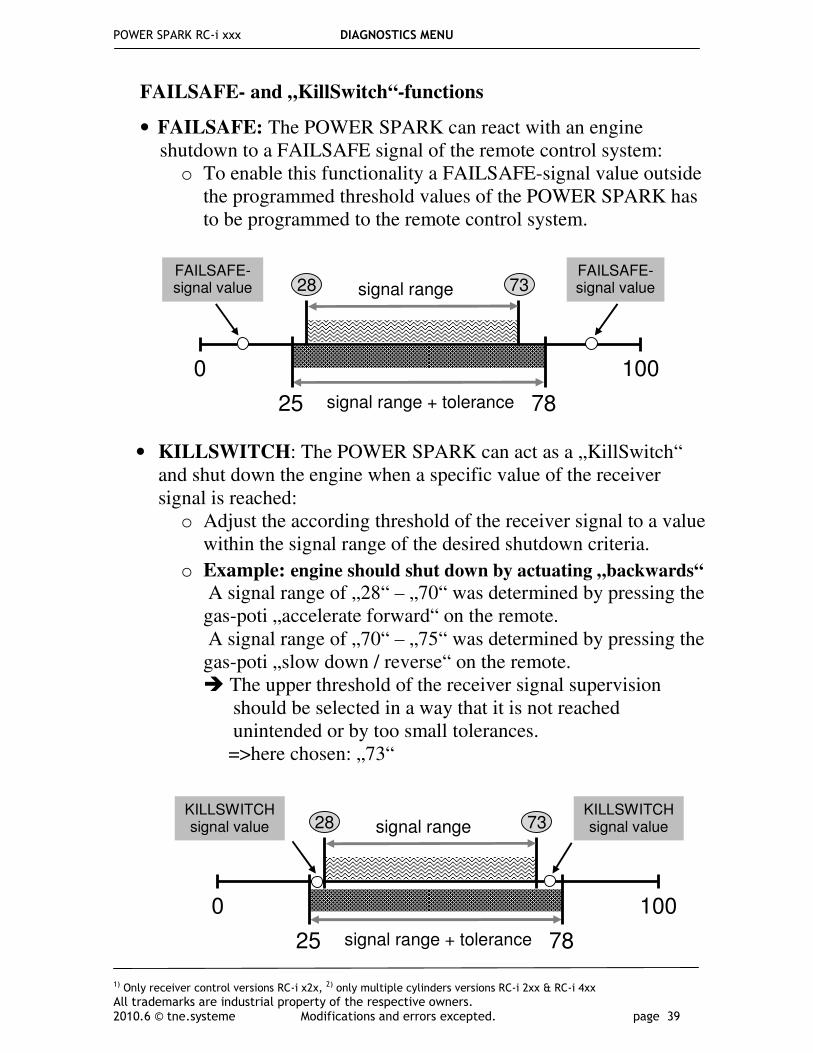
FAILSAFE- and „KillSwitch“-functions
• FAILSAFE: The POWER SPARK can react with an engine shutdown to a FAILSAFE signal of the remote control system:
o To enable this functionality a FAILSAFE-signal value outside the programmed threshold values of the POWER SPARK has to be programmed to the remote control system.
• KILLSWITCH: The POWER SPARK can act as a „KillSwitch“ and shut down the engine when a specific value of the receiver signal is reached: o Adjust the according threshold of the receiver signal to a value
within the signal range of the desired shutdown criteria.
o Example: engine should shut down by actuating „backwards“
A signal range of „28“ – „70“ was determined by pressing the gas-poti „accelerate forward“ on the remote. A signal range of „70“ – „75“ was determined by pressing the gas-poti „slow down / reverse“ on the remote. � The upper threshold of the receiver signal supervision should be selected in a way that it is not reached unintended or by too small tolerances. =>here chosen: „73“
0
28
100
73
78 25
signal range
signal range + tolerance
KILLSWITCH signal value
KILLSWITCH signal value
0
28
100
73
78 25
signal range
signal range + tolerance
FAILSAFE-signal value
FAILSAFE-signal value
POWER SPARK RC-i xxx DIAGNOSTICS MENU
1) Only receiver control versions RC-i x2x, 2) only multiple cylinders versions RC-i 2xx & RC-i 4xx
All trademarks are industrial property of the respective owners. 2010.6 © tne.systeme Modifications and errors excepted. page 40
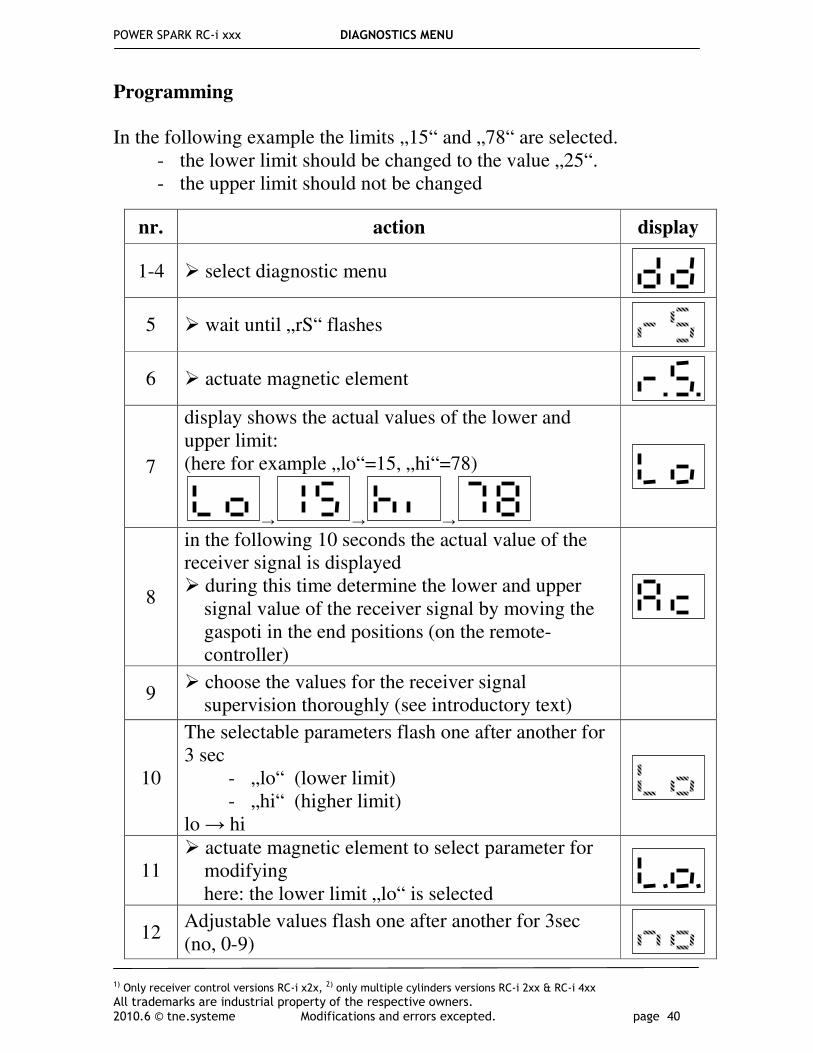
Programming
In the following example the limits „15“ and „78“ are selected.
- the lower limit should be changed to the value „25“. - the upper limit should not be changed
nr. action display
1-4 � select diagnostic menu
5 � wait until „rS“ flashes
6 � actuate magnetic element
7
display shows the actual values of the lower and upper limit: (here for example „lo“=15, „hi“=78)
→ → →
8
in the following 10 seconds the actual value of the receiver signal is displayed � during this time determine the lower and upper signal value of the receiver signal by moving the gaspoti in the end positions (on the remote- controller)
9 � choose the values for the receiver signal supervision thoroughly (see introductory text)
10
The selectable parameters flash one after another for 3 sec
- „lo“ (lower limit) - „hi“ (higher limit)
lo → hi
11 � actuate magnetic element to select parameter for modifying here: the lower limit „lo“ is selected
12 Adjustable values flash one after another for 3sec (no, 0-9)

POWER SPARK RC-i xxx DIAGNOSTICS MENU
1) Only receiver control versions RC-i x2x, 2) only multiple cylinders versions RC-i 2xx & RC-i 4xx
All trademarks are industrial property of the respective owners. 2010.6 © tne.systeme Modifications and errors excepted. page 41
PLEASE NOTE:
• To deactivate the receiver signal supervision o set the upper or lower threshold to „no“
• To activate the receiver signal supervision o set the upper and lower threshold to valid values
12a To disable this diagnostic function: � actuate magnetic element
12b
To enable this diagnostic function: � wait until the desired figure of the tens flashes (for example „2“) � actuate magnetic element
adjustable values of the unit position flash one after another for 3sec (0-9)
� wait until the desired figure flashes (for example „5“) � actuate magnetic element
13 The remaining selectable parameter (upper limit) „hi“ flashes for 3sec
13a if the upper limit „hi“ should be changed: � actuate magnetic element
� (input as described in point 12
13b if the upper limit „hi“ should not be changed: � wait until the new values are displayed (in this example)
14
display shows the new values of the lower and upper limit: (here for example „lo“=25, „hi“=78)
→ → →
15 Display indicates that the new values are stored.
16 POWER SPARK returns to the normal operation mode (display of engine speed and ignition standby)
17 � reset POWER SPARK, therefore disconnect and reconnect power supply
!

POWER SPARK RC-i xxx DIAGNOSTICS MENU
1) Only receiver control versions RC-i x2x, 2) only multiple cylinders versions RC-i 2xx & RC-i 4xx
All trademarks are industrial property of the respective owners. 2010.6 © tne.systeme Modifications and errors excepted. page 42
b) - e) Voltage monitoring activation and adjustment of warning or shutdown thresholds for supervision of main or receiver battery voltage
The following example shows exemplarily the deactivation / activation of the warning threshold for monitoring the voltage of the main battery. The adjustments of the other thresholds are identical.
nr. action display
1-4 � select diagnostic menu
5 � wait until „bl“ flashes
6 � actuate magnetic element
7 display shows actual voltage value (for example „4.5“)
8 adjustable values flash one after another for 3sec (no, 0-9)
8a To disable this diagnostic function: � actuate magnetic element
8b
To enable this diagnostic function: � wait until the desired figure of the tens flashes (for example „4“) � actuate magnetic element
9 � wait until the desired figure of the unit position flashes (for example „0“) � actuate magnetic element
10 display shows the new voltage values (here „4.0“)
11 Display indicates that the new value is stored
12 POWER SPARK returns to normal operation mode (display of engine speed and ignition standby)

POWER SPARK RC-i xxx
1) Only receiver control versions RC-i x2x, 2) only multiple cylinders versions RC-i 2xx & RC-i 4xx
All trademarks are industrial property of the respective owners. 2010.6 © tne.systeme Modifications and errors excepted. page 43
feature version
RC-i 1x0 RC-i 2x0 RC-i 4x0
number of cylinders 1 2 3 & 4
max. speed [rpm] 30000
accuracy of speed measurement +/- 1% (25°C)
power supply 4-12V3)
detectable pulse width of receiver signal1)
0,8 .. 2,2ms
min. signal level of receiver signal1)
1,6V
warn threshold for low voltage main battery
4..9,9V
shutdown threshold for low voltage main battery
4..9,9V
warn threshold for low voltage receiver battery
1)
2..9,9V
warn threshold for low voltage receiver battery1)
2..9,9V
reverse polarity protection with fuse 3A 5A 10A
current consumption: 4) energy 2: 6V
7500rpm 15000rpm
≈0,5A ≈1,0A
≈1,0A ≈2,0A
≈2,0A ≈4,1A
current consumption: 4) energy 2: 9V
7500rpm 15000rpm
≈0,4A ≈0,7A
≈0,7A ≈1,3 A
≈1,4A ≈2,7A
current consumption: 4) energy 2: 12V
15000rpm 30000rpm
≈0,5A ≈1,1A
≈1,1A ≈2,2A
≈2,2A ≈4,4A
dimensions [mm] (without flange) 82 x 42 82 x 42 82 x 82
dimensions [mm] (with flange) 110 x 42 110 x 42 110 x 82
height [mm] 18 18 18
hole pattern [mm] 100 x 32 100 x 32 100 x 72 100 x 36
weight [g] ~100 ~110 ~195
3) for multiple cylinders versions and high speed (>20000rpm) the supply should be min. 9V 4) current consumption has a strong dependency on ignition coil, spark plug an wiring cross section
Technical data