ELECTRONIC FUEL INJECTION -...
51
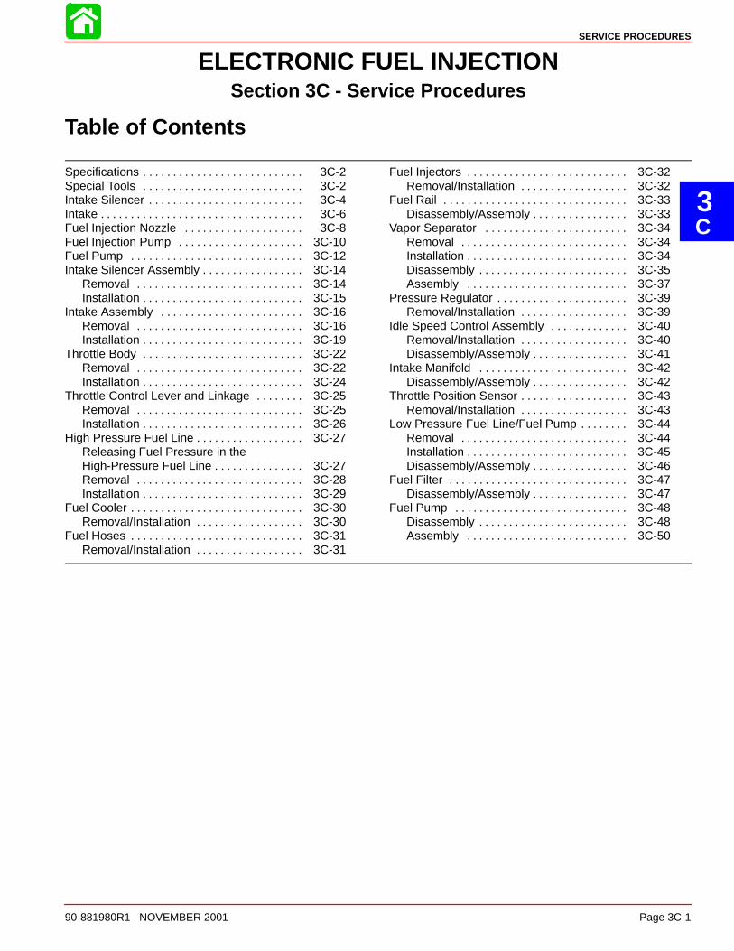
3 C SERVICE PROCEDURES 90-881980R1 NOVEMBER 2001 Page 3C-1 ELECTRONIC FUEL INJECTION Section 3C - Service Procedures Table of Contents Specifications 3C-2 . . . . . . . . . . . . . . . . . . . . . . . . . . . Special Tools 3C-2 . . . . . . . . . . . . . . . . . . . . . . . . . . . Intake Silencer 3C-4 . . . . . . . . . . . . . . . . . . . . . . . . . . Intake 3C-6 . . . . . . . . . . . . . . . . . . . . . . . . . . . . . . . . . . Fuel Injection Nozzle 3C-8 . . . . . . . . . . . . . . . . . . . . Fuel Injection Pump 3C-10 . . . . . . . . . . . . . . . . . . . . . Fuel Pump 3C-12 . . . . . . . . . . . . . . . . . . . . . . . . . . . . . Intake Silencer Assembly 3C-14 . . . . . . . . . . . . . . . . . Removal 3C-14 . . . . . . . . . . . . . . . . . . . . . . . . . . . . Installation 3C-15 . . . . . . . . . . . . . . . . . . . . . . . . . . . Intake Assembly 3C-16 . . . . . . . . . . . . . . . . . . . . . . . . Removal 3C-16 . . . . . . . . . . . . . . . . . . . . . . . . . . . . Installation 3C-19 . . . . . . . . . . . . . . . . . . . . . . . . . . . Throttle Body 3C-22 . . . . . . . . . . . . . . . . . . . . . . . . . . . Removal 3C-22 . . . . . . . . . . . . . . . . . . . . . . . . . . . . Installation 3C-24 . . . . . . . . . . . . . . . . . . . . . . . . . . . Throttle Control Lever and Linkage 3C-25 . . . . . . . . Removal 3C-25 . . . . . . . . . . . . . . . . . . . . . . . . . . . . Installation 3C-26 . . . . . . . . . . . . . . . . . . . . . . . . . . . High Pressure Fuel Line 3C-27 . . . . . . . . . . . . . . . . . . Releasing Fuel Pressure in the High-Pressure Fuel Line 3C-27 . . . . . . . . . . . . . . . Removal 3C-28 . . . . . . . . . . . . . . . . . . . . . . . . . . . . Installation 3C-29 . . . . . . . . . . . . . . . . . . . . . . . . . . . Fuel Cooler 3C-30 . . . . . . . . . . . . . . . . . . . . . . . . . . . . . Removal/Installation 3C-30 . . . . . . . . . . . . . . . . . . Fuel Hoses 3C-31 . . . . . . . . . . . . . . . . . . . . . . . . . . . . . Removal/Installation 3C-31 . . . . . . . . . . . . . . . . . . Fuel Injectors 3C-32 . . . . . . . . . . . . . . . . . . . . . . . . . . . Removal/Installation 3C-32 . . . . . . . . . . . . . . . . . . Fuel Rail 3C-33 . . . . . . . . . . . . . . . . . . . . . . . . . . . . . . . Disassembly/Assembly 3C-33 . . . . . . . . . . . . . . . . Vapor Separator 3C-34 . . . . . . . . . . . . . . . . . . . . . . . . Removal 3C-34 . . . . . . . . . . . . . . . . . . . . . . . . . . . . Installation 3C-34 . . . . . . . . . . . . . . . . . . . . . . . . . . . Disassembly 3C-35 . . . . . . . . . . . . . . . . . . . . . . . . . Assembly 3C-37 . . . . . . . . . . . . . . . . . . . . . . . . . . . Pressure Regulator 3C-39 . . . . . . . . . . . . . . . . . . . . . . Removal/Installation 3C-39 . . . . . . . . . . . . . . . . . . Idle Speed Control Assembly 3C-40 . . . . . . . . . . . . . Removal/Installation 3C-40 . . . . . . . . . . . . . . . . . . Disassembly/Assembly 3C-41 . . . . . . . . . . . . . . . . Intake Manifold 3C-42 . . . . . . . . . . . . . . . . . . . . . . . . . Disassembly/Assembly 3C-42 . . . . . . . . . . . . . . . . Throttle Position Sensor 3C-43 . . . . . . . . . . . . . . . . . . Removal/Installation 3C-43 . . . . . . . . . . . . . . . . . . Low Pressure Fuel Line/Fuel Pump 3C-44 . . . . . . . . Removal 3C-44 . . . . . . . . . . . . . . . . . . . . . . . . . . . . Installation 3C-45 . . . . . . . . . . . . . . . . . . . . . . . . . . . Disassembly/Assembly 3C-46 . . . . . . . . . . . . . . . . Fuel Filter 3C-47 . . . . . . . . . . . . . . . . . . . . . . . . . . . . . . Disassembly/Assembly 3C-47 . . . . . . . . . . . . . . . . Fuel Pump 3C-48 . . . . . . . . . . . . . . . . . . . . . . . . . . . . . Disassembly 3C-48 . . . . . . . . . . . . . . . . . . . . . . . . . Assembly 3C-50 . . . . . . . . . . . . . . . . . . . . . . . . . . .
Transcript of ELECTRONIC FUEL INJECTION -...
3C
SERVICE PROCEDURES
90-881980R1 NOVEMBER 2001 Page 3C-1
ELECTRONIC FUEL INJECTIONSection 3C - Service Procedures
Table of Contents
Specifications 3C-2. . . . . . . . . . . . . . . . . . . . . . . . . . . Special Tools 3C-2. . . . . . . . . . . . . . . . . . . . . . . . . . . Intake Silencer 3C-4. . . . . . . . . . . . . . . . . . . . . . . . . . Intake 3C-6. . . . . . . . . . . . . . . . . . . . . . . . . . . . . . . . . . Fuel Injection Nozzle 3C-8. . . . . . . . . . . . . . . . . . . . Fuel Injection Pump 3C-10. . . . . . . . . . . . . . . . . . . . . Fuel Pump 3C-12. . . . . . . . . . . . . . . . . . . . . . . . . . . . . Intake Silencer Assembly 3C-14. . . . . . . . . . . . . . . . .
Removal 3C-14. . . . . . . . . . . . . . . . . . . . . . . . . . . . Installation 3C-15. . . . . . . . . . . . . . . . . . . . . . . . . . .
Intake Assembly 3C-16. . . . . . . . . . . . . . . . . . . . . . . . Removal 3C-16. . . . . . . . . . . . . . . . . . . . . . . . . . . . Installation 3C-19. . . . . . . . . . . . . . . . . . . . . . . . . . .
Throttle Body 3C-22. . . . . . . . . . . . . . . . . . . . . . . . . . . Removal 3C-22. . . . . . . . . . . . . . . . . . . . . . . . . . . . Installation 3C-24. . . . . . . . . . . . . . . . . . . . . . . . . . .
Throttle Control Lever and Linkage 3C-25. . . . . . . . Removal 3C-25. . . . . . . . . . . . . . . . . . . . . . . . . . . . Installation 3C-26. . . . . . . . . . . . . . . . . . . . . . . . . . .
High Pressure Fuel Line 3C-27. . . . . . . . . . . . . . . . . . Releasing Fuel Pressure in theHigh-Pressure Fuel Line 3C-27. . . . . . . . . . . . . . . Removal 3C-28. . . . . . . . . . . . . . . . . . . . . . . . . . . . Installation 3C-29. . . . . . . . . . . . . . . . . . . . . . . . . . .
Fuel Cooler 3C-30. . . . . . . . . . . . . . . . . . . . . . . . . . . . . Removal/Installation 3C-30. . . . . . . . . . . . . . . . . .
Fuel Hoses 3C-31. . . . . . . . . . . . . . . . . . . . . . . . . . . . . Removal/Installation 3C-31. . . . . . . . . . . . . . . . . .
Fuel Injectors 3C-32. . . . . . . . . . . . . . . . . . . . . . . . . . . Removal/Installation 3C-32. . . . . . . . . . . . . . . . . .
Fuel Rail 3C-33. . . . . . . . . . . . . . . . . . . . . . . . . . . . . . . Disassembly/Assembly 3C-33. . . . . . . . . . . . . . . .
Vapor Separator 3C-34. . . . . . . . . . . . . . . . . . . . . . . . Removal 3C-34. . . . . . . . . . . . . . . . . . . . . . . . . . . . Installation 3C-34. . . . . . . . . . . . . . . . . . . . . . . . . . . Disassembly 3C-35. . . . . . . . . . . . . . . . . . . . . . . . . Assembly 3C-37. . . . . . . . . . . . . . . . . . . . . . . . . . .
Pressure Regulator 3C-39. . . . . . . . . . . . . . . . . . . . . . Removal/Installation 3C-39. . . . . . . . . . . . . . . . . .
Idle Speed Control Assembly 3C-40. . . . . . . . . . . . . Removal/Installation 3C-40. . . . . . . . . . . . . . . . . . Disassembly/Assembly 3C-41. . . . . . . . . . . . . . . .
Intake Manifold 3C-42. . . . . . . . . . . . . . . . . . . . . . . . . Disassembly/Assembly 3C-42. . . . . . . . . . . . . . . .
Throttle Position Sensor 3C-43. . . . . . . . . . . . . . . . . . Removal/Installation 3C-43. . . . . . . . . . . . . . . . . .
Low Pressure Fuel Line/Fuel Pump 3C-44. . . . . . . . Removal 3C-44. . . . . . . . . . . . . . . . . . . . . . . . . . . . Installation 3C-45. . . . . . . . . . . . . . . . . . . . . . . . . . . Disassembly/Assembly 3C-46. . . . . . . . . . . . . . . .
Fuel Filter 3C-47. . . . . . . . . . . . . . . . . . . . . . . . . . . . . . Disassembly/Assembly 3C-47. . . . . . . . . . . . . . . .
Fuel Pump 3C-48. . . . . . . . . . . . . . . . . . . . . . . . . . . . . Disassembly 3C-48. . . . . . . . . . . . . . . . . . . . . . . . . Assembly 3C-50. . . . . . . . . . . . . . . . . . . . . . . . . . .

SERVICE PROCEDURES
Page 3C-2 90-881980R1 NOVEMBER 2001
Specifications
FUELSYSTEM
Fuel Pump TypeFuel Pump:
Discharge (@ 3000 rpm)Pressure (Maximum)
Plunger StrokeFuel Tank Capacity
External (Plunger/Diaphragm)
17 gph (65 L/h)7 psi (49 kPa)
0.23 - 0.36 in. (5.85 - 9.05 mm)Accessory
FUEL INJECTION
Fuel Injection SystemIdle rpm (In Neutral) WarmIdle rpm (In Forward Gear) WarmFuel Pressure @ Rail
Batch (1 & 4) - (2 & 3)750 ± 50 rpm700 ± 50 rpm
43.5 psi (300 kPa)
Special Tools
1. Fuel Pressure Gauge 91-16850A7 or Fuel Pressure Gauge 91-852087A3.
5179691-16850A7
91-852087A3
2. Tamper proof screw torx bit set p/n 91-881828.

SERVICE PROCEDURES
90-881980R1 NOVEMBER 2001 Page 3C-3
Notes:

SERVICE PROCEDURES
Page 3C-4 90-881980R1 NOVEMBER 2001
INTAKE SILENCER
16
17
1312
20
203
3
19
12
9
1011
21
56
18
1415
1615
8 78
8 7 84

SERVICE PROCEDURES
90-881980R1 NOVEMBER 2001 Page 3C-5
INTAKE SILENCER
REFTORQUE
REF.NO. QTY. DESCRIPTION lb. in. lb.ft. Nm
1 1 INTAKE SILENCER2 1 INTAKE AIR TEMPERATURE SENSOR3 4 O-RING4 6 BOLT (M6 X 16 MM) 70 7.95 2 BOLT (M8 X 20 MM) 13 186 1 BRACKET7 2 BRACKET
8 8 BOLT (M6 X 20 MM) 70 7.99 1 INDUCTION SILENCER10 1 MOUNTING BRACKET11 1 SCREW (M6 X 20 MM) 70 7.912 2 PIN13 1 GASKET
14 1 BREATHER PIPE15 2 CLAMP16 2 BOLT (M6 X 12 MM) 70 7.917 1 CLIP18 1 CLAMP19 2 BOLT (M6 X 105 MM) 70 7.920 5 BOLT (M8 X 40 MM) 13 18
21 1 SCREEN

SERVICE PROCEDURES
Page 3C-6 90-881980R1 NOVEMBER 2001
INTAKE
23
22
2021
349
933
27262928 35
32
31
25
1
30
2
32
43
1819
24
10
1211
12
13
6
5
98
7
98
16 1715
17

SERVICE PROCEDURES
90-881980R1 NOVEMBER 2001 Page 3C-7
INTAKE
REFTORQUE
REF.NO. QTY. DESCRIPTION lb. in. lb.ft. Nm
1 1 MANIFOLD2 4 O-RING3 4 DOWEL PIN4 3 BOLT5 1 THROTTLE BODY6 1 SPRING7 2 SCREW
8 6 BOLT (M8 X 70 MM) 13 189 9 WASHER10 1 THROTTLE BODY11 1 SCREW12 2 SPRING13 1 SCREW
14 2 SCREW15 1 LINK JOINT16 1 LINK JOINT17 1 NUT18 1 THROTTLE POSITION SENSOR19 1 O-RING20 2 SCREW (M5 X 15 MM) 43 5
21 2 WASHER22 1 BRACKET23 3 SCREW (TAMPERPROOF) 40 4.524 1 HOSE– 1 CONTROL VALVE ASSEMBLY25 1 BODY26 1 CONTROL VALVE
27 1 O-RING28 3 SCREW (M4 X 12 MM) 18 229 3 WASHER30 1 FILTER31 1 MAP SENSOR32 2 SCREW (M5 X 6 MM) 43 533 1 BOLT (M6 X 24 MM) 70 7.9
34 2 BOLT (M6 X 60 MM) 70 7.935 1 WIRE HARNESS

SERVICE PROCEDURES
Page 3C-8 90-881980R1 NOVEMBER 2001
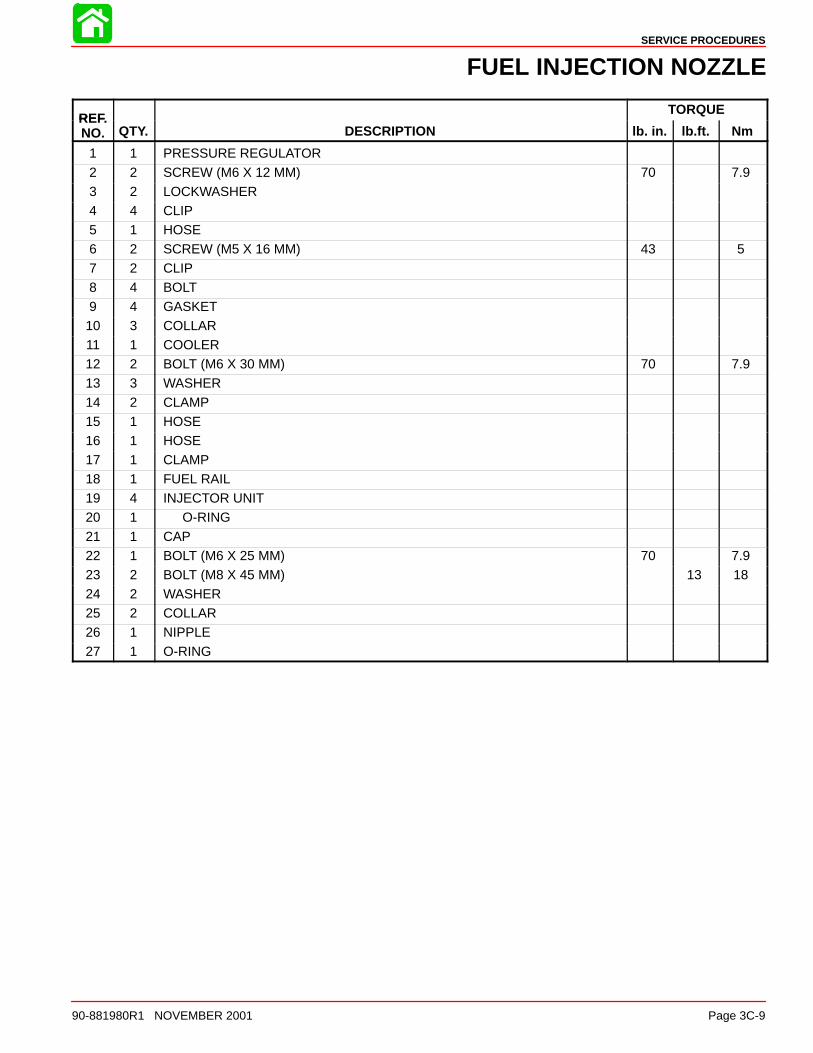
FUEL INJECTION NOZZLE
1
2 3
4
5
9 8
4 7
21
1013 22
2324
18
24 23
26
6
27
25
15
14
7
1213
2019
14
11
25
121310
9 89 8
10
9 8
44
1617
SERVICE PROCEDURES
90-881980R1 NOVEMBER 2001 Page 3C-9
FUEL INJECTION NOZZLE
REFTORQUE
REF.NO. QTY. DESCRIPTION lb. in. lb.ft. Nm
1 1 PRESSURE REGULATOR2 2 SCREW (M6 X 12 MM) 70 7.93 2 LOCKWASHER4 4 CLIP5 1 HOSE6 2 SCREW (M5 X 16 MM) 43 57 2 CLIP
8 4 BOLT9 4 GASKET10 3 COLLAR11 1 COOLER12 2 BOLT (M6 X 30 MM) 70 7.913 3 WASHER
14 2 CLAMP15 1 HOSE16 1 HOSE17 1 CLAMP18 1 FUEL RAIL19 4 INJECTOR UNIT20 1 O-RING
21 1 CAP22 1 BOLT (M6 X 25 MM) 70 7.923 2 BOLT (M8 X 45 MM) 13 1824 2 WASHER25 2 COLLAR26 1 NIPPLE27 1 O-RING

SERVICE PROCEDURES
Page 3C-10 90-881980R1 NOVEMBER 2001
FUEL INJECTION PUMP
A = To fitting in exhaust plate
30
2222
23
21
20
1112
13
14
15 564
16
17
10
1
1919 18
31
3231
20
20
2829
2020
27
27
2327
23
27
23
27
27
2624
23
25
A
32
7
8
9

SERVICE PROCEDURES
90-881980R1 NOVEMBER 2001 Page 3C-11
FUEL INJECTION PUMP
REFTORQUE
REF.NO. QTY. DESCRIPTION lb. in. lb.ft. Nm
– 1 VAPOR SEPARATOR1 1 COVER2 1 VALVE SEAT3 1 O-RING4 1 BODY5 1 FLOAT6 1 FLOAT PIN
7 1 NEEDLE VALVE8 1 PLATE9 1 SCREW (M3 X 8 MM)10 7 SCREW (M4 X 16 MM) 18 211 1 GASKET12 1 DAMPER
13 1 FUEL PUMP14 1 FILTER15 1 COVER16 1 DRAIN SCREW17 1 GASKET18 1 HOSE KIT19 2 CLIP
20 5 CLIP21 1 HOSE22 2 HOSE23 5 TEE24 1 HOSE25 1 HOSE26 1 HOSE
27 6 HOSE28 1 HOSE29 1 HOSE30 1 HOSE31 6 COLLAR32 3 DAMPER

SERVICE PROCEDURES
Page 3C-12 90-881980R1 NOVEMBER 2001
FUEL PUMP
1110
98
67
52
123
4
13
1 14
15
1614
18
19
21
22
23
2425
33
1720
25
3435
36
37
29
30
323132
28
2627
29

SERVICE PROCEDURES
90-881980R1 NOVEMBER 2001 Page 3C-13
FUEL PUMP
REFTORQUE
REF.NO. QTY. DESCRIPTION lb. in. lb.ft. Nm
1 1 FUEL PUMP2 1 BODY3 1 SPRING4 1 PLUNGER5 1 SPRING6 1 DIAPHRAGM7 1 PIN
8 1 BODY9 1 DIAPHRAGM10 1 BODY11 3 SCREW12 3 NUT13 1 O-RING
14 2 CLAMP15 2 BOLT (M6 X 30 MM) 70 7.916 1 HOSE17 1 BRACKET18 1 BOLT (M6 X 16 MM) 70 7.919 1 NUT 70 7.920 1 FILTER ASSEMBLY
21 1 CUP22 1 O-RING23 1 FLOAT24 1 ELEMENT25 2 CLAMP26 1 BRACKET27 2 BOLT (M7 X 48 MM) 150 17
28 2 DOWEL PIN29 2 WASHER30 1 FUEL CHANGE LEVER31 1 SHAFT32 2 PIN33 1 HOSE (55 IN.)34 1 STA-STRAP
35 1 CONNECTOR36 1 CAP37 1 CONDUIT

SERVICE PROCEDURES
Page 3C-14 90-881980R1 NOVEMBER 2001
Intake Silencer Assembly
Removal1. Remove access panel from port side bottom cowl.
a
a - Access Panel2. Disconnect the air temperature sensor connector.
3. Remove the following breather hoses: cylinder head to intake silencer, idle air controlassembly to intake silencer.
4. Remove mounting screws from intake silencer and mounting screw from induction si-lencer.
5. Remove intake silencer.
a
b
c
d
f
g
e
hi
j
a - Air Temperature Sensorb - Mounting Screw (6) M6 x 20c - Mounting Screw (2) M6 x 105d - Cylinder Head Breather Hosee - Vapor Separator Vent Hosef - Idle Air Control Assembly Breather
Hose
g - Intake Silencerh - Induction Silenceri - Induction Silencer Mounting
Screw(1) M6x20j - O-ring (4)

SERVICE PROCEDURES
90-881980R1 NOVEMBER 2001 Page 3C-15
Installation1. Connect idle air control assembly breather hose to intake silencer.
2. Install intake/induction silencer mounting screws and tighten to specified torque.
3. Connect vapor separator vent hose to adaptor plate fitting.
4. Connect cylinder head breather hose to intake silencer and secure the hose ends witha plastic sta-strap.
5. Plug-in the air temperature sensor connector.
a
b
c
d
f
g
e
hi
j
a - Air Temperature Sensorb - Mounting Screw (6) M6 x 20c - Mounting Screw (2) M6 x 105d - Cylinder Head Breather Hosee - Vapor Separator Vent Hosef - Idle Air Control Assembly
Breather Hose
g - Intake Silencerh - Induction Silenceri - Induction Silencer Mounting
Screw(1) M6x20j - O-ring (4)
Intake Silencer Mounting Screw Torque
70 lb-ft. (8 Nm)

SERVICE PROCEDURES
Page 3C-16 90-881980R1 NOVEMBER 2001
Intake Assembly
Removal1. Remove the intake silencer assembly. Refer to Intake Silencer Assembly Removal.
2. Remove lower cowl. Refer to Mid - Section segment of this manual.
3. Disconnect throttle and shift cables. Refer to Attachments/Control Linkage section ofthis manual.
4. Disconnect the vapor separator vent hose from the adaptor plate fitting.
58565
a
58632
a - Vapor Separator Vent Hose

SERVICE PROCEDURES
90-881980R1 NOVEMBER 2001 Page 3C-17
5. Disconnect the following wire connectors: throttle position sensor, idle air control har-ness, MAP sensor and high pressure fuel pump.
6. Disconnect the upper and lower water hoses from the fuel cooler. Retain the metal hoseclamps for reassembly.
7. Disconnect the fuel pump hose (fuel pump to vapor separator).
ab
c
d
e
f
h
i
g
g
a - Throttle Position Sensor Connectorb - Idle Air Control Connectorc - MAP Sensor Connectord - High Pressure Fuel Pump Connectore - Fuel Cooler Upper Water Hosef - Fuel Cooler Lower Water Hoseg - Metal Hose Clamp (2) (Retain)h - Sta-strap (Discard)i - Fuel Pump Hose (fuel pump to vapor separator)
SERVICE PROCEDURES
Page 3C-18 90-881980R1 NOVEMBER 2001
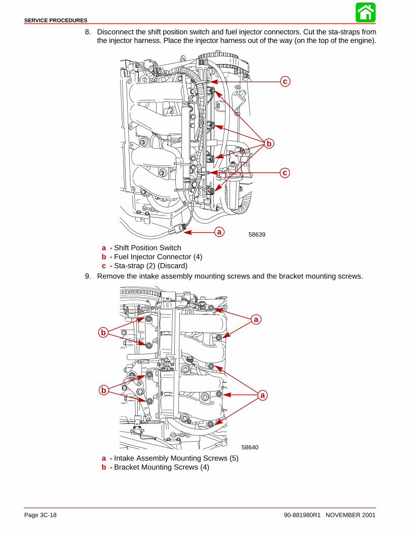
8. Disconnect the shift position switch and fuel injector connectors. Cut the sta-straps fromthe injector harness. Place the injector harness out of the way (on the top of the engine).
58639a
b
c
c
a - Shift Position Switchb - Fuel Injector Connector (4)c - Sta-strap (2) (Discard)
9. Remove the intake assembly mounting screws and the bracket mounting screws.
58640
ab
a
b
a - Intake Assembly Mounting Screws (5)b - Bracket Mounting Screws (4)

SERVICE PROCEDURES
90-881980R1 NOVEMBER 2001 Page 3C-19
Installation1. Install the intake assembly and tighten mounting screws to specified torque.
2. Install the bracket mounting screws and tighten to specified torque.
58640
ab
a
b
a - Intake Assembly Mounting Screws (5) M8 x 40b - Bracket Mounting Screws (4) M6 x 20
Intake Assembly Mounting Screw Torque
13 lb-ft. (18 Nm)
Bracket Mounting Screw Torque
70 lb-in (8 Nm)
3. Install vapor separator vent hose onto adaptor plate fitting.
58565
58632
a
a - Vapor Separator Vent Hose
SERVICE PROCEDURES
Page 3C-20 90-881980R1 NOVEMBER 2001
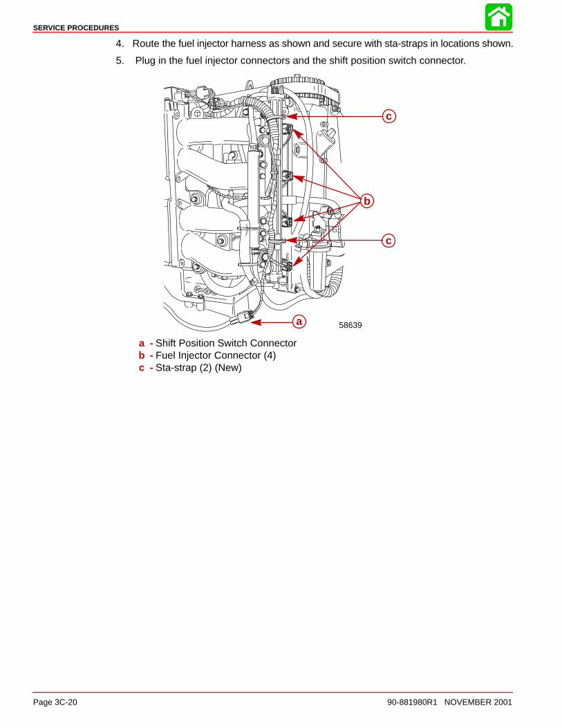
4. Route the fuel injector harness as shown and secure with sta-straps in locations shown.
5. Plug in the fuel injector connectors and the shift position switch connector.
58639a
b
c
c
a - Shift Position Switch Connectorb - Fuel Injector Connector (4)c - Sta-strap (2) (New)

SERVICE PROCEDURES
90-881980R1 NOVEMBER 2001 Page 3C-21
6. Plug in the following connectors: idle air control, throttle position sensor, MAP sensor,high pressure fuel pump.
7. Connect the fuel cooler water hoses (upper and lower) and secure with metal hoseclamp (retained from disassembly).
8. Connect the fuel pump hose and secure with sta-strap.
9. Install throttle and shift cables. Refer to Attachments/Control Linkage section of thismanual.
10. Install lower cowl. Refer to Mid - Section segment of this manual.
11. Install intake silencer assembly. Refer to Intake Silencer Assembly Installation .
ab
c
d
e
f
h
i
g
g
a - Throttle Position Sensor Connectorb - Idle Air Control Connectorc - MAP Sensor Connectord - High Pressure Fuel Pump Connectore - Fuel Cooler Upper Water Hosef - Fuel Cooler Lower Water Hoseg - Metal Hose Clamp (2) (Retained)h - Sta-strap (New)i - Fuel Pump Hose (fuel pump to vapor separator)

SERVICE PROCEDURES
Page 3C-22 90-881980R1 NOVEMBER 2001
Throttle Body
Removal1. Remove the intake silencer assembly. Refer to Intake Silencer Assembly Removal.
2. Disconnect the throttle link rod from the throttle control lever by carefully prying the plasticend off of the ball joint.
3. Remove bracket mounting screws.
58640
a
a
c
b
a - Bracket Mounting Screws (4) M6 x 25b - Throttle Link Rodc - Throttle Control Lever

SERVICE PROCEDURES
90-881980R1 NOVEMBER 2001 Page 3C-23
4. Remove throttle body mounting screws.
5. Disconnect air lines (throttle body to idle air control). Retain metal hose clamps forreassembly.
6. Remove the bracket mounting screws and remove the brackets from each throttle body(if required).
NOTE: When removing the throttle body assemblies be careful not to lose the dowel pinsand o-rings.
NOTE: When separating the upper and lower throttle body assemblies be careful not to losethe spring.
a
b c
d
c
f
e g
a - Bracket Mounting Screw (4) M6 x 25b - Air Lines (2) (throttle body to idle air control)c - Throttle Body Mounting Screw (6) M8 x 70d - Springe - Locating Pin (4)f - O-ring (4)g - Metal Hose Clamp (2) (Retain)

SERVICE PROCEDURES
Page 3C-24 90-881980R1 NOVEMBER 2001
Installation1. Assemble throttle body to intake manifold. Tighten screws to specified torque.
2. Assemble mounting brackets to throttle body. Tighten screws to specified torque.
3. Install spring between upper and lower throttle body as shown.
4. Connect air lines and secure with metal hose clamps.
5. Install intake silencer assembly. Refer to Intake Silencer Assembly Installation .
a
b c
c
f
e
g
d
a - Bracket Mounting Screw (4) M6 x 25b - Air Lines (2) (throttle body to idle air control)c - Throttle Body Mounting Screw (6) M8 x 70d - Springe - Locating Pin (4)f - O-ring (4)g - Metal Hose Clamp (2) (Retain)
Throttle Body Mounting Screw Torque
13 lb-ft.. (18 Nm)
Bracket Screw Torque
70 lb-in (8 Nm)

SERVICE PROCEDURES
90-881980R1 NOVEMBER 2001 Page 3C-25
Throttle Control Lever and Linkage
Removal1. Remove intake silencer assembly. Refer to Intake Silencer Assembly Removal .
2. Remove throttle control lever mounting screw.
3. Remove remaining components as shown.
4. Remove accelerator cam nut.
5. Remove remaining components as shown.
LTLT
4020
ab
cd
e
f
g
h
i
cd
95
95 2-4-C with Teflon
95
a - Mounting Screw (1) M6 x 30b - Collar(2)c - Wave Washer(2)d - Washer(3)e - Throttle Control Leverf - Springg - Accelerator Cam Nuth - Accelerator Cami - Stud Bolt

SERVICE PROCEDURES
Page 3C-26 90-881980R1 NOVEMBER 2001
Installation1. Install spring so tab locks into notch as shown.
LTLT
4020
ab
cd
e
f
g
h
i
cd
95
95 2-4-C with Teflon
95
58564j
a - Mounting Screw (1) M6 x 30b - Collar(2)c - Wave Washer(2)d - Washer(3)e - Throttle Control Leverf - Springg - Nuth - Accelerator Cami - Stud Boltj - Spring Tab
2. Reassemble components as shown above. Tighten accelerator cam nut and mountingscrew to specified torque.
Accelerator Cam Nut Torque
70 lb-in (8 Nm)
Throttle Control Lever Mounting Screw Torque
70 lb-in (8 Nm)

SERVICE PROCEDURES
90-881980R1 NOVEMBER 2001 Page 3C-27
High Pressure Fuel Line
WARNINGAlways release the fuel pressure in the high-pressure fuel line before servicing theline or the vapor sep arator. If the fuel pressure is not released, pressurized fuel mayspray out.
Releasing Fuel Pressure in the High-Pressure Fuel Line1. Install the fuel pressure gauge onto the pressure check valve.
2. Place the drain hose into a container.
3. Open the valve and release the pressure.
a b
c
91-16850A7
a
a - Fuel Pressure Gaugeb - Valvec - Drain Hose
SERVICE PROCEDURES
Page 3C-28 90-881980R1 NOVEMBER 2001
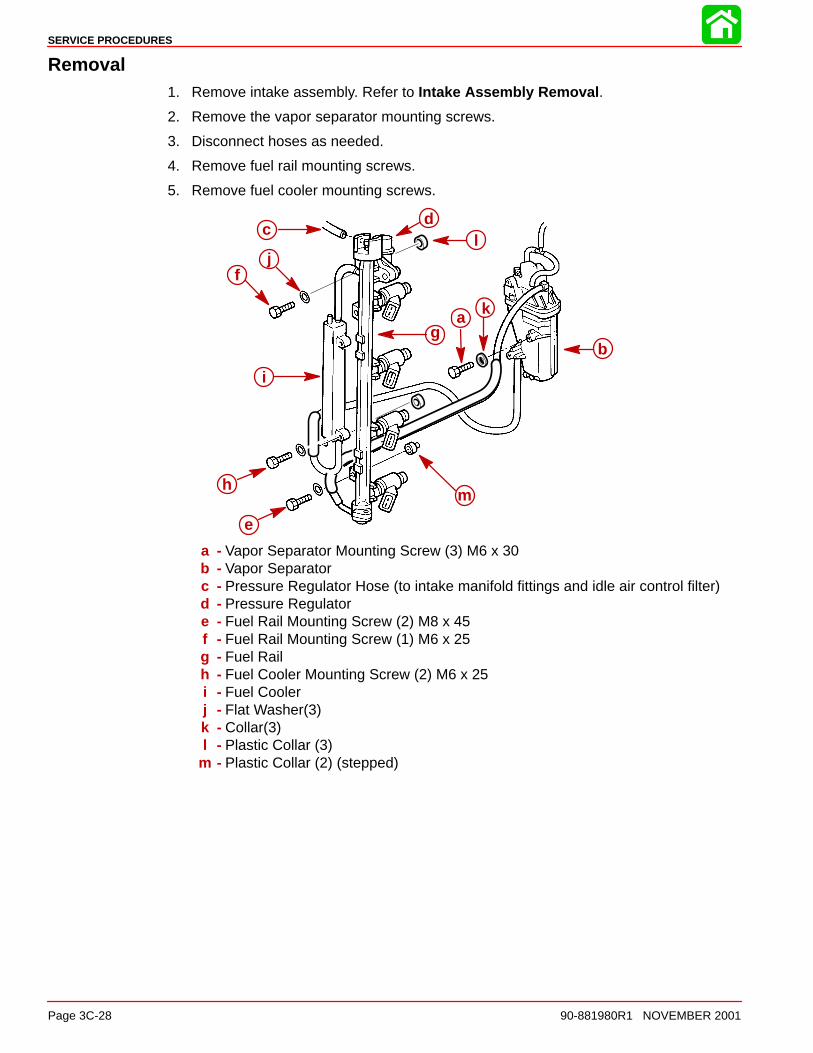
Removal1. Remove intake assembly. Refer to Intake Assembly Removal .
2. Remove the vapor separator mounting screws.
3. Disconnect hoses as needed.
4. Remove fuel rail mounting screws.
5. Remove fuel cooler mounting screws.
a
b
cd
f
g
h
i
e
k
jl
m
a - Vapor Separator Mounting Screw (3) M6 x 30b - Vapor Separatorc - Pressure Regulator Hose (to intake manifold fittings and idle air control filter)d - Pressure Regulatore - Fuel Rail Mounting Screw (2) M8 x 45f - Fuel Rail Mounting Screw (1) M6 x 25g - Fuel Railh - Fuel Cooler Mounting Screw (2) M6 x 25i - Fuel Coolerj - Flat Washer(3)k - Collar(3)l - Plastic Collar (3)
m - Plastic Collar (2) (stepped)

SERVICE PROCEDURES
90-881980R1 NOVEMBER 2001 Page 3C-29
Installation1. Assemble vapor separator to intake manifold. Tighten screws to specified torque.
2. Assemble fuel cooler and fuel rail to intake manifold. Tighten screws to specified torque.
3. Attach hoses as shown.
4. Assemble intake manifold assembly to engine. Refer to Intake Assembly Installation.
a
b
cd
f
g
h
i
e
k
jl
m
a - Vapor Separator Mounting Screw (3) M6 x 30b - Vapor Separatorc - Pressure Regulator Hose (to intake manifold fittings and idle air control filter)d - Pressure Regulatore - Fuel Rail Mounting Screw (2) M8 x 45f - Fuel Rail Mounting Screw (1) M6 x 25g - Fuel Railh - Fuel Cooler Mounting Screw (2) M6 x 25i - Fuel Coolerj - Flat Washer(3)k - Collar(3)l - Plastic Collar (3)
m - Plastic Collar (2) (stepped)
Vapor Separator Mounting Screw Torque
70 lb-in (8 Nm)
Fuel Rail Mounting Screw Torque (M8 x 45)
13 lb-ft. (18 Nm)
Fuel Rail/Fuel Cooler Mounting Screw Torque (M6 x 25)
70 lb-in (8 Nm)

SERVICE PROCEDURES
Page 3C-30 90-881980R1 NOVEMBER 2001
Fuel Cooler
Removal/InstallationREMOVAL
1. Cut sta-straps and remove fuel cooler mounting screws.
NOTE: When removing the mounting screws, be careful not to lose the spacers betweenfuel cooler base and intake manifold.
2. Disconnect the fuel cooler water and fuel hoses. Retain metal hose clamps.
INSTALLATION
1. Connect fuel cooler water and fuel hoses and secure with metal hose clamps (retainedfrom disassembly).
2. Install fuel cooler mounting screws and spacers. Tighten screws to specified torque.
3. Attach sta-straps as shown.
58639
c
ef
a
b
g
g
g
g
e
cd
f
a - Fuel Coolerb - Sta-Strap (2)c - Mounting Screw (2)(M6 x 30)d - Spacer (2)
e - Water Hosef - Fuel Hoseg - Metal Hose Clamp (4) (Retain)
Fuel Cooler Mounting Screw Torque
70 lb-in (8 Nm)

SERVICE PROCEDURES
90-881980R1 NOVEMBER 2001 Page 3C-31
Fuel Hoses
Removal/InstallationREMOVAL
1. Remove intake assembly. Refer to Intake Assembly Removal.
2. Remove hoses as shown below. Retain metal hose clamps.
INSTALLATION
1. Reconnect hoses as shown below.
2. Secure fuel hoses with metal hose clamps (retained from disassembly).
3. Install intake assembly. Refer to Intake Assembly Installation.
a
b
c
da
a
a
a
a - Metal Hose Clamp (6) (Retain)b - Fuel Hose (Vapor Separator to Fuel Rail)c - Fuel Hose (Pressure Regulator to Fuel Cooler)d - Fuel Hose (Fuel Cooler to Vapor Separator)

SERVICE PROCEDURES
Page 3C-32 90-881980R1 NOVEMBER 2001
Fuel Injectors
Removal/InstallationREMOVAL
1. Remove fuel rail from intake manifold. Refer to High Pressure Fuel Line Removal.
2. Remove the fuel injectors from the fuel rail (twist while pulling out).
INSTALLATION
1. Lubricate the o-ring.
2. Install the fuel injector into the fuel rail.
3. Install the fuel rail assembly to the intake manifold. Refer to High Pressure Fuel LineInstallation.
b
c
ad
e
f
a - Fuel Injectorb - Fuel Railc - Intake Manifoldd - O-ringe - Rubber Damperf - Rubber Seal

SERVICE PROCEDURES
90-881980R1 NOVEMBER 2001 Page 3C-33
Fuel Rail
Disassembly/AssemblyDISASSEMBLY
1. Remove fuel rail from intake manifold. Refer to High Pressure Fuel Line Remova l.
2. Remove fuel injectors from fuel rail. Refer to Fuel Injector Removal.
3. Remove fuel hoses. Refer to Fuel Hose Removal.
4. Remove pressure regulator. Refer to Pressure Regulator Removal.
5. Remove fuel rail joint screws. Remove fuel rail joint.
ASSEMBLY
1. Lubricate o-ring and install onto fuel rail joint.
2. Install fuel rail joint onto fuel rail and tighten screws to specified torque.
3. Install pressure regulator. Refer to Pressure Regulator Installation .
4. Install fuel hoses. Refer to Fuel Hose Installation.
5. Install fuel injectors onto fuel rail. Refer to Fuel Injector Installation.
6. Install fuel rail onto intake manifold. Refer to High Pressure Fuel Line Installation .
a
b
c
de
a - Capb - Fuel Railc - O-ringd - Fuel Rail Jointe - Fuel Rail Joint Screw (2) M5 x 10
Fuel Rail Joint Screw Torque
43 lb-in (5 Nm)

SERVICE PROCEDURES
Page 3C-34 90-881980R1 NOVEMBER 2001
Vapor Separator
Removal1. Remove the intake manifold assembly. Refer to Intake Assembly Removal.
2. Remove the following fuel lines: vapor separator to fuel cooler (reuse metal hoseclamps), vapor separator to fuel rail (discard the metal hose clamps from this hose).
58639a b
a - Fuel Hose (vapor separator to fuel cooler)b - Fuel Hose (vapor separator to fuel rail)
3. Remove the vapor separator mounting screws. Remove the vapor separator.
a
b
a - Vapor Separator Mounting Screw (3) M6 x 30b - Vapor Separator
Installation1. Assemble the vapor separator to the intake manifold as shown in the illustration above.
Tighten mounting screws to specified torque.
2. Connect the following fuel lines: vapor separator to fuel cooler (secure with metal hoseclamps retained from disassembly), vapor separator to fuel rail (install new metal hoseclamps on this hose).
3. Install the intake manifold assembly. Refer to Intake Assembly Installation.
Vapor Separator Mounting Screw Torque
70 lb-in (8 Nm)

SERVICE PROCEDURES
90-881980R1 NOVEMBER 2001 Page 3C-35
Disassembly1. Remove top cover screws. Remove top cover assembly.
2. Remove high pressure fuel pump filter and holder. Inspect filter for debris and clean ifnecessary.
a b
c
d
e
f
a - Top Cover Screw (7) M4 x 16b - Top Cover Assemblyc - High Pressure Fuel Pump Filterd - Holdere - O-ringf - Float Chamber
3. Remove float pin by pressing on the round end, NOT THE SQUARE END. Drive the pinout in the direction shown.
a
b
c
a - Float Pinb - Square Endc - Round End
SERVICE PROCEDURES
Page 3C-36 90-881980R1 NOVEMBER 2001
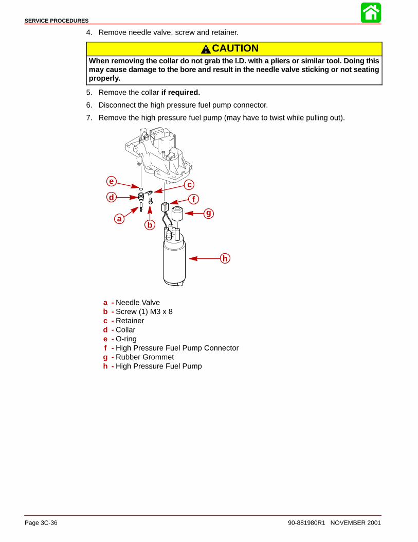
4. Remove needle valve, screw and retainer.
CAUTIONWhen removing the collar do not grab the I.D. with a pliers or similar tool. Doing thismay cause damage to the bore and result in the needle valve sticking or not seatingproperly.
5. Remove the collar if required.
6. Disconnect the high pressure fuel pump connector.
7. Remove the high pressure fuel pump (may have to twist while pulling out).
ab
c
d
e
f
g
h
a - Needle Valveb - Screw (1) M3 x 8c - Retainerd - Collare - O-ringf - High Pressure Fuel Pump Connectorg - Rubber Grommeth - High Pressure Fuel Pump

SERVICE PROCEDURES
90-881980R1 NOVEMBER 2001 Page 3C-37
Assembly1. Lubricate o-ring on collar and install collar (if removed). Twist collar while pushing in.
2. Install retainer and tighten screw.
3. Install needle valve in collar.
4. Install float and float pin (round end of pin should be installed first) . Float pin endshould be flush with surface.
5. Plug in high pressure fuel pump connector.
6. Install the rubber grommet into the top cover assembly. Install the high pressure fuelpump barb end into the rubber grommet (apply lubricant if necessary).
ab
c
d
e
f
g
i
j
h
k
a - Needle Valveb - Screw (1) M3 x 8c - Retainerd - Collare - O-ringf - High Pressure Fuel Pump Connectorg - Rubber Grommeth - High Pressure Fuel Pumpi - Float Pinj - Square Endk - Round End
SERVICE PROCEDURES
Page 3C-38 90-881980R1 NOVEMBER 2001
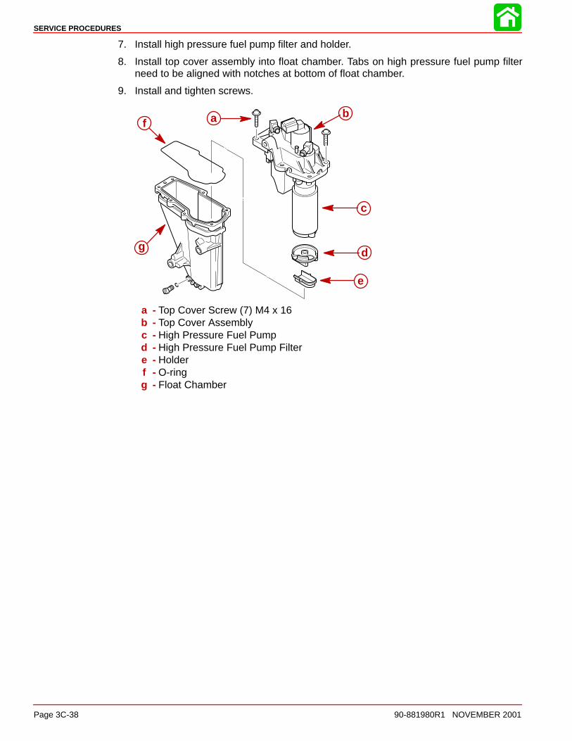
7. Install high pressure fuel pump filter and holder.
8. Install top cover assembly into float chamber. Tabs on high pressure fuel pump filterneed to be aligned with notches at bottom of float chamber.
9. Install and tighten screws.
a b
d
e
f
g
c
a - Top Cover Screw (7) M4 x 16b - Top Cover Assemblyc - High Pressure Fuel Pumpd - High Pressure Fuel Pump Filtere - Holderf - O-ringg - Float Chamber
SERVICE PROCEDURES
90-881980R1 NOVEMBER 2001 Page 3C-39
Pressure Regulator
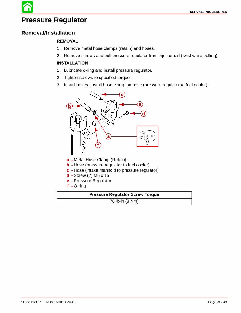
Removal/InstallationREMOVAL
1. Remove metal hose clamps (retain) and hoses.
2. Remove screws and pull pressure regulator from injector rail (twist while pulling).
INSTALLATION
1. Lubricate o-ring and install pressure regulator.
2. Tighten screws to specified torque.
3. Install hoses. Install hose clamp on hose (pressure regulator to fuel cooler).
a
b
c
d
e
f
a - Metal Hose Clamp (Retain)b - Hose (pressure regulator to fuel cooler)c - Hose (intake manifold to pressure regulator)d - Screw (2) M6 x 15e - Pressure Regulatorf - O-ring
Pressure Regulator Screw Torque
70 lb-in (8 Nm)

SERVICE PROCEDURES
Page 3C-40 90-881980R1 NOVEMBER 2001
Idle Speed Control AssemblyRemoval/Installation
REMOVAL
1. Remove intake assembly. Refer to Intake Assembly Removal.
2. Disconnect vacuum hose from filter.
3. Remove idle air control mounting screws.
4. Remove idle air control assembly.
5. Remove metal hose clamps (retain) and hoses as needed.
INSTALLATION
1. Install idle air control assembly. Tighten screws to specified torque.
2. Connect vacuum hose to filter.
3. Connect air hoses and secure with metal hose clamps (retained from disassembly).
4150
a
b
c
d
e
f h
g
i
j
a - Filterb - Vacuum Hose (idle air control to intake manifold)c - Idle Air Control Mounting Screw (2) M8 x 60d - Idle Air Control Mounting Screw (1) M8 x 24e - Idle Air Control Assemblyf - Hose (idle air control assembly to throttle body #2)g - Hose (idle air control assembly to throttle body #1)h - Metal Hose Clamp (4) (Retain)i - Throttle Body #1j - Throttle Body #2
Idle Air Control Assembly Mounting Screw Torque
156 lb-in (18 Nm)

SERVICE PROCEDURES
90-881980R1 NOVEMBER 2001 Page 3C-41
Disassembly/AssemblyDISASSEMBLY
1. Remove pressure sensor screws and pressure sensor (twist while pulling).
2. Remove idle air control screws. Remove air speed control from idle air control body.
3. Remove filter.
ASSEMBLY
1. Install filter.
2. Install idle air control to idle air control body.
3. Install the manifold absolute pressure (MAP) sensor and tighten screws to specifiedtorque.
a
b
c
d
e
f
g
h
a - MAP Sensor Screws (2) M5 x 15b - MAP Sensorc - O-ringd - Screw (3) M4 x 15e - Idle Air Controlf - O-ringg - Idle Air Control Bodyh - Filter (24mm Hex)
Manifold Absolute Pressure Sensor Mounting Screw Torque
43 lb-in (5 Nm)
Idle Air Control Mounting Screw Torque
18 lb-in (2 Nm)

SERVICE PROCEDURES
Page 3C-42 90-881980R1 NOVEMBER 2001
Intake Manifold
Disassembly/AssemblyDISASSEMBLY
1. Remove intake assembly. Refer to Intake Assembly Removal.
2. Remove throttle body, high pressure fuel line, vapor separator, fuel rail and idle air con-trol assembly. Refer to appropriate segment in this section for removal instructions.
3. Remove components as as shown in illustration.
ASSEMBLY
1. Install components as shown in illustration.
2. Install throttle body, high pressure fuel line, vapor separator, fuel rail and idle speed con-trol assembly. Refer to appropriate segment in this section for installation instructions.
a
b
c
dd
e
a - Hose (pressure regulator to intake manifold to idle speed control assembly)b - Rubber Seal (4) (Fuel Injector)c - Intake Manifoldd - Collar (6) (Vapor Separator Mount)e - Grommet (3) (Vapor Separator Mount)

SERVICE PROCEDURES
90-881980R1 NOVEMBER 2001 Page 3C-43
Throttle Position Sensor
Removal/InstallationREMOVAL
1. Disconnect throttle position sensor connector.
2. Remove the tamper proof screws for the bracket (covering the throttle position sensor)and throttle position sensor using special tool p/n 91-881828.
INSTALLATION
1. Install throttle position sensor and torque tamper proof screws using special tool91-882828.
2. Install the bracket and torque tamper proof screws using special tool 91-881828.
3. Connect throttle position sensor connector. Refer to section 2C Timing, Synchroniz-ing and Adjusting for adjustment of the throttle position sensor.
58634
fg
h
i
5868591-881828 e
b
dc
a
a - Throttle Position Sensorb - Washer (2)c - Washer (2)d - Tamper Proof Screw (2) M4 x 12
(T20)
e - Bracketf - Lock Washer (3)g - Spool (3)h - Washer (3) (Cupped)i - Tamper Proof Screw (3) M5 x 12
(T25)
Throttle Position Sensor Tamper Proof Screw Torque
18 lb-in (2 Nm)
Bracket Tamper Proof Screw Torque
40 lb-in (5 Nm)

SERVICE PROCEDURES
Page 3C-44 90-881980R1 NOVEMBER 2001
Low Pressure Fuel Line/Fuel PumpRemoval
1. Remove grommet retaining plate.
2. Cut sta-strap and remove fuel hose from grommet.
a
c
d
e
b
a - Grommet Retaining Plateb - Screw (2) M6 x 28c - Fuel Hose Openingd - Rubber Grommete - Sta-Strap (Discard)
3. Remove spark plug cover.
4. Disconnect fuel hose from fuel pump and fuel filter.
5. Remove fuel pump. Remove fuel filter mounting bracket assembly.
a
bcd
f
g h
i
e
j
k
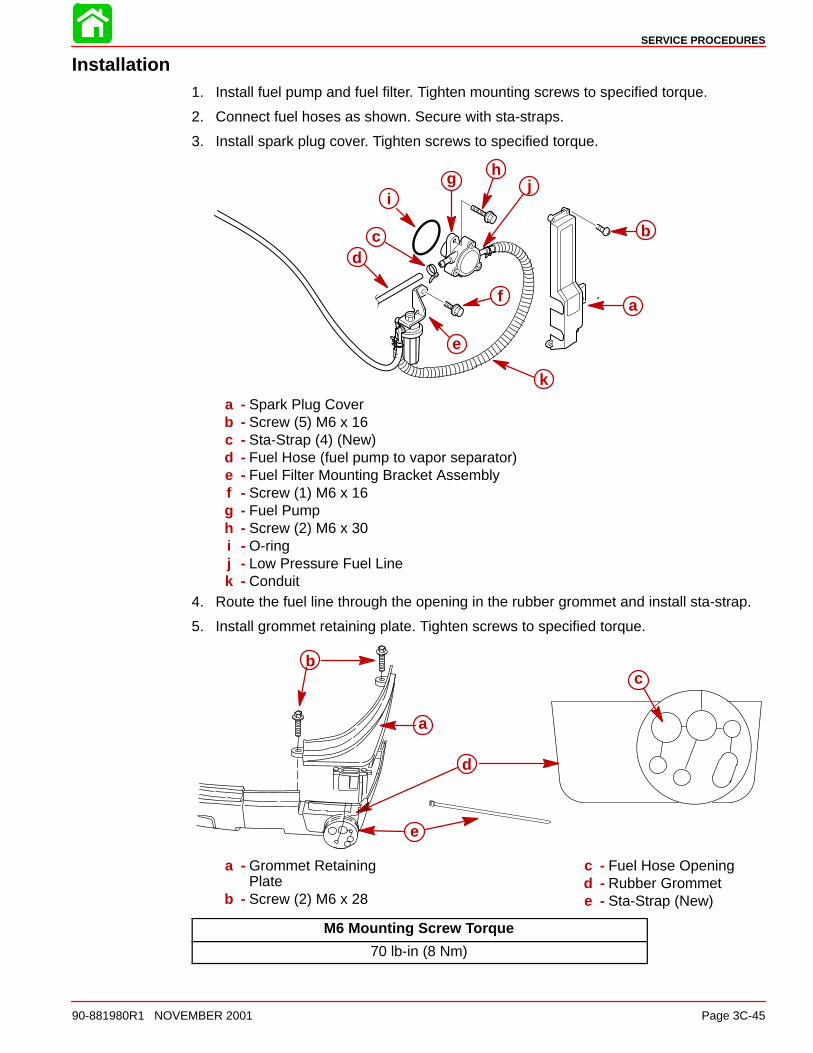
a - Spark Plug Coverb - Screw (5) M6 x 16c - Sta-Strap (4) (Discard)d - Fuel Hose (fuel pump to vapor separator)e - Fuel Filter Mounting Bracket Assemblyf - Screw (1) M6 x 16g - Fuel Pumph - Screw (2) M6 x 30i - O-ringj - Low Pressure Fuel Linek - Conduit
SERVICE PROCEDURES
90-881980R1 NOVEMBER 2001 Page 3C-45
Installation1. Install fuel pump and fuel filter. Tighten mounting screws to specified torque.
2. Connect fuel hoses as shown. Secure with sta-straps.
3. Install spark plug cover. Tighten screws to specified torque.
a
bcd
f
g h
i
e
j
k
a - Spark Plug Coverb - Screw (5) M6 x 16c - Sta-Strap (4) (New)d - Fuel Hose (fuel pump to vapor separator)e - Fuel Filter Mounting Bracket Assemblyf - Screw (1) M6 x 16g - Fuel Pumph - Screw (2) M6 x 30i - O-ringj - Low Pressure Fuel Linek - Conduit
4. Route the fuel line through the opening in the rubber grommet and install sta-strap.
5. Install grommet retaining plate. Tighten screws to specified torque.
a
bc
d
e
a - Grommet RetainingPlate
b - Screw (2) M6 x 28
c - Fuel Hose Openingd - Rubber Grommete - Sta-Strap (New)
M6 Mounting Screw Torque
70 lb-in (8 Nm)
SERVICE PROCEDURES
Page 3C-46 90-881980R1 NOVEMBER 2001
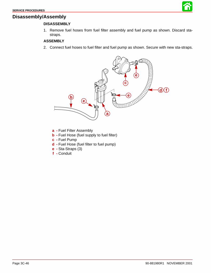
Disassembly/AssemblyDISASSEMBLY
1. Remove fuel hoses from fuel filter assembly and fuel pump as shown. Discard sta-straps.
ASSEMBLY
2. Connect fuel hoses to fuel filter and fuel pump as shown. Secure with new sta-straps.
a
b
d
ee
f
c
e
a - Fuel Filter Assemblyb - Fuel Hose (fuel supply to fuel filter)c - Fuel Pumpd - Fuel Hose (fuel filter to fuel pump)e - Sta-Straps (3)f - Conduit
SERVICE PROCEDURES
90-881980R1 NOVEMBER 2001 Page 3C-47
Fuel Filter
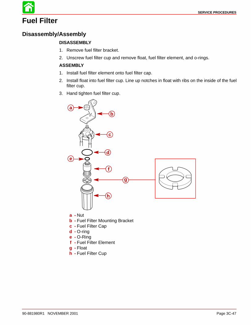
Disassembly/AssemblyDISASSEMBLY
1. Remove fuel filter bracket.
2. Unscrew fuel filter cup and remove float, fuel filter element, and o-rings.
ASSEMBLY
1. Install fuel filter element onto fuel filter cap.
2. Install float into fuel filter cup. Line up notches in float with ribs on the inside of the fuelfilter cup.
3. Hand tighten fuel filter cup.
ab
c
de
f
g
h
a - Nutb - Fuel Filter Mounting Bracketc - Fuel Filter Capd - O-ringe - O-Ringf - Fuel Filter Elementg - Floath - Fuel Filter Cup

SERVICE PROCEDURES
Page 3C-48 90-881980R1 NOVEMBER 2001
Fuel Pump
Disassembly1. Remove fuel pump assembly from engine.
2. Remove fuel pump cover.
3. Remove fuel pump body from fuel pump base assembly.
4. Disassemble as shown.
58637
LTLTa
b
c
de
a - Fuel Pump Bodyb - Fuel Pump Base Assemblyc - Fuel Pump Coverd - Gaskete - Screw (3) M6 x 35
5. Insert screwdriver in the plunger slot and rotate until the pin lines up with the groove.
58636
a
b c
a - Plungerb - Groovec - Fuel Pump Base Assembly

SERVICE PROCEDURES
90-881980R1 NOVEMBER 2001 Page 3C-49
CAUTIONPlunger is spring loaded. Place the fuel pump assembly on a bench top (so plungeris facing down) before pulling the pin completely out. Failure to do this could resultin injury due to objects flying through the air.
6. Insert screwdriver in back side of slot and push pin out. Grab pin with a needle nose andpull completely out.
58635
ba
a - Pinb - Plunger
7. Disassemble components as shown.
a
b
c
d
e
f
g
a - Diaphragmb - Springc - Fuel Pump Based - Springe - Plungerf - Ping - Nut

SERVICE PROCEDURES
Page 3C-50 90-881980R1 NOVEMBER 2001
Assembly1. Install components as shown.
a
b
c
d
e
f
a - Diaphragmb - Springc - Fuel Pump Based - Springe - Plungerf - Pin
2. Push down on the plunger until the groove lines up with the hole in the end of the dia-phragm shaft. Insert pin.
58635
ab
c
a - Pinb - Plungerc - Hole in Diaphragm Shaft
3. Rotate plunger back to original position (pin should be 90° from groove).
58636
b
a
c
a - Plungerb - Groovec - Fuel Pump Base Assembly

SERVICE PROCEDURES
90-881980R1 NOVEMBER 2001 Page 3C-51
4. Alignment marks on fuel pump body, base assembly and cover should be as shown be-low. Assemble fuel pump body, cover, and new gasket to fuel pump base. Apply Loctite242 (obtain locally) and tighten screws to specified torque.
58637Loctite 242 Thread Locker
b
ead
c
f
66
66
a - Fuel Pump Bodyb - Fuel Pump Base Assemblyc - Fuel Pump Coverd - Gasket (NEW)e - Screw (3) M6 x 35f - Nut (3)
M6 Mounting Screw Torque
70 lb-in (8 Nm)