Electronic Devices for the Mechanical Experimenter*
15
Electronic Devices for the Mechanical Experimenter* Nathan Delson le inspired by book, Mechanical Devices for the Electronics Experime
-
Upload
buthainah-feroze -
Category
Documents
-
view
47 -
download
0
description
Electronic Devices for the Mechanical Experimenter*. Nathan Delson. *Title inspired by book, Mechanical Devices for the Electronics Experimenter. MEs are Responsible for More and More EE Design. Electronics and Microprocessors are pervasive in mechanical devices - PowerPoint PPT Presentation
Transcript of Electronic Devices for the Mechanical Experimenter*
Electronic Devices for the Mechanical Experimenter*Electronic Devices for the Mechanical Experimenter*
Nathan DelsonNathan Delson
*Title inspired by book, Mechanical Devices for the Electronics Experimenter
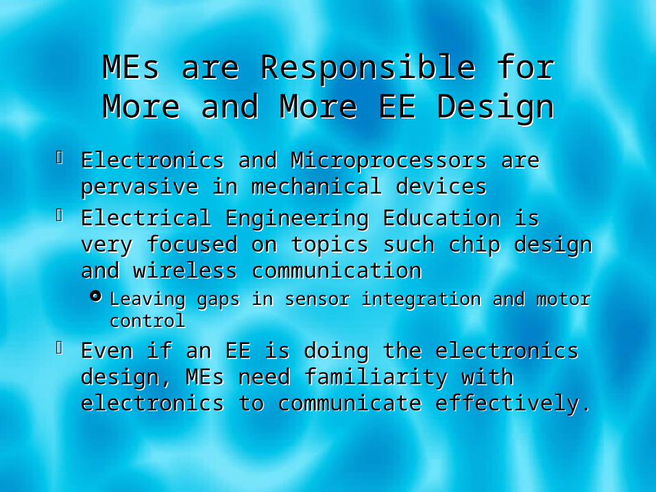
MEs are Responsible for More and More EE Design
MEs are Responsible for More and More EE Design
Electronics and Microprocessors are pervasive in mechanical devices
Electrical Engineering Education is very focused on topics such chip design and wireless communication Leaving gaps in sensor integration and motor control
Even if an EE is doing the electronics design, MEs need familiarity with electronics to communicate effectively.
Good Electronic Design vs. Bad Electronic Design
Good Electronic Design vs. Bad Electronic Design
Bad EE Design Copy circuits without voltage or current calculations,
and no use of spec sheets Circuits seem to work or not by “magic”Good EE Design Use of specification (spec) sheets Clear circuit diagrams, with voltage AND current
calculations Step by step implementation, with verification of each
step with a voltmeter or oscilloscope Good wiring habits: consistent colors, strain relief, and
others described on the “Hands-on Guidelines for Good Circuit Implementation”
Like with ME Components, EE Components have input, output, and
power specs
Like with ME Components, EE Components have input, output, and
power specsExample of an ME Component Specs: Transmissions Input speed and torque Output speed and torque Power rating Other specs: Friction, backlash, size, weight, …
Specs for EE Components Include Input voltage and current Output voltage and current Overall power dissipation and power handling capabilities
Remember: P = VI
Example of an ME Component Specs: Transmissions Input speed and torque Output speed and torque Power rating Other specs: Friction, backlash, size, weight, …
Specs for EE Components Include Input voltage and current Output voltage and current Overall power dissipation and power handling capabilities
Remember: P = VI

Categories of EE ComponentsCategories of EE Components
High Power vs Low Power
Analog vs Digital
Microprocessor
On/Off switch
Potentiometer
Optical Sensor
LED
Motor

Categories of EE ComponentsCategories of EE Components
High Power vs Low Power
Analog vs Digital
Microprocessor low power digital
On/Off switch low power digital
Potentiometer low power analog
Optical Sensor low power either
LED low power either
Motor high power analog
Light Emitting Diode (LED)Light Emitting Diode (LED)
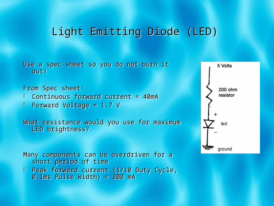
Use a spec sheet so you do not burn it out!
From Spec sheet: Continuous forward current = 40mA Forward Voltage = 1.7 V
What resistance would you use for maximum LED brightness?
Many components can be overdriven for a short period of time
Peak forward current (1/10 Duty Cycle, 0.1ms Pulse Width) = 200 mA

Microprocessor: The 16F877A PIC on the X2 Board
Microprocessor: The 16F877A PIC on the X2 Board
16F877A PIC is a digital microprocessor where 0V corresponds to low (logical 0), and 5V corresponds to high (logical 1)
Key Features 33 total I/O pins 8 analog inputs (10 bit) 2 hardware PWM output channels Total memory: 14336 bytes
Specs for digital input reads low for v<0.8 and high for V> 2
Specs for Digital Output with a 5V supply maintains low (V=0 to 0.6) by sinking up to 25 mA per pin maintains high (V=5 to 4.7) by sourcing up to 25 mA per pin Total of all pins cannot source or sink more than 200 mA.

Input Switch – INCORRECT MethodInput Switch – INCORRECT Method

Input Switch Correct Method: Avoids Floating Input
Input Switch Correct Method: Avoids Floating Input
Brain teaser: Can you connect switch so signal to PIC is low when switch is closed, and high when switch is open.
Brain teaser: Can you connect switch so signal to PIC is low when switch is closed, and high when switch is open.

PotentiometerPotentiometer
How would you hook up a potentiometer so it could generate available input voltage to be read by a PIC?
How would you hook up a potentiometer so it could generate available input voltage to be read by a PIC?
voltagemeasuringdevice
5VDC
R1
R2
I1
I3V2
V1
I2
poteniometer wiper
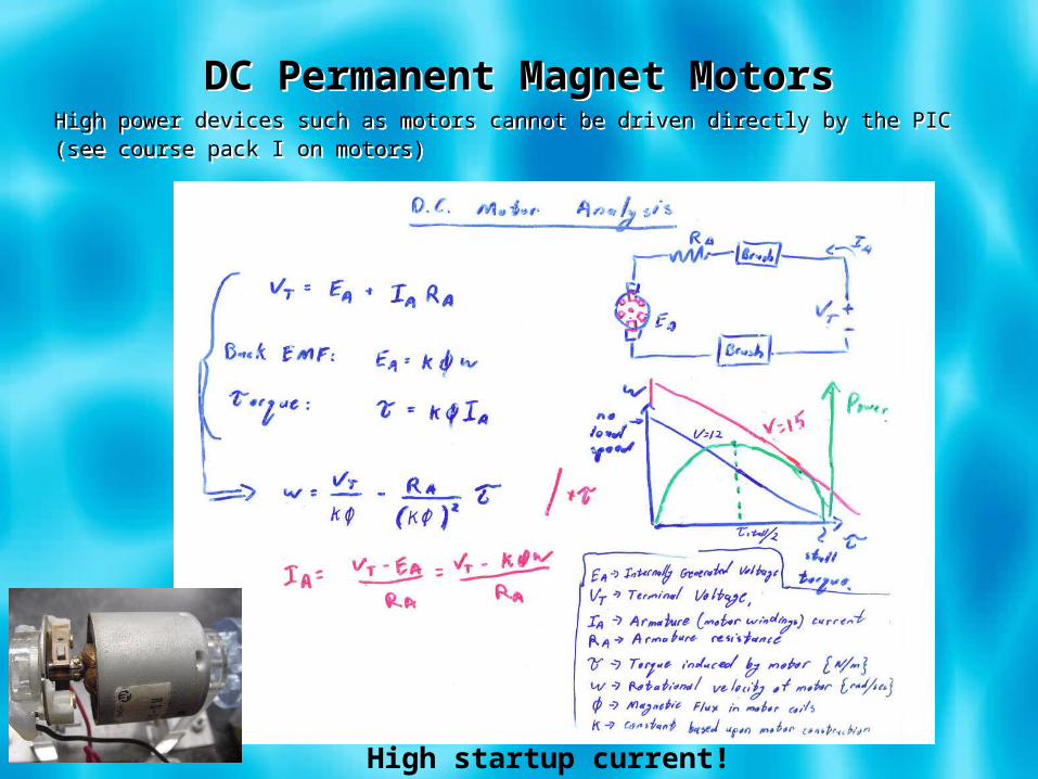
DC Permanent Magnet MotorsDC Permanent Magnet MotorsHigh power devices such as motors cannot be driven directly by the PIC(see course pack I on motors)High power devices such as motors cannot be driven directly by the PIC(see course pack I on motors)
High startup current!

MotoMaster Motor DriverDesigned by Alex Simpkins of UCSDMotoMaster Motor DriverDesigned by Alex Simpkins of UCSD
PWM Control for Speed Transistors are much more efficient in on or off state
than intermediate “op-amp” state Pulse Width Modulation pulses the voltage on and off
much more quickly than the motor can respond, resulting in an effective average voltage based upon duty cycle
PWM Control for Speed Transistors are much more efficient in on or off state
than intermediate “op-amp” state Pulse Width Modulation pulses the voltage on and off
much more quickly than the motor can respond, resulting in an effective average voltage based upon duty cycle
H-Bridge for Bi-directional Control

RelaysRelays
Mechanical switch activated by an electromagnet, thereby switching large current with only a small current input
Disadvantage: Much slower than transistors, so PWM control is not possible
Advantage: No voltage drop as with most H-bridges transistors
Hands-on Guidelines for Good Circuit Implementation
Hands-on Guidelines for Good Circuit Implementation