Electron beam machining (ebm)
23
Electron Beam Machining Er. Mohit Ostwal Assistant Professor Department of Mechanical Engineering Jodhpur Institute of Engineering and Technology, Jodhpur 03/12/2022 Er. Mohit Ostwal Asst. Prof. JIET- Jodhpur 1
-
Upload
mohit99033 -
Category
Engineering
-
view
2.483 -
download
11
Transcript of Electron beam machining (ebm)
05/0
2/20
23Er
. Moh
it O
stw
al
Asst
. Pro
f. JIE
T-Jo
dhpu
r
Electron Beam Machining
Er. Mohit OstwalAssistant ProfessorDepartment of Mechanical EngineeringJodhpur Institute of Engineering and Technology, Jodhpur
1
05/0
2/20
23Er
. Moh
it O
stw
al
Asst
. Pro
f. JIE
T-Jo
dhpu
r
Content• Introduction• Equipment/Setup• Process• Mechanism of material removal• How vacuum is created?• Process capabilities• Advantages• Disadvantages• Application
2
05/0
2/20
23Er
. Moh
it O
stw
al
Asst
. Pro
f. JIE
T-Jo
dhpu
r
Introduction - EBM• Electron beam machining (EBM) is a thermal material removal
process that utilizes a focused beam of high-velocity electrons to perform high-speed drilling and cutting.
• Used with high power density to machine materials.• The mechanism of material removal is primarily by melting
and rapid vaporization due to intense heating by the electrons • Also known as “Electro-optical-thermal process”.• Very high drilling rates are achievable.• Can machine almost any material.
3
05/0
2/20
23Er
. Moh
it O
stw
al
Asst
. Pro
f. JIE
T-Jo
dhpu
r
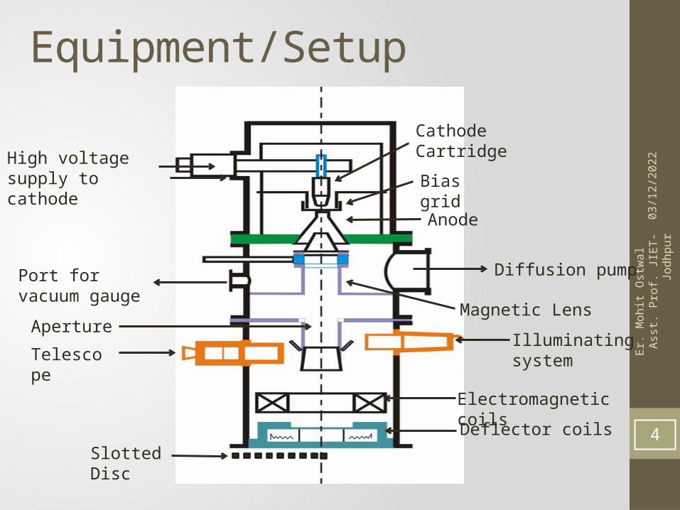
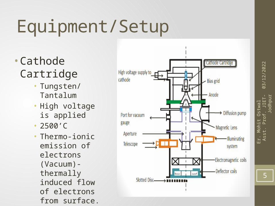
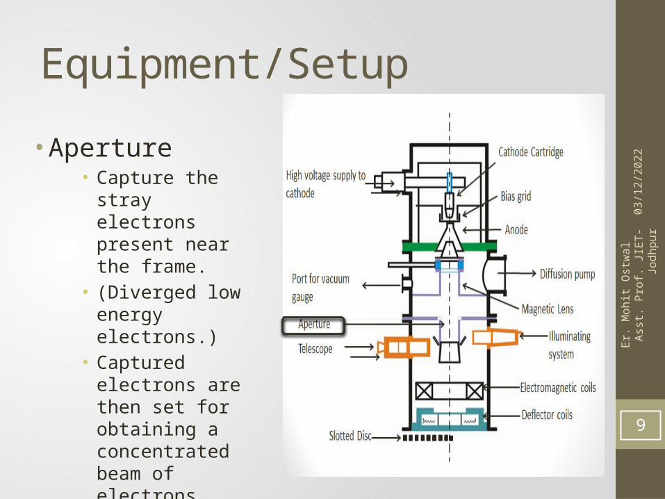
Equipment/Setup
High voltage supply to cathode
Cathode Cartridge
Bias grid
Anode
Port for vacuum gauge
Diffusion pump
Magnetic Lens
Illuminating system
Aperture
Telescope
Electromagnetic coils
Deflector coilsSlotted Disc
4
05/0
2/20
23Er
. Moh
it O
stw
al
Asst
. Pro
f. JIE
T-Jo
dhpu
r
Equipment/Setup
• Cathode Cartridge• Tungsten/Tantalum• High voltage is
applied• 2500’C• Thermo-ionic
emission of electrons (Vacuum)- thermally induced flow of electrons from surface.
• Negatively biased – repel the electrons 5
05/0
2/20
23Er
. Moh
it O
stw
al
Asst
. Pro
f. JIE
T-Jo
dhpu
r
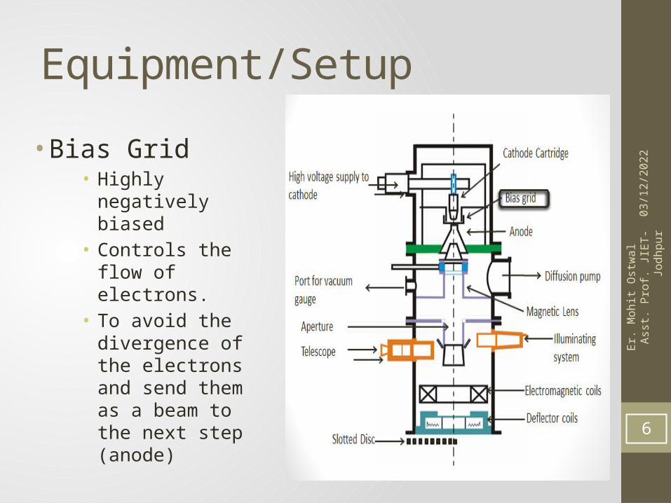
Equipment/Setup
• Bias Grid• Highly negatively
biased• Controls the flow of
electrons.• To avoid the
divergence of the electrons and send them as a beam to the next step (anode)
6
05/0
2/20
23Er
. Moh
it O
stw
al
Asst
. Pro
f. JIE
T-Jo
dhpu
r
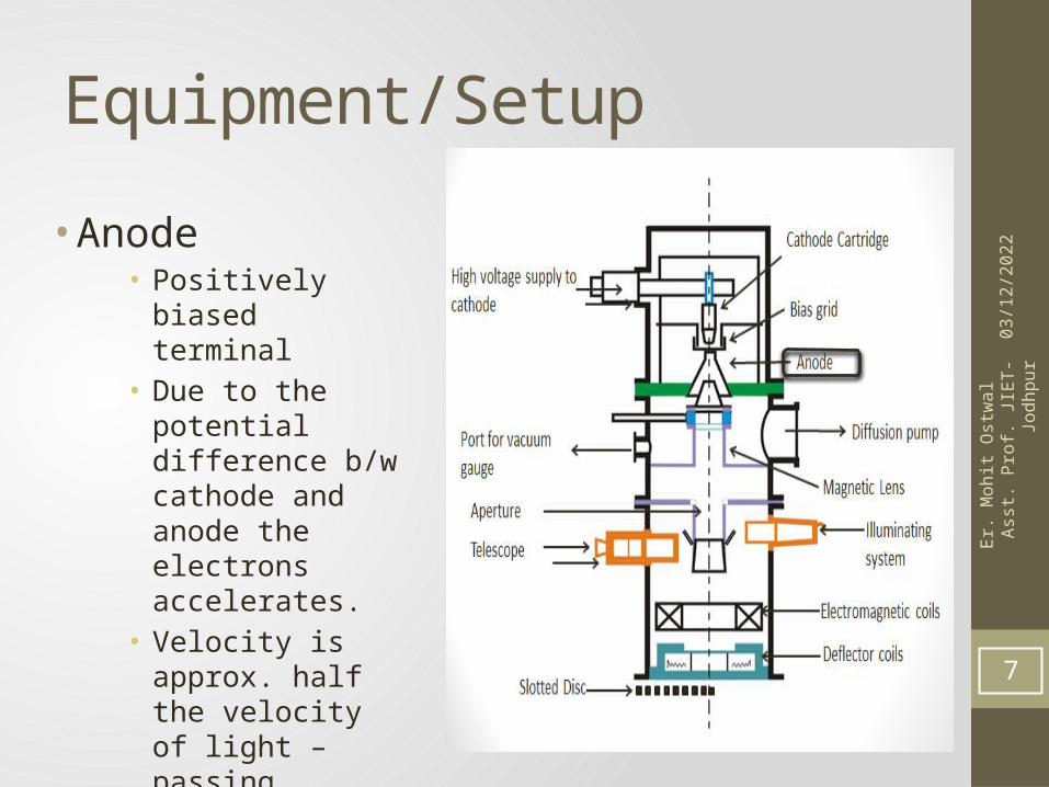
Equipment/Setup
• Anode• Positively biased
terminal• Due to the potential
difference b/w cathode and anode the electrons accelerates.
• Velocity is approx. half the velocity of light – passing through anode.
7
05/0
2/20
23Er
. Moh
it O
stw
al
Asst
. Pro
f. JIE
T-Jo
dhpu
r
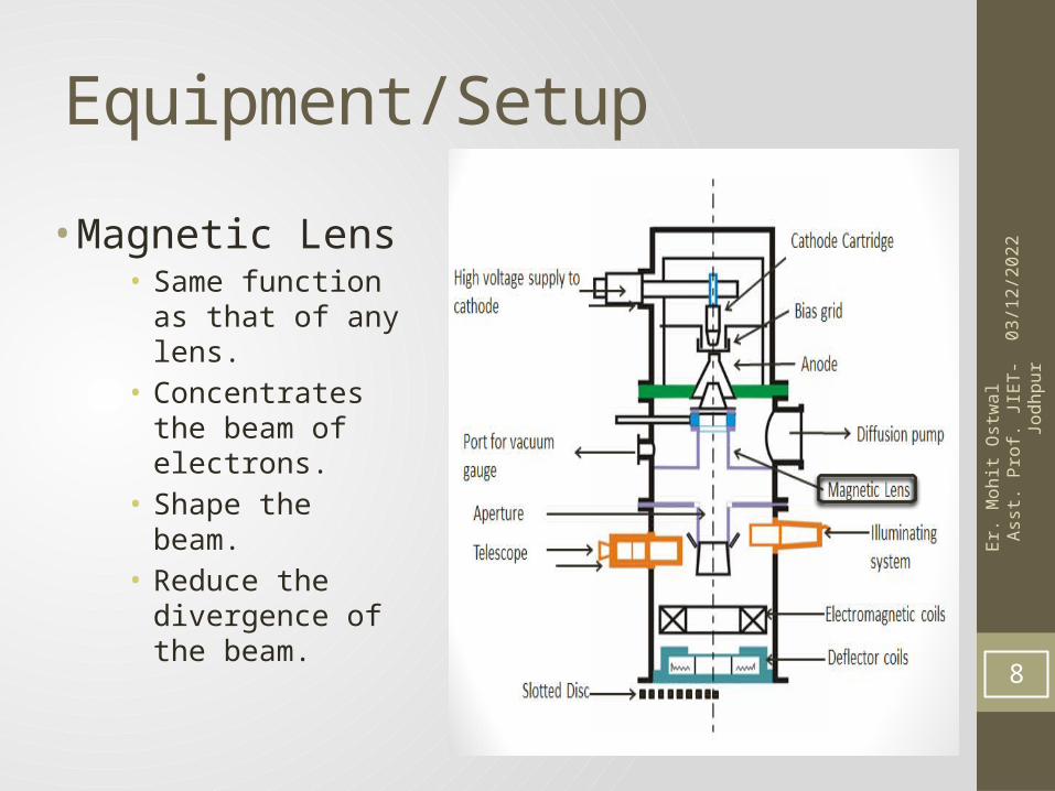
Equipment/Setup
• Magnetic Lens• Same function as
that of any lens.• Concentrates the
beam of electrons.• Shape the beam.• Reduce the
divergence of the beam.
8
05/0
2/20
23Er
. Moh
it O
stw
al
Asst
. Pro
f. JIE
T-Jo
dhpu
r
Equipment/Setup
• Aperture• Capture the stray
electrons present near the frame.
• (Diverged low energy electrons.)
• Captured electrons are then set for obtaining a concentrated beam of electrons.
9
05/0
2/20
23Er
. Moh
it O
stw
al
Asst
. Pro
f. JIE
T-Jo
dhpu
r
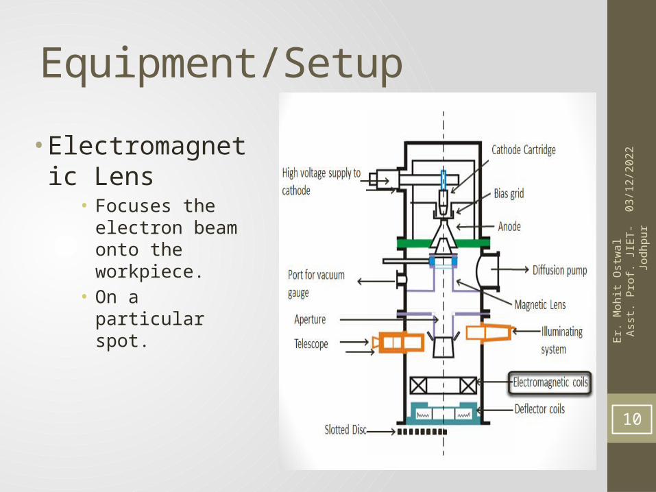
Equipment/Setup
• Electromagnetic Lens
• Focuses the electron beam onto the workpiece.
• On a particular spot.
10
05/0
2/20
23Er
. Moh
it O
stw
al
Asst
. Pro
f. JIE
T-Jo
dhpu
r
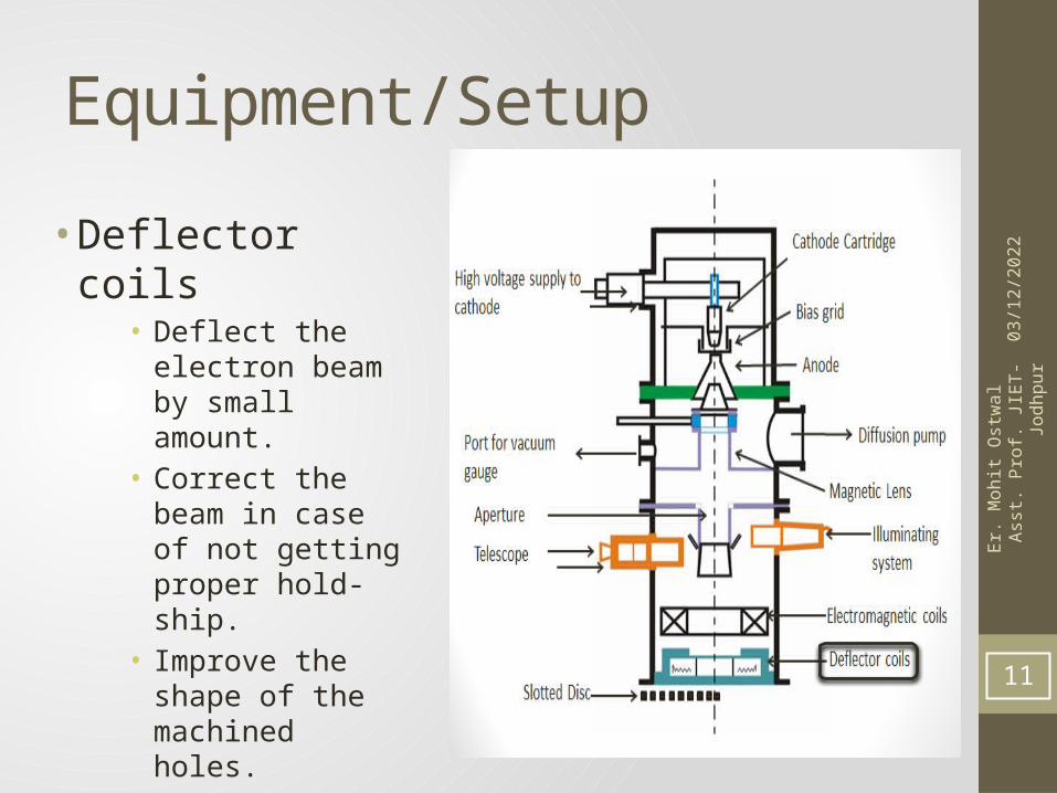
Equipment/Setup
• Deflector coils• Deflect the electron
beam by small amount.
• Correct the beam in case of not getting proper hold-ship.
• Improve the shape of the machined holes.
11

05/0
2/20
23Er
. Moh
it O
stw
al
Asst
. Pro
f. JIE
T-Jo
dhpu
r
Equipment/Setup
• Illuminating system & Telescope
• Both are used simultaneously to align the electron beam with the workpiece.
12

05/0
2/20
23Er
. Moh
it O
stw
al
Asst
. Pro
f. JIE
T-Jo
dhpu
r
Equipment/Setup
• Slotted Disc• To avoid obstruction
of vapor of metal into the optical window of EBM.
• Allow Electron beam to pass but not the vapors/metal fumes to pass through it.
• Synchronized with the pulsed beam.
13
05/0
2/20
23Er
. Moh
it O
stw
al
Asst
. Pro
f. JIE
T-Jo
dhpu
r
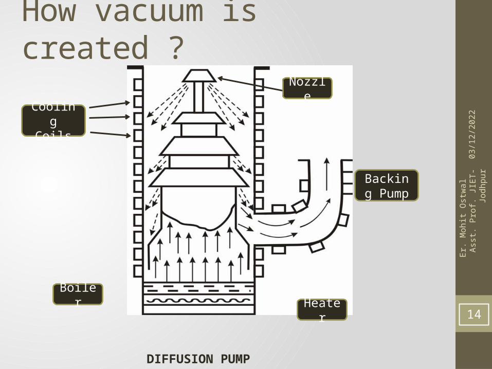
How vacuum is created ?
DIFFUSION PUMP
Heater
Backing Pump
Boiler
Nozzle
Cooling Coils
14
05/0
2/20
23Er
. Moh
it O
stw
al
Asst
. Pro
f. JIE
T-Jo
dhpu
r
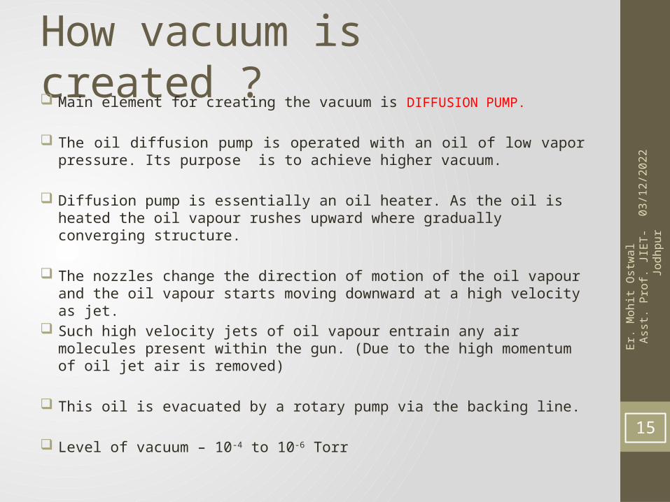
How vacuum is created ? Main element for creating the vacuum is DIFFUSION PUMP.
The oil diffusion pump is operated with an oil of low vapor pressure. Its purpose is to achieve higher vacuum.
Diffusion pump is essentially an oil heater. As the oil is heated the oil vapour rushes upward where gradually converging structure.
The nozzles change the direction of motion of the oil vapour and the oil vapour starts moving downward at a high velocity as jet.
Such high velocity jets of oil vapour entrain any air molecules present within the gun. (Due to the high momentum of oil jet air is removed)
This oil is evacuated by a rotary pump via the backing line.
Level of vacuum – 10-4 to 10-6 Torr 15
05/0
2/20
23Er
. Moh
it O
stw
al
Asst
. Pro
f. JIE
T-Jo
dhpu
r
Mechanism of material removal• As high voltage is applied across the Cathode filament ,
thermo-ionic emission of electrons takes place.• These Thermo-ionic electrons are replied by the cathode and
attracted by anode through the bias grid, electrons are accelerated to the half of the velocity of the light.
• These electron/beam of electron is shaped and focused with the help of series of magnetic and electromagnetic lenses.
• Finally the electron beam impinges the workpiece.• Upon impingement the kinetic energy of the electron is
absorbed by the workpiece which will result into heating, melting and vaporization – drilling.
• Spot size – 10 to 100 microns – high energy density 16
05/0
2/20
23Er
. Moh
it O
stw
al
Asst
. Pro
f. JIE
T-Jo
dhpu
r
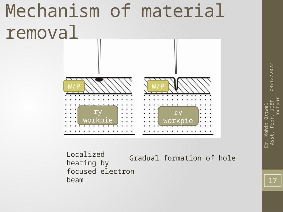
Mechanism of material removal
Localized heating by focused electron beam
Gradual formation of hole
Auxiliary workpiece
Auxiliary workpiece
W/P W/P
17
05/0
2/20
23Er
. Moh
it O
stw
al
Asst
. Pro
f. JIE
T-Jo
dhpu
r
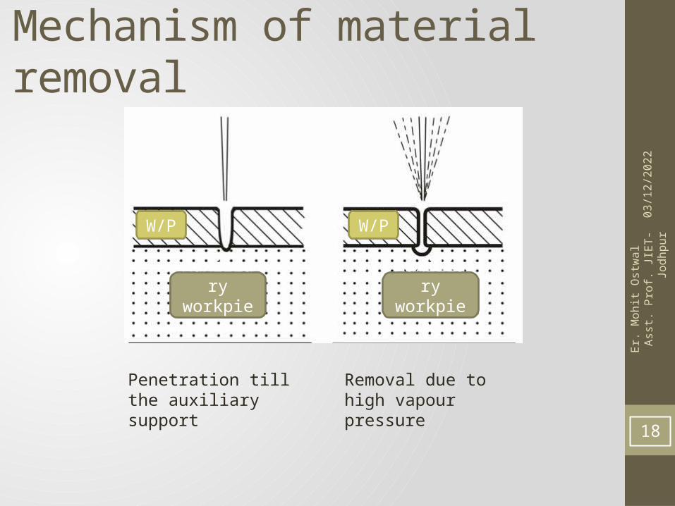
Mechanism of material removal
Penetration till the auxiliary support
Removal due to high vapour pressure
Auxiliary workpiece
W/P
Auxiliary workpiece
W/P
18
05/0
2/20
23Er
. Moh
it O
stw
al
Asst
. Pro
f. JIE
T-Jo
dhpu
r
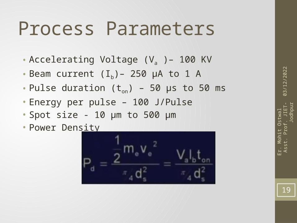
Process Parameters
• Accelerating Voltage (Va )– 100 KV
• Beam current (Ib)– 250 μA to 1 A
• Pulse duration (ton) – 50 μs to 50 ms• Energy per pulse – 100 J/Pulse• Spot size - 10 μm to 500 μm• Power Density
19
05/0
2/20
23Er
. Moh
it O
stw
al
Asst
. Pro
f. JIE
T-Jo
dhpu
r
Process capabilities• EBM can provide holes of diameter in the range of 100 μm to 2 mm
with a depth upto 15 mm, i.e., with a l/d ratio of around 10. • The hole can be tapered along the depth or barrel shaped. By focusing
the beam below the surface a reverse taper can also be obtained. • Generally burr formation does not occur in EBM. • A wide range of materials such as steel, stainless steel, Ti and Ni super-
alloys, aluminium as well as plastics, ceramics, leathers can be machined successfully using electron beam. Typically the heat-affected zone is around 20 to 30 μm.
• Some of the materials like Al and Ti alloys are more readily machined compared to steel.
• EBM does not apply any cutting force on the workpieces. Thus very simple work holding is required. This enables machining of fragile and brittle materials by EBM. Holes can also be drilled at a very shallow angle of as less as 20 to 300.
20
05/0
2/20
23Er
. Moh
it O
stw
al
Asst
. Pro
f. JIE
T-Jo
dhpu
r
Advantages EBM provides very high drilling rates when small holes with
large aspect ratio are to be drilled.
Moreover it can machine almost any material irrespective of their mechanical properties. As it applies no mechanical cutting force, work holding and fixturing cost is very less.
Further for the same reason fragile and brittle materials can also be processed. The heat affected zone in EBM is rather less due to shorter pulses.
21
05/0
2/20
23Er
. Moh
it O
stw
al
Asst
. Pro
f. JIE
T-Jo
dhpu
r
Disadvantages The primary limitations are the high capital cost of the
equipment and necessary regular maintenance applicable for any equipment using vacuum system.
Moreover in EBM there is significant amount of non-productive pump down period for attaining desired vacuum.
22
05/0
2/20
23Er
. Moh
it O
stw
al
Asst
. Pro
f. JIE
T-Jo
dhpu
r
Application
1. Drilling
2. Perforating of sheet
3. Pattern generation (associated with integrated circuit fabrication)
23