![PnC TECH BUSAN[1] · 2017. 4. 11. · DVS 2207-11 Welding of thermoplastics – heated tool welding of pipes, piping parts and panels made of PP DVS 2210-1 Industrial Pipelines made](https://static.fdocuments.in/doc/165x107/60c806bfba444f40b5261c94/pnc-tech-busan1-2017-4-11-dvs-2207-11-welding-of-thermoplastics-a-heated.jpg)
Electromagnetic welding: an advance in thermoplastics assembly
5
Electromagnetic welding: an, advance in thermoplastics assembly Peter Sanders, Emabond Europe BV, Canadalaan 8, 4631 NV Hoogerheide, The Netherlands Abstract The bonding process employs the principle of induction heating to produce rapid, reliable, positive seals on thermosplatics. Almost all thermoplastic materials are capable of being chemicallyjoined to each other as long as thejoining materials are compatible with each other in the melt state. A variety of dissimilar materials can also be welded by this process. Mechanical linkage of dissimilar materials can be accomplished via joint designs. Technical information is given about the process and several applications discussed. Introduction Although electromagnetic welding has been used in the USA for more than a decade, it is still relatively unfamiliar in Europe. Yet it is an important extension to the range of methods available to the engineering designer for the processing and assembly of thermoplastics. The designer of a thermoplastics assembly has a basic aim to use the opportunities for complex shaping presented by the injection moulding process to reduce the number of components to a minimum- ideally one. However, there remain many situations in which it is necessary to join thermoplastic components one to another: whether for reasons of configuration, sheer size, or the desire to make the assembly from more than one polymeric material. The fundamental thermoplastic characteristic of melting when heated and resolidifying in an unaltered state on cooling opens opportunities for joining parts by fusion. Such an integral weld tends to be stronger than a bond produced by the use of adhesives or by mechanical means. Fig. 1 summarises the thermoplastics welding methods that are in commercial use. They fall into three categories: thermal, frictional and electromagnetic. The thermal methods involve either the direct application of the thermo- plastic materials to the surface of a heated platen (hot-plate welding) or the use of a torch (hot-gas welding). The frictional techniques rely on the generation of heat by the physical abrasion of two faces held tightly together, movement being created by ultrasonic or mechanical vibration, or relative rotation of the parts. THERMOPLASTICS WELDING METHODS I I I FRICTION ~ THERMAL '~ ELECTROMAGNETIC I I I ULTRASON. ILl SPIN ~ VIBRATION HOT PLATE 1 HOT GAS Fig. 1 Thermoplastics welding methods used commercially. In electromagnetic (EM) welding, high-frequency inductive heating is used to heat a preformed, magnetically active welding material which is placed between the parts to be joined: this itself has a thermoplastic matrix which is chosen to suit the material or materials concerned. The extra cost of the EM welding material, which as described below is available in a variety of shapes and forms, is balanced by close control of the process; enhanced design opportunities; the quality of the seal that can be obtained; and the possibilities of achieving combinations of thermoplastic materials that cannot be welded by any other method. The heat is created precisely where it is needed, without setting up thermal stresses in the body of the assembly. Further, the EM welding preform also adds resin in the joint area - particularly useful where filled or composite thermoplastics are being joined. The EM welding process The principle is simple. A high- (radio-) frequency alternating current is applied to a thermoplastic matrix filled with a ferromagnetic powder which instantly heats up to the point of fusion through hysteresis and eddy current heat losses. When this material is placed between adjoining thermoplastic parts, they are also melted by conducted heat and fuse. The technique is fast and reliable: in practice, the time to fusion ranges from a few seconds for small assemblies to 30-60 seconds if large parts (where the bond line may be as long as 400cm) are being welded. Four basic components comprise the equipment needed for the Emaweld process: (Fig, 2). The generator converts a MATERIALS & DESIGN Vol. 8 No. 1 JANUARY/FEBRUARY 1987 41
-
Upload
peter-sanders -
Category
Documents
-
view
216 -
download
3
Transcript of Electromagnetic welding: an advance in thermoplastics assembly

Electromagnetic welding: an, advance in thermoplastics assembly
Peter Sanders, Emabond Europe BV, Canadalaan 8, 4631 NV Hoogerheide, The Netherlands
Abstract The bonding process employs the principle of induction heating to produce rapid, reliable, positive seals on thermosplatics. Almost all thermoplastic materials are capable of being chemically joined to each other as long as the joining materials are compatible with each other in the melt state. A variety of dissimilar materials can also be welded by this process. Mechanical linkage of dissimilar materials can be accomplished via joint designs. Technical information is given about the process and several applications discussed.
Introduction Although electromagnetic welding has been used in the USA for more than a decade, it is still relatively unfamiliar in Europe. Yet it is an important extension to the range of methods available to the engineering designer for the processing and assembly of thermoplastics. The designer of a thermoplastics assembly has a basic aim to use the opportunities for complex shaping presented by the injection moulding process to reduce the number of components to a minimum- ideally one. However, there remain many situations in which it is necessary to join thermoplastic components one to another: whether for reasons of configuration, sheer size, or the desire to make the assembly from more than one polymeric material.
The fundamental thermoplast ic characteristic of melting when heated and resolidifying in an unaltered state on cooling opens opportunities for joining parts by fusion. Such an integral weld tends to be stronger than a bond produced by the use of adhesives or by mechanical means. Fig. 1 summarises the thermoplastics welding methods that are in commercial use. They fall into three categories: thermal, frictional and electromagnetic.
The thermal methods involve either the direct application of the thermo- plastic materials to the surface of a heated platen (hot-plate welding) or the use of a torch (hot-gas welding). The frictional techniques rely on the generation of heat by the physical abrasion of two faces held tightly together, movement being created by ultrasonic or mechanical vibration, or relative rotation of the parts.
THERMOPLASTICS WELDING METHODS
I I I FRICTION ~ THERMAL ' ~ ELECTROMAGNETIC
I I I ULTRASON. ILl SPIN ~ VIBRATION HOT PLATE 1 HOT GAS
Fig. 1 Thermoplastics welding methods used commercially.
In electromagnetic (EM) welding, high-frequency inductive heating is used to heat a preformed, magnetically active welding material which is placed between the parts to be joined: this itself has a thermoplastic matrix which is chosen to suit the material or materials concerned. The extra cost of the EM welding material, which as described below is available in a variety of shapes and forms, is balanced by close control of the process; enhanced design opportunities; the quality of the seal that can be obtained; and the possibilities of achieving combinations of thermoplastic materials that cannot be welded by any other method. The heat is created precisely where it is needed, without setting up thermal stresses in the body of the assembly. Further, the EM welding preform also adds resin in the joint area - particularly useful where
filled or composite thermoplastics are being joined.
The EM welding process The principle is simple. A high- (radio-) frequency alternating current is applied to a thermoplastic matrix filled with a ferromagnetic powder which instantly heats up to the point of fusion through hysteresis and eddy current heat losses. When this material is placed between adjoining thermoplastic parts, they are also melted by conducted heat and fuse. The technique is fast and reliable: in practice, the time to fusion ranges from a few seconds for small assemblies to 30-60 seconds if large parts (where the bond line may be as long as 400cm) are being welded.
Four basic components comprise the equipment needed for the Emaweld process: (Fig, 2). The generator converts a
MATERIALS & DESIGN Vol. 8 No. 1 JANUARY/FEBRUARY 1987 41

50 Hz supply to a 3-10 MHz output with a power of l-5kW, depending on the application. The ferromagnetic particles are thus exposed to many oscillations per second and reach fusion temperature rapidly: it may be noted for comparison that the induction heating of solid metal parts for annealing or heat-treatment normally requires a frequency of only 200-500kHz. The induction coils are made from round, square or rectangular copper tubing or machined copper plates and are water-cooled. They are designed to develop the required intensity and uniformity of the magnetic field created to heat up the EM welding material. The proper design of these 'work coils' is the key to successful bonding; a number of types is available, as described below.
One of the two placement nests for the work coils is generally fixed and the other movable: they are normally constructed from electrically non- conductive materials because, if metal were used near the work coils, it would reduce the intensity of the magnetic flux. The placement nests are often built in the form of a light clamp or press. The E M welding material consists of a ferromagnetic filler distributed in a thermoplastic matrix. The filler consists of fine, micron-sized particles of iron, stainless steel or other magnetic materials: formulations meeting Food and Drugs Administration (FDA) requirements are available if needed. The filler type, concentration and particle size determine the process cycle time.
The matrix is usually based on the thermoplastic materials to be joined, whose melt indices may also need to be matched. Where dissimilar materials are being welded, a blend of the two polymers in question is used to formulate the matrix. Fig 3 shows that the Emaweld process can be used to bond almost all thermoplastics to each other, as well as for many dissimilar pairs.
Both the size and the shape of the components and optimum positioning of the work coils determine the type and cross section of the EM welding material. Emaweld material is supplied in a number of forms: as strands and extruded profiles; in tapes and strips up to 30cm wide; and as stampings and injection-moulded parts. The precise shape as well as the formulation to be used needs the most careful consideration, and the production of a custom-made material may well prove desirable to ensure maximum efficiency. Profiles often offer the most economical solution and wide variety is available either on continous reels or precut.
Systems can be designed for in-line
Fig. 2 The basic components of the EM welding process.
Indu
Almost all thermoplastics can be welded by the EMAWELD TM
process
0 = Compatible
ABS Acetals Acrylic Cellulosics Ionomer (Surlyn) Nylon 6.6, 11,12 Polybutylene Polycarbonate Polyethylene Polyphenylene Oxide (Noryl) Polypropylene Polystyrene Polysulphone Polyvinyt Chloride Polyurethane SAN Thermoplastic Polyester Thermo- ~ Plastic ~ C o p o l y m e Elastomers I Otefin Type
Note the indication of which dissimilar thermoplastics can be welded, ABS/Acrylic and ABS / Polycarbonate, for example.
Fig 3 Similar and dissimilar thermoplastics that can be bonded by EM welding
42 MATERIALS & DESIGN Vol. 8 No. 1 JANUARY/FEBRUARY 1987

or rotary high-production sealing lines. In these, the latest technology including programmable controllers is incorporated; a sealing rate of up to 150 parts per minute can be achieved, leading to high cost-effectiveness.
The welding process The principle of the EM welding process is illustrated in Fig. 4, as applied to a tongue-and-groove joint. Before welding, the EM material is placed in the groove of one of the parts to be joined and the tongue of the other is inserted to enclose it. The coil is then activated and the material starts to melt, at the same time conducting its heat to the adjacent surfaces. This is preferably done under light pressure (0.1 - 0.3N/mm2). The molten EM material flows along the path of least resistance to fill completely the space between tongue and groove over a large surface area with which it forms an integral bond. Bond strength is proportional to the surface area of contact. It is also important for a tight and/or strong weld to ensure that the flow of molten material is well contained.
As in injection moulding, the amount of molten material needed to fill the cavity can be accurately calculated to avoid wastage. The formula used is: A E = k.Av where A E is the cross-sectional area of
the E M welding material, A v is the cross-sectional area of the cavity between the parts to be filled, k is a constant ranging from 1.02
- 1.05 (depending on the pressure used).
The k factor is to allow for overfill to ensure that any irregularit ies are adequately dealt with, producing reliable and continuous welds with near-zero reject rates.
Joint Design Good joint design is crucial to the successful performance of the weld. Five basic types of joint are shown in Fig 5. (a) A fiat-to-fiat joint is the simplest design, well suited for continuous welding operations or for parts with a long weld line. (b) A fiat-to-groove joint ensures accurate positioning of the weld and is used where this is critical, such as in the manufacture of auto- motive panels. It also ensures that the EM material is well contained, giving a bond with a high degree of structural integrity. (c) Tongue-and-groove joints provide the highest strength, with the weld line including the whole surface area of the tongue. Complete contain- ment of the EM material makes this
before welding during welding after welding
Fig. 4 The principle of the EM welding process (tongue-and-groove joint).
JOINT BEFORE AFTER
FLAT- (a) TO- ~ I I
FLAT ~ ~'
FLAT- (b) TO- ~ II~
GROOVE I - - I
TONGUE- ~ ~ ] (c) AND- I~
GROOVE
(d) SHEAR
(e) STEP
Fig. 5 Five basic types of EM-welded joint.
MATERIALS & DESIGN Vol. 8 No. 1 JANUARY/FEBRUARY 1987 43

type particularly suitable where a pressure-tight or hermetic weld is required. Such a weld is often also invaluable where design aesthetics are important- eg in transparent assemblies. (d) A shear joint as shown is often used for high-pressure container seals: the weld can be designed to withstand pressure either from inside or outside the vessel. A weld in shear to the applied forces has the greatest strength. (e) The step joint is a modification of (d), also excellent for containing pressure. Such a joint can accommodate wide variations in part shrinkage. Fig. 6 shows four examples of actual joint configurations. In (b), it can be seen that a k factor of 1.04 has been applied, while in (d) the tongues of two components are joined in a double groove in a third: all three components are welded together in a single cycle.
Coils The proper design of the work coils forms the heart of the knowhow essential for successful welding, Each application requires analysis before the best solution can be recommended and, if necessary, the production of special coil sets. Some basic coil designs are shown in Fig 7. The simplest form is a single- turn coil, which has a magnetic field concentrated around its inner diameter. A multi-turn coil extends the magnetic field and, when part dimensions interfere with coil location, can penetrate a more remote weld area: the number of turns depends on the total surface area of the weld. Pancake coils are mainly used for heating large flat areas. They are made by winding tubing in a horizontal plane until the predetermined diameter is reached. In a hairpin coil, a single-turn coil is in effect squeezed to enable the magnetic field to be highly concentrated. Two such coils may be placed on either side of a thin weld to give very accurate localised heating.
Uniqueness The capability of the Emaweld process for welding large parts (up to 600cm bond line in one shot) gives it a major advantage over other assembly techniques. Such thermoplastic parts are difficult to mould 'straight and square', so that tolerances must be generous. This often causes problems where frictional welding methods are used because, where contact between the mating faces is lost, there can be no weld. EM welding overcomes this problem as the Emaweld material fills the voids between the components to be welded. In this way, surface imperfections or tolerances in the moulded components are allowed for;, which is
"•• 0.9 1.1 1 LL ~
~ 4.~9JI Before i4.71 After
(a) (b)
4.1 ~ -~ 413 1.0,~- 0.~_ 0 . 4 3 _0 .43
Before After (c) Before After (d)
Fig. 6 Practical examples of EM-welded joint configurations.
Single-+,,~n Multi-turn
Fig. 7 Basic designs of work coil.
why the Emaweld process is considered to be very "forgiving".
Further, with joints in more than one plane, the generation of sufficient heat by friction heating becomes very difficult or even impossible. Irregular or contoured welds in different planes are readily obtained by the EM technique - as, for example, in the assembly of a box- section car bumper beam, where a total bond length of 500cm has been welded with a heating cycle of 15 seconds.
A side benefit of the EM process is that, if desired, the bond line can be reactivated and the weld separated. For
instance, a damaged fitting from an expensive drum could be replaced by a new one, or a lid could be welded to a vessel containing a very expensive or aggressive substance to ensure safe transport, and 'unwelded' on delivery.
In filled or composite thermoplastic materials, that part of the surface where resin has been replaced by an inert substance clearly presents a problem with most conventional welding techniques, since them is insufficient fusible material in some areas. The EM welding material here fulfils a double purpose: not only is it the source of heat but it also provides
44 MATERIALS & DESIGN VoI. 8 No. 1 JANUARY/FEBRUARY 1987
extra material where it is needed to ensure an effective bond.
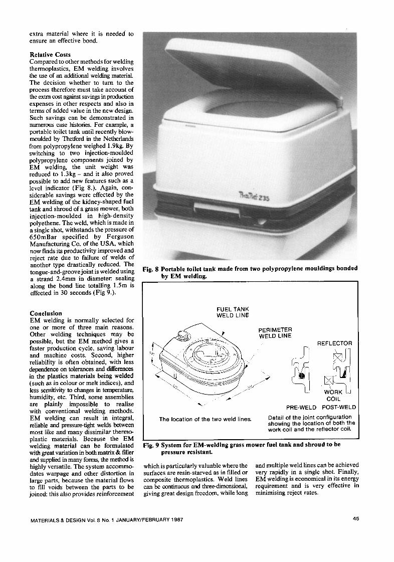
Relative Costs Compared to other methods for welding thermoplastics, EM welding involves the use of an additional welding material. The decision whether to turn to the process therefore must take account of the extra cost against savings in production expenses in other respects and also in terms of added value in the new design. Such savings can be demonstrated in nurnerous case histories. For example, a portable toilet tank until recently blow- moulded by Thefford in the Netherlands from polypropylene weighed 1.9kg. By switching to two injection-moulded polypropylene components joined by EM welding, the unit weight was reduced to 1 .3kg- and it also proved possible to add new features such as a level indicator (Fig 8.). Again, con- siderable savings were effected by the EM welding of the kidney-shaped fuel tank and shroud of a grass mower, both injection-moulded in high-density polyethene. The weld, which is made in a single shot, withstands the pressure of 650mBar specified by Ferguson Manufacturing Co. of the USA, which now finds its productivity improved and reject rate due to failure of welds of another type drastically reduced. The tongue-and-groove joint is welded using a strand 2.4mm in diameter, sealing along the bond line totalling 1.5m is effected in 30 seconds (Fig 9.).
Conclusion EM welding is normally selected for one or more of three main reasons. Other welding techniques may be possible, but the EM method gives a faster production cycle, saving labour and machine costs. Second, higher reliability is often obtained, with less dependence on tolerances and differences in the plastics materials being welded (such as in colour or melt indices), and less sensitivity to changes in temperature, humidity, etc. Third, some assemblies are plainly impossible to realise with conventional welding methods. EM welding can result in integral, reliable and pressure-fight welds between most like and many dissimilar thermo- plastic materials. Because the EM welding material can be formulated with great variation in both matrix & filler and supplied in many forms, the method is highly versatile. The system accommo- dates warpage and other distortion in large parts, because the material flows to fill voids between the parts to be joined: this also provides reinforcement
Fig. 8 Portable toilet tank made from two polypropylene mouldings bonded by EM welding.
FUEL TANK WELD LINE
The location of the two weld lines.
PERIMETER WELD LINE
PRE-WELD
REFLECTOR
COIL
POST-WELD
Detail of the joint conf igurat ion showing the location of both the work coil and the ref lector coil.
Fig. 9 System for EM-welding grass mower fuel tank and shroud to be pressure resistant.
which is particularly valuable where the surfaces are resin-starved as in filled or composite thermoplastics. Weld lines can be continuous and three-dimensional, giving great design freedom, while long
and multiple weld lines can be achieved very rapidly in a single shot. Finally, EM welding is economical in its energy requirement and is very effective in minimising reject rates.
MATERIALS & DESIGN Vol. 8 No. 1 JANUARY/FEBRUARY 1987 45