Electromagnetic Interference Shielding Polymers and ... · REVIEW Electromagnetic Interference...
59
Full Terms & Conditions of access and use can be found at https://www.tandfonline.com/action/journalInformation?journalCode=lmsc20 Polymer Reviews ISSN: 1558-3724 (Print) 1558-3716 (Online) Journal homepage: https://www.tandfonline.com/loi/lmsc20 Electromagnetic Interference Shielding Polymers and Nanocomposites - A Review Dawei Jiang, Vignesh Murugadoss, Ying Wang, Jing Lin, Tao Ding, Zicheng Wang, Qian Shao, Chao Wang, Hu Liu, Na Lu, Renbo Wei, Angaiah Subramania & Zhanhu Guo To cite this article: Dawei Jiang, Vignesh Murugadoss, Ying Wang, Jing Lin, Tao Ding, Zicheng Wang, Qian Shao, Chao Wang, Hu Liu, Na Lu, Renbo Wei, Angaiah Subramania & Zhanhu Guo (2019): Electromagnetic Interference Shielding Polymers and Nanocomposites - A Review, Polymer Reviews, DOI: 10.1080/15583724.2018.1546737 To link to this article: https://doi.org/10.1080/15583724.2018.1546737 Published online: 08 Feb 2019. Submit your article to this journal Article views: 13 View Crossmark data
Transcript of Electromagnetic Interference Shielding Polymers and ... · REVIEW Electromagnetic Interference...
Full Terms & Conditions of access and use can be found athttps://www.tandfonline.com/action/journalInformation?journalCode=lmsc20
Polymer Reviews
ISSN: 1558-3724 (Print) 1558-3716 (Online) Journal homepage: https://www.tandfonline.com/loi/lmsc20
Electromagnetic Interference Shielding Polymersand Nanocomposites - A Review
Dawei Jiang, Vignesh Murugadoss, Ying Wang, Jing Lin, Tao Ding, ZichengWang, Qian Shao, Chao Wang, Hu Liu, Na Lu, Renbo Wei, AngaiahSubramania & Zhanhu Guo
To cite this article: Dawei Jiang, Vignesh Murugadoss, Ying Wang, Jing Lin, Tao Ding, ZichengWang, Qian Shao, Chao Wang, Hu Liu, Na Lu, Renbo Wei, Angaiah Subramania & Zhanhu Guo(2019): Electromagnetic Interference Shielding Polymers and Nanocomposites - A Review, PolymerReviews, DOI: 10.1080/15583724.2018.1546737
To link to this article: https://doi.org/10.1080/15583724.2018.1546737
Published online: 08 Feb 2019.
Submit your article to this journal
Article views: 13
View Crossmark data
REVIEW
Electromagnetic Interference Shielding Polymers andNanocomposites - A Review
Dawei Jianga�, Vignesh Murugadossb,c�, Ying Wanga, Jing Lind, Tao Dinge,Zicheng Wangb,f, Qian Shaog, Chao Wangh, Hu Liub, Na Luf, Renbo Weii,Angaiah Subramaniac, and Zhanhu Guob
aDepartment of Chemical Engineering and Technology, College of Science, Northeast ForestryUniversity, Harbin, China; bIntegrated Composites Laboratory (ICL), Department of Chemical andBiomolecular Engineering, University of Tennessee, Knoxville, TN, USA; cElectrochemical EnergyResearch Lab, Centre for Nanoscience and Technology, Pondicherry University, Puducherry, India;dDepartment of Chemical Engineering, School of Chemistry and Chemical Engineering, GuangzhouUniversity, Guangzhou, China; eDepartment of Chemistry, College of Chemistry and ChemicalEngineering, Henan University, Kaifeng, P. R. China; fDepartment of Civil Engineering, Lyles School ofCivil Engineering, School of Materials Engineering, Birck Nanotechnology Center, Purdue University,West Lafayette, IN, USA; gDepartment of Applied Chemistry, College of Chemical and EnvironmentalEngineering, Shandong University of Science and Technology, Qingdao, Shandong, China; hDepartmentof Materials Science and Engineering, College of Materials Science and Engineering, North University ofChina, Taiyuan, China; iDepartment of Chemistry, Research Branch of Advanced Functional Materials,University of Electronic Science and Technology of China, Chengdu, China
ABSTRACTIntrinsically conducting polymers (ICP) and conductive fillers incorpo-rated conductive polymer-based composites (CPC) greatly facilitatethe research in electromagnetic interference (EMI) shielding becausethey not only provide excellent EMI shielding but also have advan-tages of electromagnetic wave absorption rather than reflection.In this review, the latest developments in ICP and CPC basedEMI shielding materials are highlighted. In particular, existing meth-ods for adjusting the morphological structure, electric and magneticproperties of EMI shielding materials are discussed along with thefuture opportunities and challenges in developing ICP and CPC forEMI shielding applications.
ARTICLE HISTORYReceived 29 August 2018Accepted 2 October 2018
KEYWORDSAbsorption dominant;Conductive polymercomposites; Electromagneticinterference shielding;Intrinsically conductingpolymers; lightweightmaterials; Multi-component systems;
1. Introduction
Electromagnetic interference (EMI) has become a severe concern owing to rapid advancementin technology and widespread usage of electronic devices.1–3 Electromagnetic interference isan electromagnetic pollution caused by electromagnetic noise originated either from naturalsource (lighting, solar flares, etc.) or man-made devices (electrical circuit, electronic devices,
CONTACT Jing Lin [email protected] Department of Chemical Engineering, School of Chemistry and ChemicalEngineering, Guangzhou University, Guangzhou, China; Tao Ding [email protected] Department of Chemistry,College of Chemistry and Chemical Engineering, Henan University, Kaifeng, P. R. China; Renbo Wei [email protected]
Department of Chemistry, Research Branch of Advanced Functional Materials, University of Electronic Science andTechnology of China, Chengdu, China; Zhanhu Guo [email protected] Integrated Composites Laboratory (ICL),Department of Chemical and Biomolecular Engineering, University of Tennessee, Knoxville 37996, TN, USA.�Dawei Jiang and Vignesh Murugadoss contributed equally and should be treated as the co-first authors.Color versions of one or more of the figures in the article can be found online at www.tandfonline.com/lmsc� 2019 Taylor & Francis Group, LLC
POLYMER REVIEWShttps://doi.org/10.1080/15583724.2018.1546737
etc.) over a frequency range (depends on the source) that affects or degrades the performanceof another electronic device/electrical circuit and loss of stored data.4 The disturbance may becaused by electromagnetic coupling, electromagnetic induction or conduction. Anthropogenicelectromagnetic noise also affects biological processes, including human health.5,6 Thesemajor issues have spurred researchers to develop materials for EMI shielding (or EMIattenuation), having a broad range of applications ranging from the electronic systemsto biological systems.7–10 In order to avoid serious problems of EMI, some organizationshave standardized electromagnetic compatibility (EMC) regulations.11 Electromagneticcompatibility refers to the ABILITY OF AN EQUIPMENT or an EMI shielding material thatdoes not affect itself or any other equipment due to EM radiation.12,13
The usage of traditional metal and metallic composites as an EMI shielding materials isrestricted by their high density, poor mechanical flexibility, corrosiveness, and tedious andexpensive processing costs. Hence, the advanced EMI shielding materials are now mainlyfocused on carbon matrix, polymeric matrix, and ceramic matrix composites.14–24 Thenecessities for a standard EMI shielding material are high electrical conductivity, excellentthermal stability, and low density.25–27 Carbon nanostructures have extended their interestsover metals due to their good electrical conductivity, corrosion resistance, and flexibil-ity.28,29 Even though carbon nanostructures suffer from high cost, tedious synthesis proce-dures, and poor EM absorption properties, the dielectric loss of carbon nanostructures isascribed to electron polarization rather than natural resonance and Debye dipolar relax-ation. Also, their high electron mobility causes considerable skin effect on EM wave irradi-ation. It has been reported that the addition of polymers to the carbon nanostructures canovercome these limitations and improve their EM absorption properties.30–33 For example,Yu et al. demonstrated that deposition of polyaniline (PANI) nanoarray onto the grapheneimproved their EM absorption.34 Bera et al. demonstrated that the electromagnetic waveabsorption of the FRS [Fe3O4 coated reduced graphene oxide (RGO)/single wall carbonnanohorn (SWCNH)] was increased after incorporation into polydimethylsiloxane (PDMS)matrix. The dipole polarization and interfacial polarization along with the reduction in sur-face reflectivity due to skin effect contributed to this enhanced EM absorption.35
In that context, the intrinsic conducting polymers (ICP) and the conductive polymercomposites (CPC) (insulating polymers filled with conducting fillers) play an importantrole in the development of commercially viable EMI shielding materials.36–38
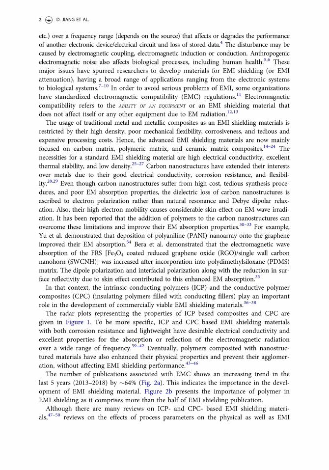
The radar plots representing the properties of ICP based composites and CPC aregiven in Figure 1. To be more specific, ICP and CPC based EMI shielding materialswith both corrosion resistance and lightweight have desirable electrical conductivity andexcellent properties for the absorption or reflection of the electromagnetic radiationover a wide range of frequency.39–42 Eventually, polymers composited with nanostruc-tured materials have also enhanced their physical properties and prevent their agglomer-ation, without affecting EMI shielding performance.43–46
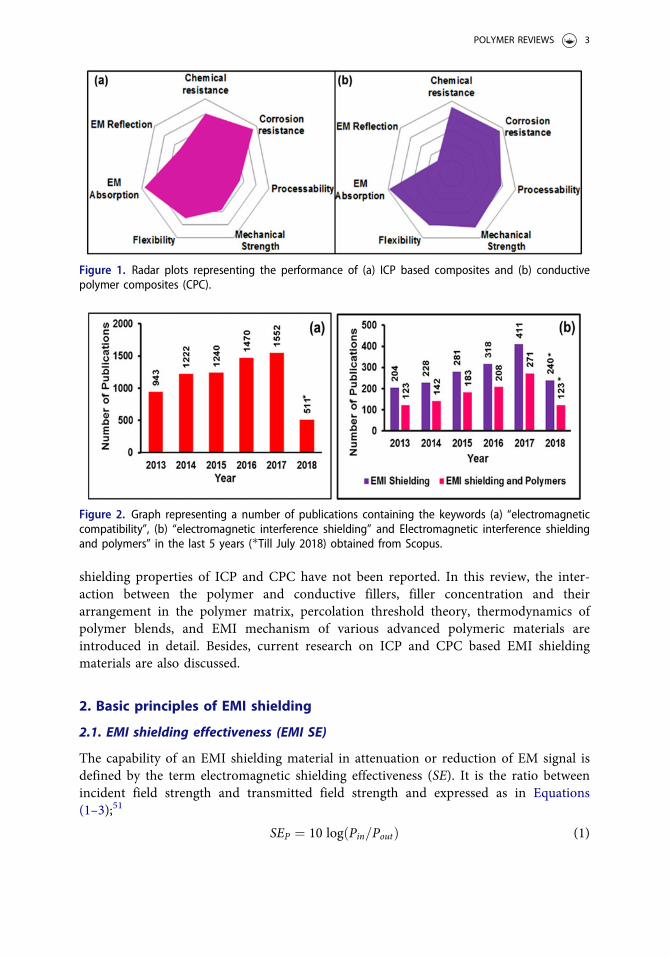
The number of publications associated with EMC shows an increasing trend in thelast 5 years (2013–2018) by �64% (Fig. 2a). This indicates the importance in the devel-opment of EMI shielding material. Figure 2b presents the importance of polymer inEMI shielding as it comprises more than the half of EMI shielding publication.Although there are many reviews on ICP- and CPC- based EMI shielding materi-
als,47–50 reviews on the effects of process parameters on the physical as well as EMI
2 D. JIANG ET AL.
shielding properties of ICP and CPC have not been reported. In this review, the inter-action between the polymer and conductive fillers, filler concentration and theirarrangement in the polymer matrix, percolation threshold theory, thermodynamics ofpolymer blends, and EMI mechanism of various advanced polymeric materials areintroduced in detail. Besides, current research on ICP and CPC based EMI shieldingmaterials are also discussed.
2. Basic principles of EMI shielding
2.1. EMI shielding effectiveness (EMI SE)
The capability of an EMI shielding material in attenuation or reduction of EM signal isdefined by the term electromagnetic shielding effectiveness (SE). It is the ratio betweenincident field strength and transmitted field strength and expressed as in Equations(1–3);51
SEP ¼ 10 log Pin=Poutð Þ (1)
Figure 1. Radar plots representing the performance of (a) ICP based composites and (b) conductivepolymer composites (CPC).
Figure 2. Graph representing a number of publications containing the keywords (a) “electromagneticcompatibility”, (b) “electromagnetic interference shielding” and Electromagnetic interference shieldingand polymers” in the last 5 years (�Till July 2018) obtained from Scopus.
POLYMER REVIEWS 3
SEE ¼ 20 log Ein=Eoutð Þ (2)
SEH ¼ 20 log Hin=Houtð Þ (3)
where P, E, and H are the strength of plane wave, electric field, and magnetic field, respect-ively of the EM wave. The subscripts in and out represent the magnitude of the fieldstrength that is incident on and transmitted through an EMI shielding material, respectively.EMI SE is expressed in decibels (dB). All electromagnetic waves include an electric (E) anda magnetic (H) fields orthogonal to each other. An EM wave propagates at a right angle tothe plane containing electric field and magnetic field, and its characteristics depend on theirfrequency and associated photon energies. The ratio between the electric field strength andthe magnetic field strength is called wave impedance. Based on the distance (r) of the EMIshielding material from an EM wave source, the region of measurement is separated intothe far-field and the near-field region. In the far-field region, where the distance betweenEM wave source and shielding material (r) is greater than k=2p, the ratio of the E to H(EM wave impedance) is equal to the intrinsic impedance of free space (Zo ¼ 377 X). Soin the far-field region, plane wave exists and SEE ¼ SEH . In the near-field region where r isless than k=2p, the EM wave impedance is not equal to the intrinsic impedance of the freespace. In this region, an EM wave is either electrical field dominant (large EM wave imped-ance) or magnetic field dominant (small EM wave impedance) that depends on its sourceand distance. If the EM wave impedance is higher than the Zo, then it is electric field dom-inant and vice-versa. Thus SEE 6¼ SEH . The transition point occurs where the distance isless than k=2p. The region of a transition is known as the transition region at which r isapproximately equal to k=2p.52,53
2.2. EMI shielding mechanism
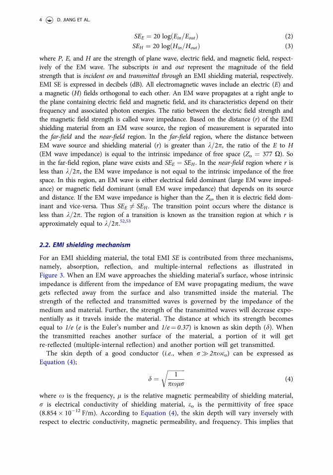
For an EMI shielding material, the total EMI SE is contributed from three mechanisms,namely, absorption, reflection, and multiple-internal reflections as illustrated inFigure 3. When an EM wave approaches the shielding material’s surface, whose intrinsicimpedance is different from the impedance of EM wave propagating medium, the wavegets reflected away from the surface and also transmitted inside the material. Thestrength of the reflected and transmitted waves is governed by the impedance of themedium and material. Further, the strength of the transmitted waves will decrease expo-nentially as it travels inside the material. The distance at which its strength becomesequal to 1/e (e is the Euler’s number and 1/e¼ 0.37) is known as skin depth (d). Whenthe transmitted reaches another surface of the material, a portion of it will getre-reflected (multiple-internal reflection) and another portion will get transmitted.The skin depth of a good conductor (i.e., when r� 2pxeo) can be expressed as
Equation (4);
d ¼ffiffiffiffiffiffiffiffiffiffiffiffi1
pxlr
r(4)
where x is the frequency, l is the relative magnetic permeability of shielding material,r is electrical conductivity of shielding material, eo is the permittivity of free space(8.854� 10�12 F/m). According to Equation (4), the skin depth will vary inversely withrespect to electric conductivity, magnetic permeability, and frequency. This implies that
4 D. JIANG ET AL.
an increase in the electric conductivity, magnetic permeability, and frequency increasesthe reflection rather than the absorption.54
Thus, the total SE of an EMI shielding material (SET) is the total of three SE contrib-uted from reflection (SER), absorption (SEA), and multiple-internal reflections (SEM) asdepicted in Equation (5);
SET ¼ SEA þ SER þ SEM (5)
The losses due to reflection and multiple-internal reflection mechanisms are the func-tion of impedance and hence their values are different for the electric field, magneticfield, and a plane wave. On contrary, absorption phenomenon does not depend on theimpedance and hence the absorption loss will have the same value for all these threefields.55 SEM is negligible when SEA is greater than 10 dB.
2.3. Properties governing EMI shielding mechanism
EMI shielding mechanisms of an EMI shielding material can be understood by measur-ing their dielectric (relative complex permittivity, er ¼ e0r � je00r ) and magnetic (relativecomplex permeability, lr ¼ l0r � jl00r ) properties.
56 The real parts e0r and l0r indicate thecharge storage and magnetic storage of the EM waves, whereas their imaginary parts e00r
Figure 3. Pictorial depiction of the EMI shielding mechanism and the skin depth of an EMI shieldingmaterial.
POLYMER REVIEWS 5
and l00r indicate dielectric loss and magnetic loss during the interaction with EM waves,respectively. The amount of losses can be calculated from the tangent of dielectric loss(tande ¼ e00r
e0r) and magnetic loss (tandl ¼ l00r
l0r).57
2.3.1. Dielectric propertyThe dielectric loss is mostly governed by ionic, orientational, electronic, and interfacialpolarization. The ionic and orientational polarization attributed to the bound charges inthe material. Interfacial polarization arises from space charges that mount up owing tothe dissimilarity in the electrical conductivity/dielectric constant at the interface of twodifferent materials, according to Maxwell-Wagner-Sillars (MWS) theory.58
The e0r and e00r can be related by the following Cole-Cole Equation (6);59
e0r�es þ e1
2
� �2
þ e00r� �2 ¼ es�e1
2
� �2
(6)
where es is the static dielectric constant and e1 is the relative dielectric constant.When the Cole-Cole plot is a semicircle, then the semicircle is related to a Debye
relaxation process. For composite materials, more than one semicircle or distorted semi-circle may be observed. These are attributed to more than one Debye relaxation andother mechanisms such as interfacial polarizations. For highly conducting materials,semicircle may not be observed, as the loss results mainly from conduction loss, whichcan be expressed as Equation (7);
e00r ¼r
2pxeo(7)
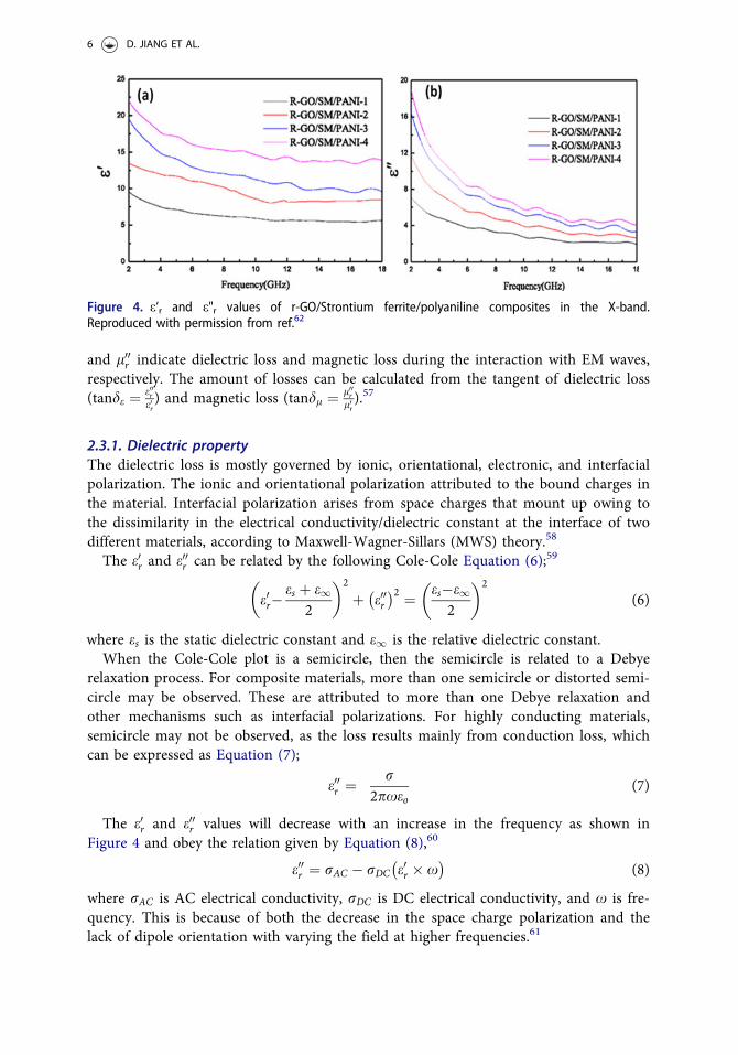
The e0r and e00r values will decrease with an increase in the frequency as shown inFigure 4 and obey the relation given by Equation (8),60
e00r ¼ rAC � rDC e0r � x� �
(8)
where rAC is AC electrical conductivity, rDC is DC electrical conductivity, and x is fre-quency. This is because of both the decrease in the space charge polarization and thelack of dipole orientation with varying the field at higher frequencies.61
Figure 4. e’r and e"r values of r-GO/Strontium ferrite/polyaniline composites in the X-band.Reproduced with permission from ref.62
6 D. JIANG ET AL.
2.3.2. Magnetic propertyThe magnetic loss arises from domain wall loss, hysteresis loss, eddy current loss, andresidual loss.63 The hysteresis loss results from the hysteresis (i.e., time lag of magnetiza-tion vector M, behind the magnetic field vector H), where magnetic energy is dissipatedas heat. The eddy current loss is expressed as Equation (9);64
Co ¼ l00r.
x: l0rð Þ2¼ 2p
3lorD
2 (9)
where lo is vacuum permeability and D is the diameter of the magnetic nanoparticle.The eddy current loss (Co) remains constant with changing the frequency. For highlyconducting materials, the eddy current loss is negligible and expressed as in Equation(10);
l00rl0r
/ l00r D2x
q(10)
where q is the electrical resistivity. The other losses include natural resonance andexchange resonance. The natural resonance usually occurs at a lower frequency andnano-sized particles will enhance the exchange resonance.65,66 Ferromagnetic resonancetheory states that the effective magnetic field (anisotropic energy) governs the naturalresonance as expressed in Equations (11 and 12);67
xr ¼ c2p
He (11)
He ¼ 4j13loMs
(12)
where c2p is the gyromagnetic ratio (equals to 28GHz T�1), He is the effective magnetic
field, j1 is magnetic crystalline anisotropy co-efficient for a magnetic material, andloMs is the saturation magnetization. A higher the effective magnetic field (Anisotropicenergy) favors a higher the EM wave absorption in the higher frequency range.68 Alower value of l0r (magnetic storage) than the value of l00r (magnetic loss) is desirable forthe absorption of EM wave.The reflection loss of a material depends on the mobile charge carriers. Reflection
does not need interconnected conducting filler network, but it possibly will improvewith the presence of the interconnected network. On the other hand, electric and mag-netic dipoles dominate the absorption loss. In absence of magnetic property, the EMIshielding depends solely on dielectric property and vice versa.69 Multiple-internal reflec-tions originate from the reflections at the interfaces and in-homogeneities of theshielded material.
2.4. EM absorption
Since the reflection loss causes secondary EM pollution, EMI shielding materials exhibit-ing strong absorption have attracted the research interests. For the EMI shielding mate-rials, SEA, SER, and SEM as a function of their electromagnetic properties can beexpressed as Equations (13–15);70
POLYMER REVIEWS 7
SEA ¼ 20dffiffiffiffiffiffiffiffiffiffiffirAC :=2
q(13)
SER ¼ 10 logrAC
16:eo:lr:x
� �(14)
SEM ¼ 20 log1�e�2dd : e�j2d (15)
where d is the distance traveled by the EM waves inside the EMI shielding material.The above Equations (13–15) imply that the reflection of an EMI shielding material is afunction of rAC
lrand will decrease with an increase in frequency, whereas the absorption
loss is a function rAC:lr and will increase with an increase in frequency. Multiple-internal reflection can be neglected for the EMI shielding materials whose thickness islarger than its skin depth (d).71 For a shielding material with a thickness less than thevalue of d, the multiple-internal reflection decreases the EMI SE. Their EMI SE willincrease with an increase in thickness.72
As per the transmission line theory, for an EMI shielding material having a perfectconductor at its back, reflection loss (RL) at its surface as a function of impedance isdefined as Equation (16),
RL dBð Þ ¼ 20logZin�Zo
Zin þ Zo
� �(16)
where Zin is the input impedance of the EMI shielding material at the surface and Zo isthe intrinsic impedance of free space (377 X). The Zin is given by Equation (17);
Zin ¼ffiffiffiffiffiffiffiffiffiffiffilr=er
ptanh j 2pxd=cð Þ ffiffiffiffiffiffiffiffiffi
lr:erp
(17)
where c is the velocity of light.EM absorption ability of an EMI shielding material can be confirmed by calculating
the attenuation constant (a) using Equation (18);
a ¼ffiffiffi2
ppxc
�ffiffiffiffiffiffiffiffiffiffiffiffiffiffiffiffiffiffiffiffiffiffiffiffiffiffiffiffiffiffiffiffiffiffiffiffiffiffiffiffiffiffiffiffiffiffiffiffiffiffiffiffiffiffiffiffiffiffiffiffiffiffiffiffiffiffiffiffiffiffiffiffiffiffiffiffiffiffiffiffiffiffiffiffiffiffiffiffiffiffiffie00l00�e0l0ð Þ þ
ffiffiffiffiffiffiffiffiffiffiffiffiffiffiffiffiffiffiffiffiffiffiffiffiffiffiffiffiffiffiffiffiffiffiffiffiffiffiffiffiffiffiffiffiffiffiffiffiffiffiffiffiffiffiffiffiffiffie00l00�e0l0ð Þ2 þ e00l00 þ e0l0ð Þ2
qr(18)
These above equations imply that to achieve good EMI absorbing materials, the fol-lowing two criteria needed be satisfied: (1) excellent impedance matching and (2) goodbalance between the dielectric loss (tande ¼ e00
�e0) and magnetic loss (tandl ¼ l00
�l0).
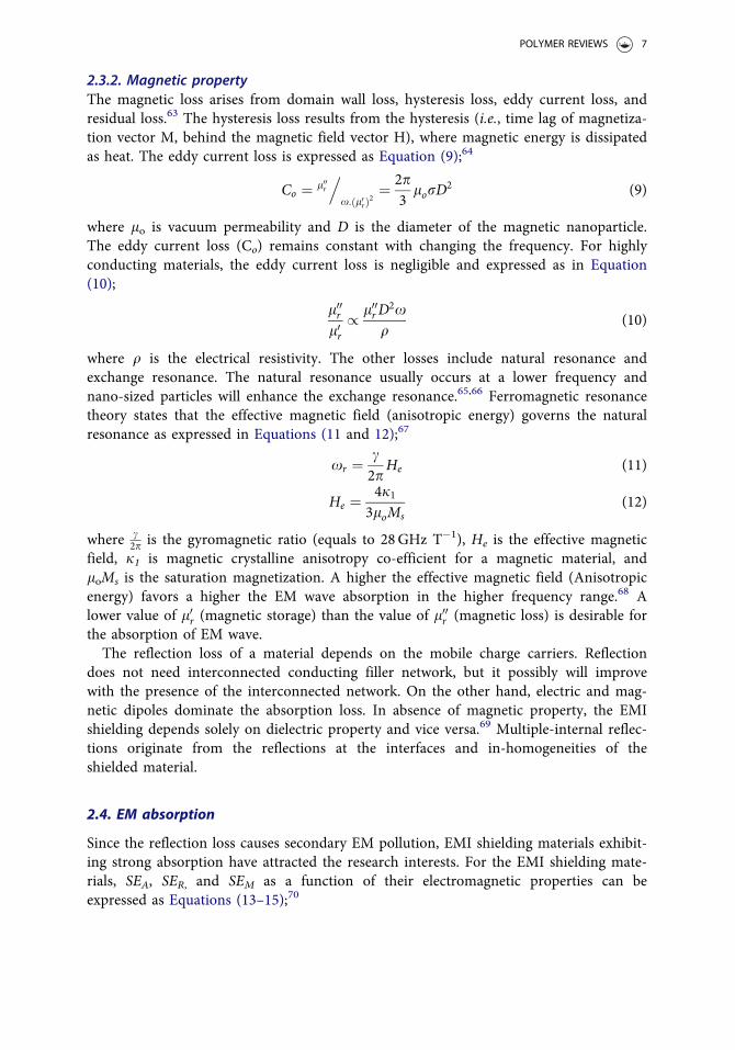
Figure 5 represents the attenuation constant in the X-band range for PVdF/TPU blends(50/50) containing different loadings of Fe-Ni alloy@MWCNT. It can be observed thatthe EM attenuation for polymer blends containing pristine MWCNT and pristine Fe-Nialloy is lower than other composites containing both Fe-Ni alloy@ MWCNT due totheir poor permeability and poor permittivity, respectively. The PVdF/TPU polymerblend containing Fe-Ni alloy@ MWCNT in the 3:1 ratio exhibited a higher a, attributedto the impedance matching and a balance between the dielectric and magnetic proper-ties. These results portrayed that the importance of energy conservation and impedancematching instead of materials’ superior property.73
For highly conducting materials, its electrical conductivity (r) is the only keyparameter for SE because of their high tande (greater than 1). On the other hand, forthe materials whose conductivity is weak (tande � 1), both electrical conductivity andpermittivity are important parameters for ICP and CPC.74 Therefore, optimizing the
8 D. JIANG ET AL.
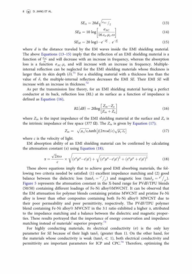
thickness and electromagnetic properties of EMI shielding materials is important toachieve effective EMI shielding and to govern the corresponding mechanism.75 Figure 6depicts the influence of shielding material’s thickness on its SET of thermoplastic poly-urethane (TPU) based CPC. It is apparent that the SET increases with an increase in thethickness of the shielding material. The higher EMI SE for the montmorillonite/DBSAdoped PPy (Mt-PPy.DBSA) is attributed to a better dispersion of Mt-PPy. DBSA thatprovides enhanced dipole and interface polarization and improved electricalconductivity.76
Figure 5. Attenuation constant of the PVdF/TPU (50/50) blends containing a different ratio ofFe-Ni@MWCNT in the X-band range. Reproduced with permission from ref.73 Copyright © Wiley-VCHVerlag GmbH & Co. KGaA, Weinheim.
Figure 6. EMI SE of TPU based CPC incorporated with HCl doped PPy (PPy.Cl); Montmorillonite/HCldoped PPy (Mt-PPy.Cl), DBSA doped PPy (PPy.DBSA) and Montmorillonite/DBSA doped PPy (Mt-PPy.DBSA) with respect to the shielding material thickness. �DBSA: Dodecyl benzene sulfonic acid.Reproduced with permission from ref.76 Copyright © 2018 John Wiley & Sons, Ltd.
POLYMER REVIEWS 9
2.5. Experimental determination of shielding effectiveness
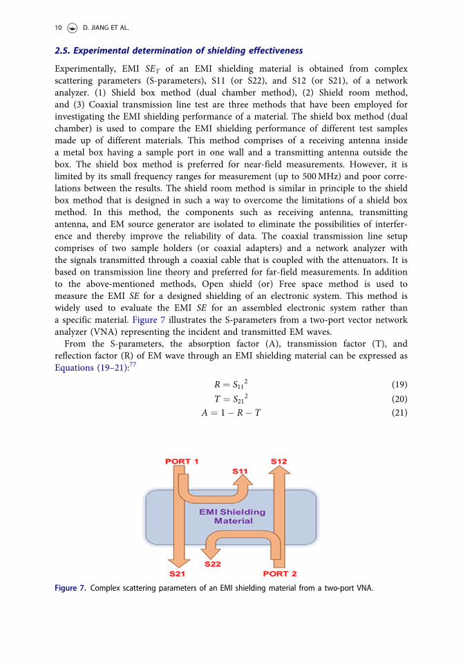
Experimentally, EMI SET of an EMI shielding material is obtained from complexscattering parameters (S-parameters), S11 (or S22), and S12 (or S21), of a networkanalyzer. (1) Shield box method (dual chamber method), (2) Shield room method,and (3) Coaxial transmission line test are three methods that have been employed forinvestigating the EMI shielding performance of a material. The shield box method (dualchamber) is used to compare the EMI shielding performance of different test samplesmade up of different materials. This method comprises of a receiving antenna insidea metal box having a sample port in one wall and a transmitting antenna outside thebox. The shield box method is preferred for near-field measurements. However, it islimited by its small frequency ranges for measurement (up to 500MHz) and poor corre-lations between the results. The shield room method is similar in principle to the shieldbox method that is designed in such a way to overcome the limitations of a shield boxmethod. In this method, the components such as receiving antenna, transmittingantenna, and EM source generator are isolated to eliminate the possibilities of interfer-ence and thereby improve the reliability of data. The coaxial transmission line setupcomprises of two sample holders (or coaxial adapters) and a network analyzer withthe signals transmitted through a coaxial cable that is coupled with the attenuators. It isbased on transmission line theory and preferred for far-field measurements. In additionto the above-mentioned methods, Open shield (or) Free space method is used tomeasure the EMI SE for a designed shielding of an electronic system. This method iswidely used to evaluate the EMI SE for an assembled electronic system rather thana specific material. Figure 7 illustrates the S-parameters from a two-port vector networkanalyzer (VNA) representing the incident and transmitted EM waves.From the S-parameters, the absorption factor (A), transmission factor (T), and
reflection factor (R) of EM wave through an EMI shielding material can be expressed asEquations (19–21):77
R ¼ S112 (19)
T ¼ S212 (20)
A ¼ 1� R� T (21)
Figure 7. Complex scattering parameters of an EMI shielding material from a two-port VNA.
10 D. JIANG ET AL.
The corresponding SEA, SER, and SET can be calculated from Equations (22–24):
SER ¼ �log10 1�Rð Þ (22)
SEA ¼ �log10T
1� R
� �(23)
SET ¼ SEA þ SER SEM is negligibleð Þ: (24)
A better understanding of the absorption by an EMI shielding material can beobtained by calculating its effective absorption (Aeff) percentage using Equation (25):78
Aeff ¼ 1�R�Tð Þ1� Rð Þ � 100 %ð Þ (25)
while, Aeff determines the power that is absorbed by the EMI shielding material.
3. Intrinsically conducting polymers (ICPs)
Delocalization of p-electrons in a conjugated structure of ICP such as polyacetylene(Pan), polyaniline (PANI), polypyrrole (PPy), etc. has drawn their attention for EMIapplications, as it provides a unique electronic property which can be tuned by doping/dedoping during their synthesis. However, extensive delocalization of p-electrons hin-ders their processability.79 Also, they suffer from swelling, contraction, cracking, or soft-ening that in turn affect their mechanical and electrical properties. These properties canbe improved by introducing a second phase materials such as metal nanoparticles, mag-netic materials, carbon nanostructures, metal oxides, etc.80 The second phase materialsimprove the dielectric and magnetic property and thermal stability of the ICP withoutdeteriorating their electrical conductivity, thereby enhancing the EMI SE or EM waveabsorption. The e0r of the ICP composites is greater than that of pristine ICP. This incre-ment is the result of enhanced interfacial polarization of large interfacial area andincongruity in the dielectric property between the ICP and second phase materials.
3.1. Parameter influencing the properties of ICP for EMI shielding
The EMI shielding ability of the ICP (both reflection and absorption) arises from themobile charges (polarons and bipolarons) and bound charges (dipoles) at their back-bone.81 The ability to control their electrical conductivity by governing their oxidationstate, doping, chemical structure, and morphology makes them an efficient candidatefor EMI shielding.82
The electrical conductivity for the ICP composites depends on the reaction conditionsduring polymerization. For example, Wan et al. demonstrated that the electrical con-ductivity of bacterial cellulose/graphene/PANI (BC/GN/PANI) nanocompositesdecreases from 0.82 to 0.74 S.cm�1 on increasing the reaction temperature from 0 to25 �C, whereas, increases from 8.5� 10�5 to �1 S.cm�1 on increasing the reaction timefrom 2 to 10 hr.83 The tendency of conducting polymers to agglomerate at a higherreaction temperature decreases their electrical conductivity. On contrary, an increasedelectrical conductivity at a longer reaction time is attributed to the increase in theamount of conducting polymers.84 Doping of surfactants onto conducting polymers
POLYMER REVIEWS 11
improves the electron mobility by increasing the polarons and bipolarons concentration.For example, Bhardwaj et al. reported that sodium lauryl sulfate (SLS) doping restrictsthe bias dependency for interchain hopping of charge carriers and thereby enhances theelectrical conductivity and EMI SE.81 The morphology, chemical composition, and elec-trical conductivity can be modified by doping acids, that in turn affect the EMI SE.85,86
Qiu et al. demonstrated that the phosphoric acid (H3PO4) yielded nanofiber-like struc-ture whereas hydrochloric acid (HCl), and L(-)-camphor sulfonic acid (CSA), yieldedholothurian-like structures for PANI.87 The CSA doped PANI exhibited highest elec-trical conductivity that results from the increased delocalization of electrons by theirhydroxyl group and morphological effect. He et al.88 demonstrated that the r of wood/PANI composites increased with increasing the concentration of phosphoric acid (PA).Here, the wood refers to the Wood veneers obtained from the tree, Entandrophragmacylindricum. However, the addition of PA beyond the optimum concentration of 0.6M,decreased their electrical conductivity. The wood/PANI composites with 0.6M PAexhibited the r of 9.53� 10�3 S cm�1 and EMI SE of �45–60 dB between 10 and1.5GHz.88 Tantawy et al. demonstrated that HCl doped PANI prepared by the solid-state reaction exhibited higher range of r and EMI SE than that are prepared by con-ventional solution method.89 Gahlout et al. demonstrated the effect of oxidant (FeCl3)and concentration of dopant on the r and EMI SE of PPy. Various dopants such assodium lauryl sulfate (SLS), sodium dodecylbenzene sulfonate (SDBS), and naphthalenedisulphonic acid (NDSA) were used. PPy prepared at pyrrole: oxidant: dopant ratio of1:2:1 with SLS as dopant exhibited the highest r of 42 S.cm�1. The EMI SE exhibited bythe same is �126 dB in the X-band range.90 Kaur et al. found that the increase in thesurfactant concentration (SLS) from 5 to 30mM, decreased the particle size from 53 to28 nm, increased the electrical conductivity from 3 to 22 S.cm�1 and increased the EMISE from 23 to 49 dB for PPy nanoparticles.91 The observation from these studiesrevealed that the chemical formulation also can influence the properties of conductingpolymers. Ebrahimi et al. compared r and EMI SE of Ag incorporated PPy-MWNCTscomposites prepared by UV-reduction and chemical reduction method. The compositesprepared by UV-reduction methods exhibited higher r and EMI SE due to higher con-tent (57%) and homogenous distribution of silver nanoparticles at the PPy-MWCNTinterfaces in comparison to that prepared by chemically reduced composites (40%).92
3.2. ICP based composites in EMI shielding
Metal nanoparticles such as copper, nickel, etc. were used as a second phase materialwith the ICP.93 20wt% of silver nanowires has been incorporated into PPy to achieve aflexible EMI shielding film. The conductivity of PPy/AgNWs film increased from 0.02 S/cm for pure PPy to 62.73 S/cm, and thus its SET increased to 22.38 dB.94 The higherSET is attributed to the electron scattering at the interfaces and surface plasmon reso-nances of the metal nanoparticles. However, metal nanoparticles suffer from heavy-weight and corrosion.Metal oxides are used as the second phase material in the ICP matrix for enhancing
their dielectric properties. A modified phase generated by the metal oxides at the inter-face restricts the movement of charge carriers in the ICP backbone. This accumulation
12 D. JIANG ET AL.
of charges will enhance the capacitance of ICP/metal oxide composites thereby increasesthe dielectric constant. Further, metal oxide fillers can overcome the drawbacks of metalfillers such as heavyweight and poor corrosion resistance, as they possess excellent cor-rosion resistance and thermal stability. For example, Faisal et al. reported PANI/Sb2O3
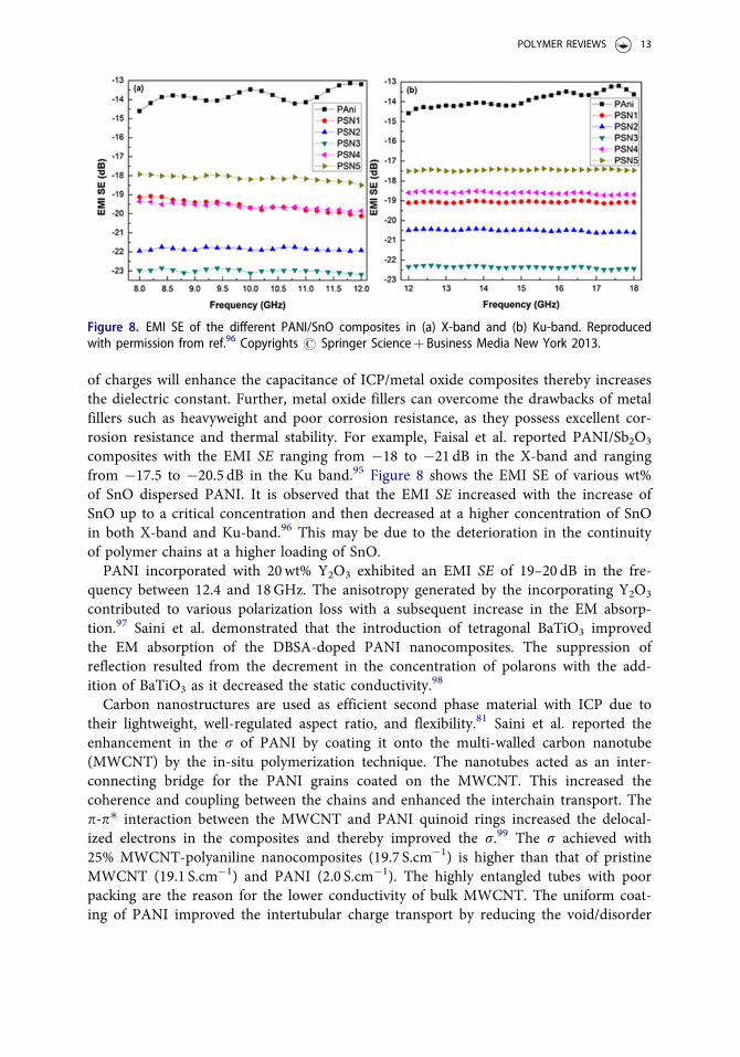
composites with the EMI SE ranging from �18 to �21 dB in the X-band and rangingfrom �17.5 to �20.5 dB in the Ku band.95 Figure 8 shows the EMI SE of various wt%of SnO dispersed PANI. It is observed that the EMI SE increased with the increase ofSnO up to a critical concentration and then decreased at a higher concentration of SnOin both X-band and Ku-band.96 This may be due to the deterioration in the continuityof polymer chains at a higher loading of SnO.PANI incorporated with 20wt% Y2O3 exhibited an EMI SE of 19–20 dB in the fre-
quency between 12.4 and 18GHz. The anisotropy generated by the incorporating Y2O3
contributed to various polarization loss with a subsequent increase in the EM absorp-tion.97 Saini et al. demonstrated that the introduction of tetragonal BaTiO3 improvedthe EM absorption of the DBSA-doped PANI nanocomposites. The suppression ofreflection resulted from the decrement in the concentration of polarons with the add-ition of BaTiO3 as it decreased the static conductivity.98
Carbon nanostructures are used as efficient second phase material with ICP due totheir lightweight, well-regulated aspect ratio, and flexibility.81 Saini et al. reported theenhancement in the r of PANI by coating it onto the multi-walled carbon nanotube(MWCNT) by the in-situ polymerization technique. The nanotubes acted as an inter-connecting bridge for the PANI grains coated on the MWCNT. This increased thecoherence and coupling between the chains and enhanced the interchain transport. Thep-p� interaction between the MWCNT and PANI quinoid rings increased the delocal-ized electrons in the composites and thereby improved the r.99 The r achieved with25% MWCNT-polyaniline nanocomposites (19.7 S.cm�1) is higher than that of pristineMWCNT (19.1 S.cm�1) and PANI (2.0 S.cm�1). The highly entangled tubes with poorpacking are the reason for the lower conductivity of bulk MWCNT. The uniform coat-ing of PANI improved the intertubular charge transport by reducing the void/disorder
Figure 8. EMI SE of the different PANI/SnO composites in (a) X-band and (b) Ku-band. Reproducedwith permission from ref.96 Copyrights # Springer Scienceþ Business Media New York 2013.
POLYMER REVIEWS 13
in the composites. The absorption dominated SET of �27.5 to �39.2 dB was achieved inthe frequency range of 12.4–18.0GHz.100
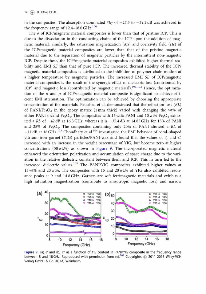
The r of ICP/magnetic material composites is lower than that of pristine ICP. This isdue to the dissociation in the conducting chains of the ICP upon the addition of mag-netic material. Similarly, the saturation magnetization (Ms) and coercivity field (Hc) ofthe ICP/magnetic material composites are lower than that of the pristine magneticmaterial due to the separation of magnetic particles by the intermittent non-magneticICP. Despite these, the ICP/magnetic material composites exhibited higher thermal sta-bility and EMI SE than that of pure ICP. The increased thermal stability of the ICP/magnetic material composites is attributed to the inhibition of polymer chain motion ata higher temperature by magnetic particles. The increased EMI SE of ICP/magneticmaterial composites is the result of the synergic effect of dielectric loss (contributed byICP) and magnetic loss (contributed by magnetic material).101,102 Hence, the optimiza-tion of the r and l of ICP/magnetic material composite is significant to achieve effi-cient EMI attenuation. The optimization can be achieved by choosing the appropriateconcentration of the materials. Belaabed et al. demonstrated that the reflection loss (RL)of PANI/Fe3O4 in the epoxy matrix (1mm thick) varied with changing the wt% ofeither PANI or/and Fe3O4. The composites with 15wt% PANI and 10wt% Fe3O4 exhib-ited a RL of �42 dB at 16.3GHz, whereas it is �37.4 dB at 14.85GHz for 15% of PANIand 25% of Fe3O4. The composites containing only 20% of PANI showed a RL of�11 dB at 18GHz.103 Choudhary et al.104 investigated the EMI behavior of coral–shapedyttrium–iron–garnet (YIG) particles/PANI-wax and found that the values of e0r and e00rincreased with an increase in the weight percentage of YIG, but become zero at higherconcentrations (50wt.%) as shown in Figure 9. The incorporated magnetic materialenhanced the orientation polarization and accumulation of space charge due to the vari-ation in the relative dielectric constant between them and ICP. This in turn led to theincreased dielectric values.105 The PANI/YIG composites exhibited higher values at15wt% and 20wt%. The composites with 15 and 20wt.% of YIG also exhibited reson-ance peaks at 9 and 14.8GHz. Garnets are soft ferrimagnetic materials and exhibits ahigh saturation magnetization (contribute to anisotropic magnetic loss) and narrow
Figure 9. (a) e’ and (b) e’’ as a function of YIS content in PANI/YIG composite in the frequency rangebetween 8 and 18GHz. Reproduced with permission from ref.104 Copyrights # 2011 2018 Wiley-VCHVerlag GmbH & Co. KGaA, Weinheim.
14 D. JIANG ET AL.
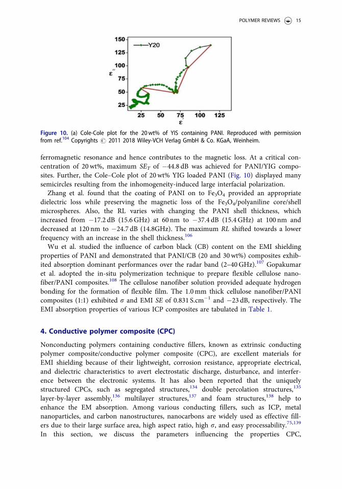
ferromagnetic resonance and hence contributes to the magnetic loss. At a critical con-centration of 20wt%, maximum SET of �44.8 dB was achieved for PANI/YIG compo-sites. Further, the Cole–Cole plot of 20wt% YIG loaded PANI (Fig. 10) displayed manysemicircles resulting from the inhomogeneity-induced large interfacial polarization.Zhang et al. found that the coating of PANI on to Fe3O4 provided an appropriate
dielectric loss while preserving the magnetic loss of the Fe3O4/polyaniline core/shellmicrospheres. Also, the RL varies with changing the PANI shell thickness, whichincreased from �17.2 dB (15.6GHz) at 60 nm to �37.4 dB (15.4GHz) at 100 nm anddecreased at 120 nm to �24.7 dB (14.8GHz). The maximum RL shifted towards a lowerfrequency with an increase in the shell thickness.106
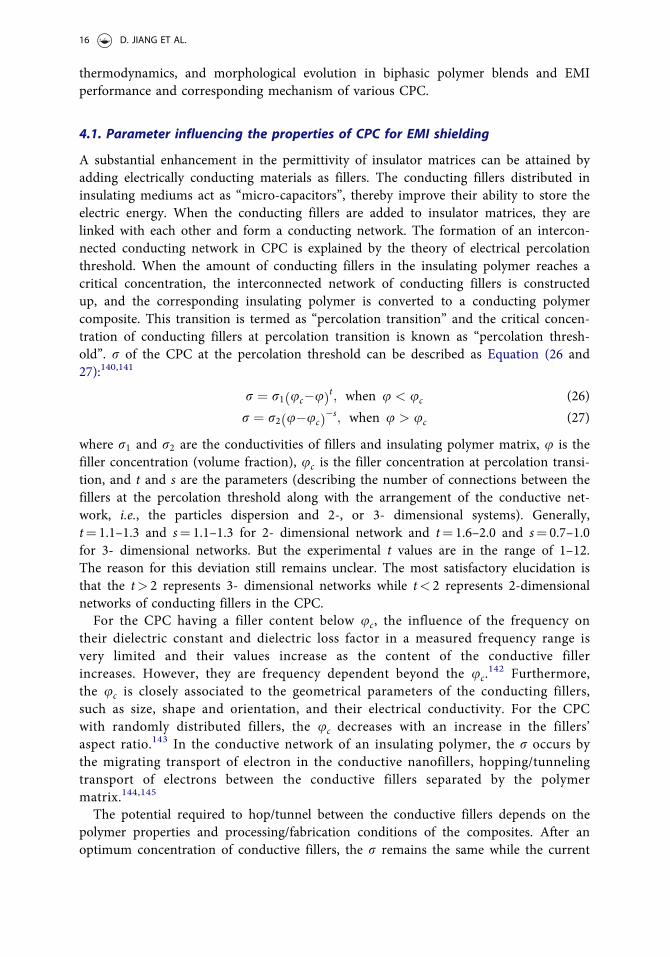
Wu et al. studied the influence of carbon black (CB) content on the EMI shieldingproperties of PANI and demonstrated that PANI/CB (20 and 30wt%) composites exhib-ited absorption dominant performances over the radar band (2–40GHz).107 Gopakumaret al. adopted the in-situ polymerization technique to prepare flexible cellulose nano-fiber/PANI composites.108 The cellulose nanofiber solution provided adequate hydrogenbonding for the formation of flexible film. The 1.0mm thick cellulose nanofiber/PANIcomposites (1:1) exhibited r and EMI SE of 0.831 S.cm�1 and �23 dB, respectively. TheEMI absorption properties of various ICP composites are tabulated in Table 1.
4. Conductive polymer composite (CPC)
Nonconducting polymers containing conductive fillers, known as extrinsic conductingpolymer composite/conductive polymer composite (CPC), are excellent materials forEMI shielding because of their lightweight, corrosion resistance, appropriate electrical,and dielectric characteristics to avert electrostatic discharge, disturbance, and interfer-ence between the electronic systems. It has also been reported that the uniquelystructured CPCs, such as segregated structures,134 double percolation structures,135
layer-by-layer assembly,136 multilayer structures,137 and foam structures,138 help toenhance the EM absorption. Among various conducting fillers, such as ICP, metalnanoparticles, and carbon nanostructures, nanocarbons are widely used as effective fill-ers due to their large surface area, high aspect ratio, high r, and easy processability.75,139
In this section, we discuss the parameters influencing the properties CPC,
Figure 10. (a) Cole-Cole plot for the 20wt% of YIS containing PANI. Reproduced with permissionfrom ref.104 Copyrights # 2011 2018 Wiley-VCH Verlag GmbH & Co. KGaA, Weinheim.
POLYMER REVIEWS 15
thermodynamics, and morphological evolution in biphasic polymer blends and EMIperformance and corresponding mechanism of various CPC.
4.1. Parameter influencing the properties of CPC for EMI shielding
A substantial enhancement in the permittivity of insulator matrices can be attained byadding electrically conducting materials as fillers. The conducting fillers distributed ininsulating mediums act as “micro-capacitors”, thereby improve their ability to store theelectric energy. When the conducting fillers are added to insulator matrices, they arelinked with each other and form a conducting network. The formation of an intercon-nected conducting network in CPC is explained by the theory of electrical percolationthreshold. When the amount of conducting fillers in the insulating polymer reaches acritical concentration, the interconnected network of conducting fillers is constructedup, and the corresponding insulating polymer is converted to a conducting polymercomposite. This transition is termed as “percolation transition” and the critical concen-tration of conducting fillers at percolation transition is known as “percolation thresh-old”. r of the CPC at the percolation threshold can be described as Equation (26 and27):140,141
r ¼ r1 uc�uð Þt; when u < uc (26)
r ¼ r2 u�ucð Þ�s; when u > uc (27)
where r1 and r2 are the conductivities of fillers and insulating polymer matrix, u is thefiller concentration (volume fraction), uc is the filler concentration at percolation transi-tion, and t and s are the parameters (describing the number of connections between thefillers at the percolation threshold along with the arrangement of the conductive net-work, i.e., the particles dispersion and 2-, or 3- dimensional systems). Generally,t¼ 1.1–1.3 and s¼ 1.1–1.3 for 2- dimensional network and t¼ 1.6–2.0 and s¼ 0.7–1.0for 3- dimensional networks. But the experimental t values are in the range of 1–12.The reason for this deviation still remains unclear. The most satisfactory elucidation isthat the t> 2 represents 3- dimensional networks while t< 2 represents 2-dimensionalnetworks of conducting fillers in the CPC.For the CPC having a filler content below uc, the influence of the frequency on
their dielectric constant and dielectric loss factor in a measured frequency range isvery limited and their values increase as the content of the conductive fillerincreases. However, they are frequency dependent beyond the uc.
142 Furthermore,the uc is closely associated to the geometrical parameters of the conducting fillers,such as size, shape and orientation, and their electrical conductivity. For the CPCwith randomly distributed fillers, the uc decreases with an increase in the fillers’aspect ratio.143 In the conductive network of an insulating polymer, the r occurs bythe migrating transport of electron in the conductive nanofillers, hopping/tunnelingtransport of electrons between the conductive fillers separated by the polymermatrix.144,145
The potential required to hop/tunnel between the conductive fillers depends on thepolymer properties and processing/fabrication conditions of the composites. After anoptimum concentration of conductive fillers, the r remains the same while the current
16 D. JIANG ET AL.
carrying capability of the polymer composites increases. The dependency of the r onthe distance between the two conductive fillers in a polymer matrix is given byEquation (28):146
r � x exp � xa
� �(28)
where x is the gap between the two conducting fillers in a polymer matrix and a is thecharacteristic tunneling distance. Figure 11 shows the change in r and the EMI SE withrespect to the filler loading for Printex black (P-CB) loaded polymer blend of two
Table 1. EMI Absorption characteristics of ICP and their composites.
MaterialsAbsorber
loading (wt.%)MaximumRL (dB)
Frequency atMaximumRL (GHz)
Bandwidthrange (GHz) RL< �10 dB
d @ RLMaxima (mm) Ref.
Epoxy-PPy/Fe3O4-ZnO — �32.53 dB 9.96 8.8–12.4(<–10dB) &9.7–10.9(<�20dB)
2.0 109
Fe3O4/GNPs-NH-PANI — �40.31 — 7.85–17.47 2.6 110
GN-PANI-Fe3O4 in paraffin 50% �43.9 11.4 5.4–16.4 2.5 111
Ni/PANI/rGO — �51.3 4.9 3.3–6.4 3.5 112
PANI-rGO-Co3O4 in paraffin 50% �32.6 6.3 3.4–11.8& 12.9–18
3.0 113
PPy-rGO-Co3O4 in paraffin 50% �33.5 15.8 6.6–18.0 2.5 114
PPy-BaFe12O19/Ni0.8Zn0.2Fe2O4 in paraffin
70% �25.5 9.8 7.8–11.6 3.0 115
FeNi3@SiO2@rGO–PANIin paraffin
25% �40.18 14.0 10.08–10.8& 12.08–18.0
2.4 116
FeCo@SnO2@GN@PANIin paraffin
30% �39.8 6.4 4.6–7.7 3.0 117
RGO/CoFe2O4/ MWCNT — �46.8 11.6 4.9–18 1.6 118
GN@Fe3O4@C@PANIin paraffin
25% �44.2 11.4 9.7–15.5 3.0 119
N-GN@PANI nanorodin paraffin
25% �38.8 7.3 6.5–8.8 3.0 120
GN@Fe3O4@PANI@TiO2
nanosheets in paraffin50% �41.8 14.4 7.0–8.5
& 10.2–16.21.4 121
FeCo@GNe@PPy in paraffin 30% �40.7 5.7 3.1–6& 12.8–15.6
2.5 122
CI/RGO/PVP in paraffin 50% �27.59 6.88 4.2–18 2.5 123
GN/PEDOT/CoFe2O4
in paraffin50% �43.2 9.4 8.2–11.3 2.4 124
PPy/rGO aerogel in paraffin 15% �54.4 12.76 10.20–16.96 3.0 125
Fe3O4/PPy/carbon in epoxy 20% �25.9 10.2 8.0–12.5 3.0 126
RGO/p-Fe3O4/PANI in paraffin 70% �29.51 14.69 — 1.0 127
Cubic NiFe2O4/GN-PANI — �50.5 12.5 11.0–16.3 2.5 128
GN@CoFe2O4@polyanilinein paraffin
50% �47.7 14.9 12.3–18(<�10dB)
&14–16(<�20dB)
1.6 129
PANI/Nanoflower-like CuSin paraffin
20% �45.2 2.78 0.3–3 3.0 130
PANI/RGO in paraffin 50% �41.4 13.8 11.7–15.9(<�10dB) &12.8–14.3(<�20dB)
2.0 131
PANI in paraffin 30% �40.5 5.8 3.2–18 5.0 132
PANI/Ba(CoTi)0.25Fe11.75O19
in paraffin50% �45.2 11.2 �10–13.8 2.5 133
POLYMER REVIEWS 17
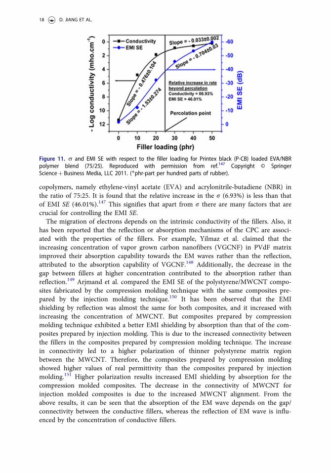
copolymers, namely ethylene-vinyl acetate (EVA) and acrylonitrile-butadiene (NBR) inthe ratio of 75:25. It is found that the relative increase in the r (6.93%) is less than thatof EMI SE (46.01%).147 This signifies that apart from r there are many factors that arecrucial for controlling the EMI SE.The migration of electrons depends on the intrinsic conductivity of the fillers. Also, it
has been reported that the reflection or absorption mechanisms of the CPC are associ-ated with the properties of the fillers. For example, Yilmaz et al. claimed that theincreasing concentration of vapor grown carbon nanofibers (VGCNF) in PVdF matriximproved their absorption capability towards the EM waves rather than the reflection,attributed to the absorption capability of VGCNF.148 Additionally, the decrease in thegap between fillers at higher concentration contributed to the absorption rather thanreflection.149 Arjmand et al. compared the EMI SE of the polystyrene/MWCNT compo-sites fabricated by the compression molding technique with the same composites pre-pared by the injection molding technique.150 It has been observed that the EMIshielding by reflection was almost the same for both composites, and it increased withincreasing the concentration of MWCNT. But composites prepared by compressionmolding technique exhibited a better EMI shielding by absorption than that of the com-posites prepared by injection molding. This is due to the increased connectivity betweenthe fillers in the composites prepared by compression molding technique. The increasein connectivity led to a higher polarization of thinner polystyrene matrix regionbetween the MWCNT. Therefore, the composites prepared by compression moldingshowed higher values of real permittivity than the composites prepared by injectionmolding.151 Higher polarization results increased EMI shielding by absorption for thecompression molded composites. The decrease in the connectivity of MWCNT forinjection molded composites is due to the increased MWCNT alignment. From theabove results, it can be seen that the absorption of the EM wave depends on the gap/connectivity between the conductive fillers, whereas the reflection of EM wave is influ-enced by the concentration of conductive fillers.
Figure 11. r and EMI SE with respect to the filler loading for Printex black (P-CB) loaded EVA/NBRpolymer blend (75/25). Reproduced with permission from ref.147 Copyright © SpringerScienceþ Business Media, LLC 2011. (�phr-part per hundred parts of rubber).
18 D. JIANG ET AL.
However, the addition of conducting fillers reduces the mechanical performance ofCPC, because the conductive network formed by the conducting fillers greatly con-strains the motion of the polymers’ molecular chain, resulting in the inferior toughnessand ductility of the CPC. Some works are focused on using the hybrid fillers to enhancethe mechanical performance of CPC as the incorporation of hybrid fillers with betterconductivity decreases the uc. The shape, size, and dispersibility of the conductive fillersalso play a vital role in defining the uc. For example, Joseph et al. demonstrated thatthe 2wt% carbon nanofiber (CNF) filled silicone rubber (SR) exhibited an EMI SEhigher than the 2wt% of MWCNT filled SR in the frequency range of 2.0–18.4GHz.This is due to that in the measured frequency region, the wavelength is nearly equal tothe length of CNF but higher than the length of MWCNT. The SR filled with CNFwafer exhibited a higher EMI SE than SR filled with 2wt% of CNF due to the improvedelectrical contact. Also, when the thickness of the CNF wafer was increased from 0.73to 0.75mm, an increase in EMI SE from 35.08 to 38.95 dB was observed.152 For thecomposites containing the fillers whose length is less than the wavelength of EM wave,the EMI SE depends more on conductivity than the imaginary permittivity due to thelack of interaction between them. Satisfactory dispersion of the conducting filler in thepolymer is associated with the appropriate selection of process parameters and thefiller-polymer compatibility. The efficient filler-polymer interaction prevents the aggre-gation of conducting fillers, which in turn provides superior EMI SE. The filler-polymerinteraction can be investigated by a parameter, Bound Rubber content (BRC), whichcan be calculated using the Equation (29):153,154
BRC ¼ 100� Wfg�Wt mf = mf þmfð Þ�
Wt mf = mf þmrð Þ� (29)
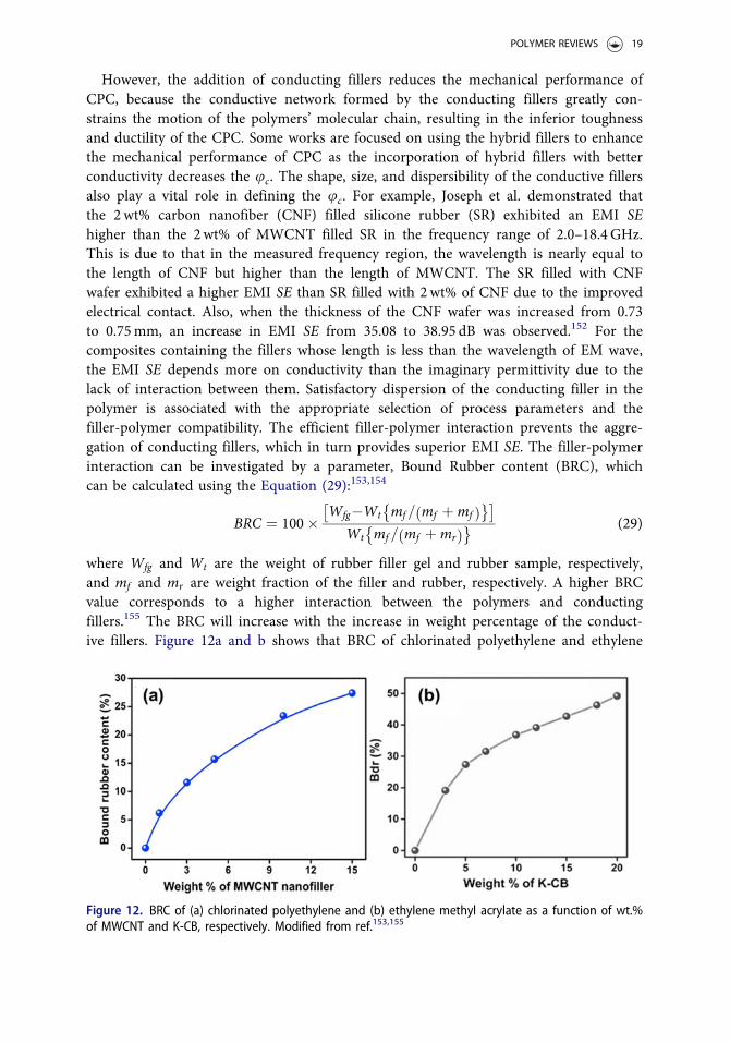
where Wfg and Wt are the weight of rubber filler gel and rubber sample, respectively,and mf and mr are weight fraction of the filler and rubber, respectively. A higher BRCvalue corresponds to a higher interaction between the polymers and conductingfillers.155 The BRC will increase with the increase in weight percentage of the conduct-ive fillers. Figure 12a and b shows that BRC of chlorinated polyethylene and ethylene
Figure 12. BRC of (a) chlorinated polyethylene and (b) ethylene methyl acrylate as a function of wt.%of MWCNT and K-CB, respectively. Modified from ref.153,155
POLYMER REVIEWS 19
methyl acrylate increases with an increase in the weight percentage of the correspondingfillers (MWCNT and Ketjen carbon black (K-CB), respectively). More interaction willincrease the permittivity of the CPC due to the collected charges at their interface,attributed to the alteration in relaxation time of polymer and fillers.156
Altering the chemical vicinity and the functionalization of the carbonaceous fillersimproves their dispersion and interaction with the polymer matrices which in turninfluence the uc, impedance matching as well as EMI shielding performance.157–161 Forexample, Bose et al. constructed a ternary continuous structure in which the pristineMWCNTs (p-MWCNTs) were confined in the PVDF phase whereas, PMMA wrappedMWCNTs (PMMA-MWCNTs) were confined at the interface of PVDF/ABS (50/50) co-continuous blends. An EMI SE of �24 dB (at 18GHz frequency) was obtained for 50/50blends with 3wt% MWCNTs.162 The same group also reported a high RL of �61 dB at12.7GHz for PVdF/PC blends containing PMMA-MWCNT. Higher dielectric relaxationlosses due to the accumulation of virtual charges in the interfacial region of heteroge-neous dielectrics increase the complex permittivity and result in higher reflectionlosses.163 Wu et al. functionalized the graphene foam (GF) with DBSA to improve itswettability and bond formation with PEDOT: PSS.164 The prepared PEDOT: PSS/GFexhibited negative permittivity ascribed to the delocalization of polarized charges at theinterfaces.165 The optimized PEDOT: PSS/GF composites exhibited the largest EMI SEsof 91.9 dB, attributed to the enhanced interaction between the constituents by the add-ition of DBSA. Liang et al. revealed that the functionalized graphene exhibited lowuc of 0.52 vol.% in the epoxy matrix and achieved an EMI SE of �21 dB at 8.8 vol.% inX-band.166 Zhang et al. studied the effect of carbon to oxygen (C/O) ratio on thedispersion of graphene in PMMA matrix and their corresponding EMI SE.167 Thegraphene with highest C/O ratio (13.2) displayed a better dispersion in PMMA thanthe graphene with the lowest ratio, with an EMI SE of �30 dB at 4.2 vol%. Li et al.prepared thermally reduced functionalized graphene incorporated polystyrene foamand achieved r and EMI SE of 1.1� 10�2 S.m�1 and �18 dB, respectively at10 wt%.168 Hsiao et al. achieved homogenous dispersion of graphene in a water-borne polyurethane (WPU) matrix by covalently modification using aminoethylmethacrylate. At 5 vol.% loading, the prepared CPC exhibited an r of 43.64 S.m�1
and EMI SE of 38 dB in X-band.169 They also demonstrated that the noncovalentfunctionalization of graphene sheets (GNS) with stearyl trimethyl ammonium chlor-ide improved their interaction with sulfonated WPU and decreased the uc. At5 vol.% of GNS, the CPC achieved an EMI SE of 32 dB.170 Further, the same researchgroup also composited positively charged cationic surfactant (didodecyl dimethylammonium bromide, DDAB) adsorbed graphene oxide and negatively charged sulfo-nated functional group containing electrospun WPU using electrostatic attractionbetween them by layer-by-layer assembly method, which exhibited EMI SE of�34 dB in the X-band for a sample with a thickness of 1.0 mm.171 Poothanari et al.used polar copolymer, polypropylene-grafted maleic anhydride (PP-g-MA), as com-patibilizer for polycarbonate (PC)/polypropylene (PP) polymer blend.172 The add-ition of PP-g-MA provided co-continuous morphology for PC/PP blend due to thereduced interfacial tension and diffused interface, which is unaffected by the inclu-sion of MWCNT. Also, it improved the dispersion of MWCNT. The compatibilized
20 D. JIANG ET AL.
PC/PP blend of 2mm thickness displayed an EMI SE of 54.78 dB at 3 GHz for10 wt% MWCNT loading. Tian et al. described that the nitrogen-doped reduced gra-phene oxide (N-RGO) obtained using diethylenetriamine (DETA) exhibited uniformdispersion in WPU matrix with r of 0.08 S.cm�1 and EMI SE of 28.3 dB at 9 GHz at12 wt% N-RGO content.173 However, the chemical modifications depreciate theintrinsic properties of the CPC’s constituents.174
Distribution of conducting fillers in the polymer matrix is influenced by fillerloading and filler-polymer interaction. There will be no specific interaction betweenthe filler and polymer at lower concentrations, whereas higher concentrations willgreatly change the distribution, polarity matching, polymer-filler interactions, andresulting in conductive network structures. But the aggregation of fillers due to theVander Waals’ interaction at the higher loading will negatively affect the mechanicaland thermal properties, processing and cost.175,176 Interestingly, the uc can bereduced by selective/preferential localization of conducting fillers in the polymer sys-tem, which is based on classical thermodynamics. The preferential localization of theconductive fillers increases their concentration at the local level and thereby gener-ates effective conductive networks.177 The segregated structure and double percola-tion structure are two main strategies to achieve selective localization, therebydepress the concentration of conductive fillers. Yan et al. achieved EMI SE rangingbetween 28.3 and 32.4 dB for polyethylene/graphene composites with the segregatedstructure at an ultralow filler content of 0.660 vol.%.178 Multi-facet segregated struc-tured RGO/polystyrene composites presented an admirable EMI SE of 45.1 dB thantheir conventional structures at 2.5 mm sample thickness and 3.47 vol.% offiller loading.179 The multi-facet segregated structure provides more interfacesthat enhance the EM attenuation. In segregated structure, the conducting fillers arefound at the polymer interfaces and form compact conductive structure, whereas,in double percolation structures, the conductive fillers are added to one continuouscomponent of two immiscible polymer blend to form complicated conductive struc-tures.180,181 In spite of the advantages, the segregated and double threshold CPCssuffer from following demerits: (a) In segregated CPC, the conductive layers formedby the conductive fillers hinder the molecular diffusion between the polymer matrixgranules, resulting in an extremely weak adhesive interaction, (b) In double thresh-old structures, the immiscible interface between the polymer blends leads to poorinterfacial interactions in CPC with a double-percolated structure. It is, therefore,necessary to eliminate the structural defects at the interfaces, which can be achievedby varying process/fabrication conditions. Wu et al. demonstrated that segregatedCNT/PP prepared at the elevated temperature and pressure of 180 �C and 100MPa,respectively using solid phase molding suppressed the interfacial defects andimproved the connectivity of CNT than that prepared by melt mixing.182 Thesegregated CNT/PP composites prepared by solid phase molding exhibited a SETof 17.1 dB at 0.3 wt% CNT, whereas CNT/PP prepared by melt mixing exhibiteda similar SET at 5 wt% CNT/PP composites with segregated structures. Comparedto the single-phase CPCs, two-phase CPCs has a lower uc and higher r alongwith higher EMI SE. The blend of two polymers having different polarity can forma well-defined interface where the fillers were expected to accumulate easily.183
POLYMER REVIEWS 21

4.1.1. Conditions for miscibility of two polymersThe condition for miscibility of the two polymers can be inferred from the Gibbsenergy of mixing DGmð Þ by Equation (30):
DGm ¼ DHm � TDSm (30)
where DHm and DSm are enthalpy and entropy of mixing, respectively. For miscibilityof the polymer blend, the following conditions must be satisfied: DGm < 0 and;ið ÞT;P > 0 where ;i is the amount (volume fraction) of the component i inthe mixture.In the equilibrium state, the distribution and position of fillers in CPC are controlled
by their interfacial energy. The thermodynamic tendency of the conducting fillers at thepolymer interface was reported by Sumita et al. as Equation (31):180
x12 ¼cFiller�Polymer1
�cFiller�Polymer2
cPolymer(31)
where c in the numerator indicates different interfacial tension between constituent fill-ers and polymers, and the denominator is the interfacial tension between the constitu-ents. When x12 > 1, filler would prefer polymer 2, when x12 < �1, the filler wouldprefer polymer 1, when �1 < x12 < 1, the filler is expected to confine at the inter-face.184–186 Interfacial tension between the components is given by Wu’s Equation asfollows:187
cAB ¼ cA þ cB � 4cdA:c
dB
cdA þ cdBþ cpA:c
pB
cpA þ cpB
" #(32)
where c, cd and cp are total surface tension, the dispersive and polar components of thesurface tension, respectively.Biswas et al. investigated the influence of conducting filler localization on the EMI SE
of the PC and polyvinylidene fluoride (PVDF) (50/50) blends.188 The localization of twodifferent fillers separately in two polymer phases enhanced the SET comparing to that ofcomposites containing two different fillers in the same polymer or in both the phases.This enhancement in the SET accounts for SEA while SER remains for all the samplesremain the same. Figure 13 demonstrates the above-explained conception. The polymerblend composites that contain 3wt% MWCNT in PVdF phase and BaTiO3 (BT) in PCphase (Fig. 13a) and 3wt% MWCNT in PVdF phase and NiFe2O4 (NF) in PC phase(Fig. 13b) exhibited a maximum SET than the composites that are containing BT/NF inPVdF phase and BT/NF in both PVdF phase or PC. This is attributed to the synergeticeffect arising from both phases containing nanosized fillers. Figure 13c and d displaysthat the percentage of absorption follows the same trend as SET.Further, the conducting fillers can easily form a closely packed interconnect conduct-
ive network in a polymer with amorphous phase compared with their semi-crystallinecounterparts.147 Figure 14 shows the morphological evolution and preferential localiza-tion of the biphasic polymers with respect to their mass ratio. It can be observed thatthe co-continuous phases exist and double percolation structures are formed for thepolymer blends with a mass ratio close to 1 (Fig. 14b–d). For higher mass ratio (Fig.14a and e), both the polymers are existing as droplets. More details on the
22 D. JIANG ET AL.
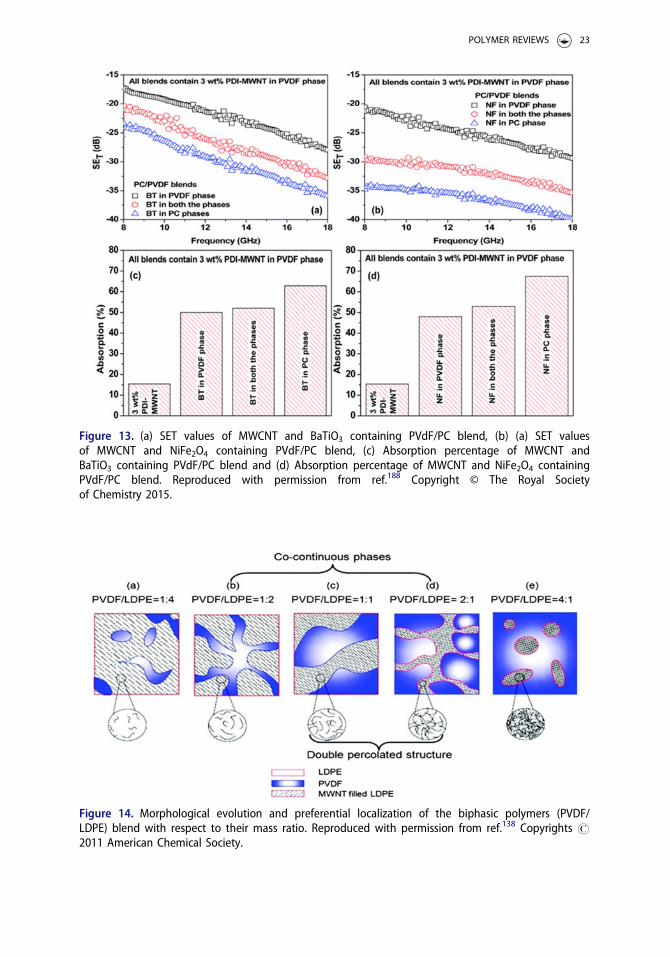
Figure 13. (a) SET values of MWCNT and BaTiO3 containing PVdF/PC blend, (b) (a) SET valuesof MWCNT and NiFe2O4 containing PVdF/PC blend, (c) Absorption percentage of MWCNT andBaTiO3 containing PVdF/PC blend and (d) Absorption percentage of MWCNT and NiFe2O4 containingPVdF/PC blend. Reproduced with permission from ref.188 Copyright © The Royal Societyof Chemistry 2015.
Figure 14. Morphological evolution and preferential localization of the biphasic polymers (PVDF/LDPE) blend with respect to their mass ratio. Reproduced with permission from ref.138 Copyrights #2011 American Chemical Society.
POLYMER REVIEWS 23
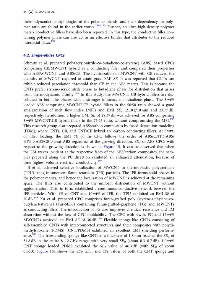
thermodynamics, morphologies of the polymer blends, and their dependency on poly-mer ratio are found in the earlier works.189–193 Further, an ultra-high-density polymermatrix conductive fillers have also been reported. In this type, the conductive filler con-taining polymer phase can also act as an effective binder that attributes to the reducedinterfacial flaws.194
4.2. Single-phase CPCs
Schmitz et al. prepared poly(acrylonitrile-co-butadiene-co-styrene) (ABS) based CPCscomprising CB/MWCNT hybrid as a conducting filler and compared their propertieswith ABS/MWCNT and ABS/CB. The hybridization of MWCNT with CB reduced thequantity of MWCNT required to attain good EMI SE. It was reported that CNTs canexhibit reduced percolation threshold than CB in the ABS matrix. This is because theCNTs prefer styrene-acrylonitrile phase to butadiene phase for distribution that arisesfrom thermodynamic affinity.195 In this study, the MWCNT: CB hybrid fillers are dis-tributed in both the phases with a stronger influence on butadiene phase. The 3wt%loaded ABS comprising MWCNT.CB hybrid fillers in the 50:50 ratio showed a goodamalgamation of melt flow index (MFI) and EMI SE, 12.10 g/10min and 23.77 dB,respectively. In addition, a higher EMI SE of 29.37 dB was achieved for ABS comprising3wt% MWCNT.CB hybrid fillers in the 75:25 ratio, without compromising the MFI.196
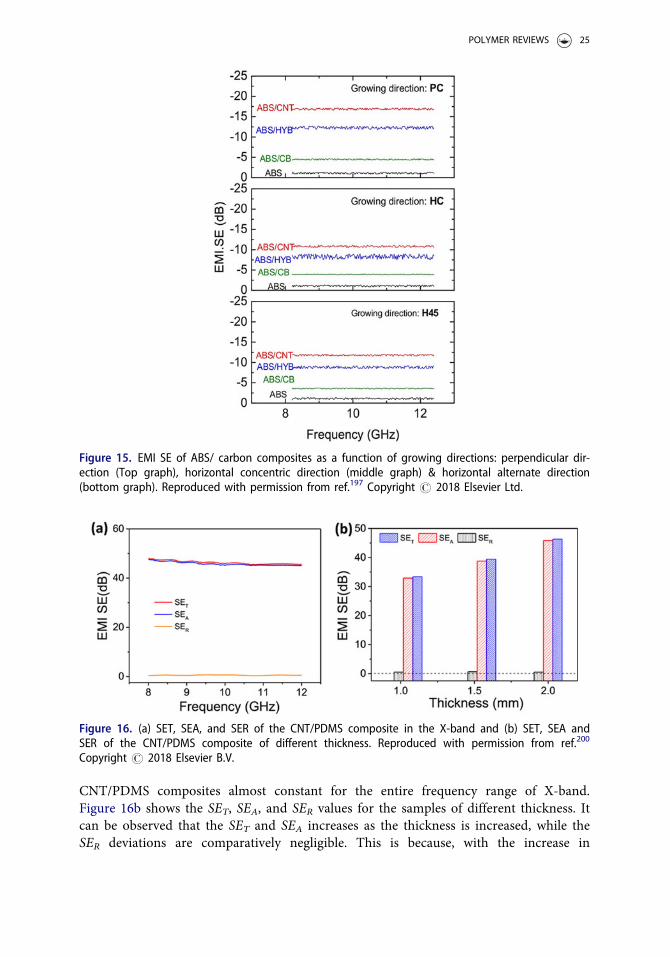
This research group also prepared ABS/carbon composites by fused deposition modeling(FDM), where CNTs, CB, and CNT/CB hybrid are carbon conducting fillers. At 3wt%of filler loading, the EMI SE of the CPC follows the order of ABS/CNT>ABS/HYB>ABS/CB> neat ABS regardless of the growing direction. SET of ABS CPCs withrespect to the growing direction is shown in Figure 15. It can be observed that whenthe EM waves incident at the respective faces of the ABS/carbon composites, the sam-ples prepared along the PC direction exhibited an enhanced attenuation, because oftheir highest volume electrical conductivity.197
Ji et al. achieved selective localization of MWCNT in thermoplastic polyurethane(TPU) using intumescent flame retardant (IFR) particles. The IFR forms solid phases inthe polymer matrix, and hence the localization of MWCNT is achieved at the remainingspace. The IFRs also contributed to the uniform distribution of MWCNT withoutagglomeration. This, in turn, established a continuous conductive network between theIFR particles. With 1% of CNT and 10wt% of IFR, the TPU exhibited an EMI SE of20 dB.198 Xu et al. prepared CPC comprises furan-grafted poly (styrene-(ethylene-co-butylene)-styrene) (Fur-SEBS) containing furan-grafted-graphene (FG) and MWCNTsas conducting fillers. The introduction of FG also improves chemical resistance and EMabsorption without the loss of CPC moldability. The CPC with 4wt% FG and 12wt%MWCNTs achieved an EMI SE of 36 dB.199 Flexible sponge-like CNTs consisting ofself-assembled CNTs with interconnected structures and their composites with polydi-methylsiloxane (PDMS) (CNT/PDMS) exhibited an excellent EMI shielding perform-ance.200 The freestanding sponge-like CNTs at a thickness of 1.8 mm reached the SET of54.8 dB in the entire 8–12 GHz range, with very small SER (about 0.3–0.7 dB). 1.0 wt%CNT sponge loaded PDMS exhibited the SET value of 46.3 dB (with SER of about0.5dB). Figure 16a shows the SET, SEA, and SER values of both the CNT sponge and
24 D. JIANG ET AL.
CNT/PDMS composites almost constant for the entire frequency range of X-band.Figure 16b shows the SET, SEA, and SER values for the samples of different thickness. Itcan be observed that the SET and SEA increases as the thickness is increased, while theSER deviations are comparatively negligible. This is because, with the increase in
Figure 15. EMI SE of ABS/ carbon composites as a function of growing directions: perpendicular dir-ection (Top graph), horizontal concentric direction (middle graph) & horizontal alternate direction(bottom graph). Reproduced with permission from ref.197 Copyright # 2018 Elsevier Ltd.
Figure 16. (a) SET, SEA, and SER of the CNT/PDMS composite in the X-band and (b) SET, SEA andSER of the CNT/PDMS composite of different thickness. Reproduced with permission from ref.200
Copyright # 2018 Elsevier B.V.
POLYMER REVIEWS 25
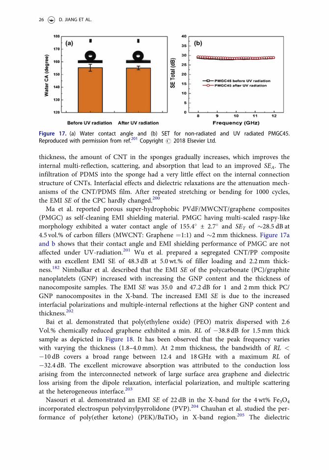
thickness, the amount of CNT in the sponges gradually increases, which improves theinternal multi-reflection, scattering, and absorption that lead to an improved SEA. Theinfiltration of PDMS into the sponge had a very little effect on the internal connectionstructure of CNTs. Interfacial effects and dielectric relaxations are the attenuation mech-anisms of the CNT/PDMS film. After repeated stretching or bending for 1000 cycles,the EMI SE of the CPC hardly changed.200
Ma et al. reported porous super-hydrophobic PVdF/MWCNT/graphene composites(PMGC) as self-cleaning EMI shielding material. PMGC having multi-scaled raspy-likemorphology exhibited a water contact angle of 155.4� ± 2.7� and SET of �28.5 dB at4.5 vol.% of carbon fillers (MWCNT: Graphene ¼1:1) and �2 mm thickness. Figure 17aand b shows that their contact angle and EMI shielding performance of PMGC are notaffected under UV-radiation.201 Wu et al. prepared a segregated CNT/PP compositewith an excellent EMI SE of 48.3 dB at 5.0 wt.% of filler loading and 2.2mm thick-ness.182 Nimbalkar et al. described that the EMI SE of the polycarbonate (PC)/graphitenanoplatelets (GNP) increased with increasing the GNP content and the thickness ofnanocomposite samples. The EMI SE was 35.0 and 47.2 dB for 1 and 2 mm thick PC/GNP nanocomposites in the X-band. The increased EMI SE is due to the increasedinterfacial polarizations and multiple-internal reflections at the higher GNP content andthickness.202
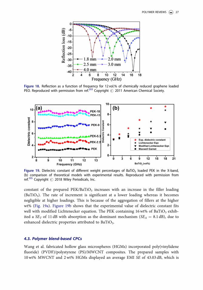
Bai et al. demonstrated that poly(ethylene oxide) (PEO) matrix dispersed with 2.6Vol.% chemically reduced graphene exhibited a min. RL of �38.8 dB for 1.5mm thicksample as depicted in Figure 18. It has been observed that the peak frequency varieswith varying the thickness (1.8–4.0mm). At 2mm thickness, the bandwidth of RL <
�10 dB covers a broad range between 12.4 and 18GHz with a maximum RL of�32.4 dB. The excellent microwave absorption was attributed to the conduction lossarising from the interconnected network of large surface area graphene and dielectricloss arising from the dipole relaxation, interfacial polarization, and multiple scatteringat the heterogeneous interface.203
Nasouri et al. demonstrated an EMI SE of 22 dB in the X-band for the 4wt% Fe3O4
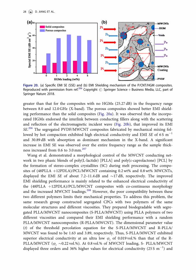
incorporated electrospun polyvinylpyrrolidone (PVP).204 Chauhan et al. studied the per-formance of poly(ether ketone) (PEK)/BaTiO3 in X-band region.205 The dielectric
Figure 17. (a) Water contact angle and (b) SET for non-radiated and UV radiated PMGC45.Reproduced with permission from ref.201 Copyright # 2018 Elsevier Ltd.
26 D. JIANG ET AL.
constant of the prepared PEK/BaTiO3 increases with an increase in the filler loading(BaTiO3). The rate of increment is significant at a lower loading whereas it becomesnegligible at higher loadings. This is because of the aggregation of fillers at the higherwt% (Fig. 19a). Figure 19b shows that the experimental value of dielectric constant fitswell with modified Lichtenecker equation. The PEK containing 16wt% of BaTiO3 exhib-ited a SET of 11 dB with absorption as the dominant mechanism (SEA ¼ 8.1 dB), due toenhanced dielectric properties attributed to BaTiO3.
4.3. Polymer blend-based CPCs
Wang et al. fabricated hollow glass microspheres (HGMs) incorporated poly(vinylidenefluoride) (PVDF)/polystyrene (PS)/MWCNT composites. The prepared samples with10wt% MWCNT and 2wt% HGMs displayed an average EMI SE of 43.03 dB, which is
Figure 18. Reflection as a function of frequency for 12 vol.% of chemically reduced graphene loadedPEO. Reproduced with permission from ref.203 Copyright # 2011 American Chemical Society.
Figure 19. Dielectric constant of different weight percentages of BaTiO3 loaded PEK in the X-band,(b) comparison of theoretical models with experimental results. Reproduced with permission fromref.205 Copyright # 2018 Wiley Periodicals, Inc.
POLYMER REVIEWS 27
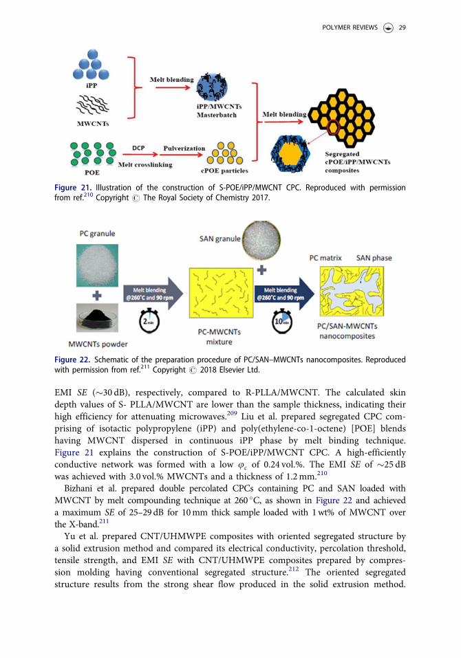
greater than that for the composites with no HGMs (25.27 dB) in the frequency rangebetween 8.0 and 12.0GHz (X-band). The porous composites showed better EMI shield-ing performance than the solid composites (Fig. 20a). It was observed that the incorpo-rated HGMs endorsed the interlink between conducting fillers along with the scatteringand reflection of the electromagnetic incident wave (Fig. 20b), that improved its EMISE.206 The segregated PVDF/MWCNT composites fabricated by mechanical mixing fol-lowed by hot compaction exhibited high electrical conductivity and EMI SE of 6 S m�1
and 30.89 dB with absorption as dominant mechanism in the X-band. A significantincrease in EMI SE was observed over the entire frequency range as the sample thick-ness increased from 0.6 to 3.0mm.207
Wang et al. demonstrated a morphological control of the MWCNT conducting net-work in two phasic blends of poly(L-lactide) [PLLA] and poly(e-caprolactone) [PCL] bythe formation of stereo-complex crystallites (SC) during melt processing. The compo-sites of (48PLLA þ12PDLA)/PCL/MWCNT containing 0.2 wt% and 0.8 wt% MWCNTs,displayed the EMI SE of about 7.2–11.4 dB and �17 dB, respectively. The improvedEMI shielding performance is mainly related to the enhanced electrical conductivity ofthe (48PLLA þ12PDLA)/PCL/MWCNT composites with co-continuous morphologyand the increased MWCNT loadings.208 However, the poor compatibility between thesetwo different polymers limits their mechanical properties. To address this problem, thesame research group constructed segregated CPCs with two polymers of the samemolecular structures and different viscosities. They prepared biodegradable with segre-gated PLLA/MWCNT nanocomposites (S-PLLA/MWCNT) using PLLA polymers of twodifferent viscosities and compared their EMI shielding performance with a randomPLLA/MWCNT nanocomposites (R-PLLA/MWCNT). The dimensional parameter value(t) of the threshold percolation equation for the S-PLLA/MWCNT and R-PLLA/MWCNT was found to be 1.63 and 3.89, respectively. Thus, S-PLLA/MWCNT exhibitedsuperior electrical conductivity at an ultra low uc of 0.019 vol.% than that of the R-PLLA/MWCNT (uc �0.22 vol.%). At 0.8 vol.% of MWCNT loading, S- PLLA/MWCNTdisplayed three orders and 36% higher values for electrical conductivity (25 S m�1) and
Figure 20. (a) Specific EMI SE (SSE) and (b) EMI Shielding mechanism of the P/CNT/HGM composites.Reproduced with permission from ref.206 Copyright # Springer Scienceþ Business Media, LLC, part ofSpringer Nature 2018.
28 D. JIANG ET AL.
EMI SE (�30 dB), respectively, compared to R-PLLA/MWCNT. The calculated skindepth values of S- PLLA/MWCNT are lower than the sample thickness, indicating theirhigh efficiency for attenuating microwaves.209 Liu et al. prepared segregated CPC com-prising of isotactic polypropylene (iPP) and poly(ethylene-co-1-octene) [POE] blendshaving MWCNT dispersed in continuous iPP phase by melt binding technique.Figure 21 explains the construction of S-POE/iPP/MWCNT CPC. A high-efficientlyconductive network was formed with a low uc of 0.24 vol.%. The EMI SE of �25 dBwas achieved with 3.0 vol.% MWCNTs and a thickness of 1.2mm.210
Bizhani et al. prepared double percolated CPCs containing PC and SAN loaded withMWCNT by melt compounding technique at 260 �C, as shown in Figure 22 and achieveda maximum SE of 25–29dB for 10mm thick sample loaded with 1wt% of MWCNT overthe X-band.211
Yu et al. prepared CNT/UHMWPE composites with oriented segregated structure bya solid extrusion method and compared its electrical conductivity, percolation threshold,tensile strength, and EMI SE with CNT/UHMWPE composites prepared by compres-sion molding having conventional segregated structure.212 The oriented segregatedstructure results from the strong shear flow produced in the solid extrusion method.
Figure 21. Illustration of the construction of S-POE/iPP/MWCNT CPC. Reproduced with permissionfrom ref.210 Copyright # The Royal Society of Chemistry 2017.
Figure 22. Schematic of the preparation procedure of PC/SAN–MWCNTs nanocomposites. Reproducedwith permission from ref.211 Copyright # 2018 Elsevier Ltd.
POLYMER REVIEWS 29
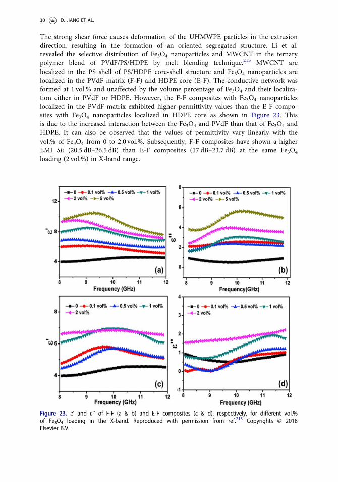
The strong shear force causes deformation of the UHMWPE particles in the extrusiondirection, resulting in the formation of an oriented segregated structure. Li et al.revealed the selective distribution of Fe3O4 nanoparticles and MWCNT in the ternarypolymer blend of PVdF/PS/HDPE by melt blending technique.213 MWCNT arelocalized in the PS shell of PS/HDPE core-shell structure and Fe3O4 nanoparticles arelocalized in the PVdF matrix (F-F) and HDPE core (E-F). The conductive network wasformed at 1 vol.% and unaffected by the volume percentage of Fe3O4 and their localiza-tion either in PVdF or HDPE. However, the F-F composites with Fe3O4 nanoparticleslocalized in the PVdF matrix exhibited higher permittivity values than the E-F compo-sites with Fe3O4 nanoparticles localized in HDPE core as shown in Figure 23. Thisis due to the increased interaction between the Fe3O4 and PVdF than that of Fe3O4 andHDPE. It can also be observed that the values of permittivity vary linearly with thevol.% of Fe3O4 from 0 to 2.0 vol.%. Subsequently, F-F composites have shown a higherEMI SE (20.5 dB–26.5 dB) than E-F composites (17 dB–23.7 dB) at the same Fe3O4
loading (2 vol.%) in X-band range.
Figure 23. e’ and e’’ of F-F (a & b) and E-F composites (c & d), respectively, for different vol.%of Fe3O4 loading in the X-band. Reproduced with permission from ref.213 Copyrights © 2018Elsevier B.V.
30 D. JIANG ET AL.
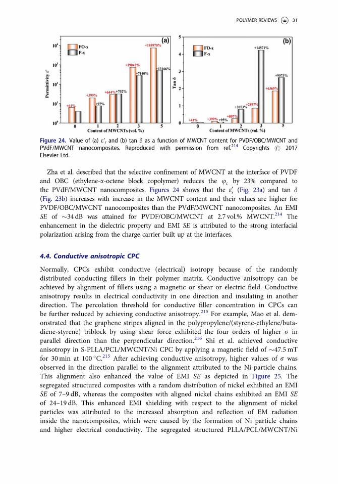
Zha et al. described that the selective confinement of MWCNT at the interface of PVDFand OBC (ethylene-a-octene block copolymer) reduces the uc by 23% compared tothe PVdF/MWCNT nanocomposites. Figures 24 shows that the e0r (Fig. 23a) and tan d(Fig. 23b) increases with increase in the MWCNT content and their values are higher forPVDF/OBC/MWCNT nanocomposites than the PVdF/MWCNT nanocomposites. An EMISE of �34 dB was attained for PVDF/OBC/MWCNT at 2.7 vol.% MWCNT.214 Theenhancement in the dielectric property and EMI SE is attributed to the strong interfacialpolarization arising from the charge carrier built up at the interfaces.
4.4. Conductive anisotropic CPC
Normally, CPCs exhibit conductive (electrical) isotropy because of the randomlydistributed conducting fillers in their polymer matrix. Conductive anisotropy can beachieved by alignment of fillers using a magnetic or shear or electric field. Conductiveanisotropy results in electrical conductivity in one direction and insulating in anotherdirection. The percolation threshold for conductive filler concentration in CPCs canbe further reduced by achieving conductive anisotropy.215 For example, Mao et al. dem-onstrated that the graphene stripes aligned in the polypropylene/(styrene-ethylene/buta-diene-styrene) triblock by using shear force exhibited the four orders of higher r inparallel direction than the perpendicular direction.216 Shi et al. achieved conductiveanisotropy in S-PLLA/PCL/MWCNT/Ni CPC by applying a magnetic field of �47.5 mTfor 30min at 100 �C.215 After achieving conductive anisotropy, higher values of r wasobserved in the direction parallel to the alignment attributed to the Ni-particle chains.This alignment also enhanced the value of EMI SE as depicted in Figure 25. Thesegregated structured composites with a random distribution of nickel exhibited an EMISE of 7–9 dB, whereas the composites with aligned nickel chains exhibited an EMI SEof 24–19 dB. This enhanced EMI shielding with respect to the alignment of nickelparticles was attributed to the increased absorption and reflection of EM radiationinside the nanocomposites, which were caused by the formation of Ni particle chainsand higher electrical conductivity. The segregated structured PLLA/PCL/MWCNT/Ni
Figure 24. Value of (a) e’r and (b) tan d as a function of MWCNT content for PVDF/OBC/MWCNT andPVdF/MWCNT nanocomposites. Reproduced with permission from ref.214 Copyrights # 2017Elsevier Ltd.
POLYMER REVIEWS 31
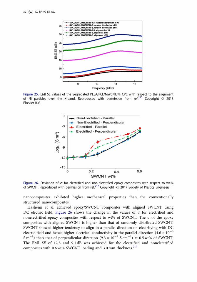
nanocomposites exhibited higher mechanical properties than the conventionallystructured nanocomposites.Hashemi et al. achieved epoxy/SWCNT composites with aligned SWCNT using
DC electric field. Figure 26 shows the change in the values of r for electrified andnonelectrified epoxy composites with respect to wt% of SWCNT. The r of the epoxycomposites with aligned SWCNT is higher than that of randomly distributed SWCNT.SWCNT showed higher tendency to align in a parallel direction on electrifying with DCelectric field and hence higher electrical conductivity in the parallel direction (4.6� 10�6
S.m�1) than that of perpendicular direction (9.3� 10�9 S.cm�1) at 0.5 wt% of SWCNT.The EMI SE of 12.8 and 9.1 dB was achieved for the electrified and nonelectrifiedcomposites with 0.6 wt% SWCNT loading and 3.0mm thickness.217
Figure 25. EMI SE values of the Segregated PLLA/PCL/MWCNT/Ni CPC with respect to the alignmentof Ni particles over the X-band. Reproduced with permission from ref.215 Copyright © 2018Elsevier B.V.
Figure 26. Deviation of r for electrified and non-electrified epoxy composites with respect to wt.%of SWCNT. Reproduced with permission from ref.217 Copyright # 2017 Society of Plastics Engineers.
32 D. JIANG ET AL.
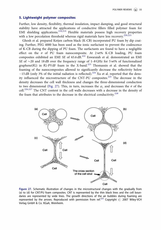
5. Lightweight polymer composites
Further, low density, flexibility, thermal insulation, impact damping, and good structuralstability have attracted the applications of conductive fillers filled polymer foam forEMI shielding applications.218,219 Flexible materials possess high recovery propertieswith a low percolation threshold whereas rigid materials have less recovery.220,221
Ghosh et al. prepared Ketjen carbon black (K-CB) incorporated PU foam by dip coat-ing. Further, PEG 4000 has been used as the ionic surfactant to prevent the coalescenceof K-CB during the dipping of PU foam. The surfactants are found to have a negligibleeffect on the r of PU foam nanocomposite. At 2wt% K-CB loading, PU foamcomposites exhibited an EMI SE of 65.6 dB.222 Eswaraiah et al. demonstrated an EMISE of �20 and 18 dB over the frequency range of 1–8GHz for 5wt% of functionalizedgraphene(fG) in fG-PVdF foam in the X-band.223 Thomassin et al. showed that thefoaming of the nanocomposites allowed to significantly decrease the reflectivity below�15 dB (only 3% of the initial radiation is reflected).224 Xu et al. reported that the dens-ity influenced the microstructure of the CNT-PU composites.225 The decrease in thedensity decreases the cell wall thickness and changes the three-dimensional conductionto two dimensional (Fig. 27). This, in turn, increases the uc and decreases the r of thecell.226,227 The CNT content in the cell walls decreases with a decrease in the density ofthe foam that attributes to the decrease in the electrical conductivity.228
Figure 27. Schematic illustration of changes in the microstructural changes with the gradually from(a) to (d) for CNT/PU foam composites. CNT is represented by the thin black lines and the cell boun-daries are represented by wide lines. The growth directions of the air bubbles during foaming arerepresented by the arrows. Reproduced with permission from ref.225 Copyright # 2007 Wiley-VCHVerlag GmbH & Co. KGaA, Weinheim.
POLYMER REVIEWS 33
Wang et al. compared the foaming behavior and EMI SE of PLA/graphite preparedby regular foam injection molding (RFIM) and mold-opening foam injection molding(MOFIM).229 The foams fabricated using the MOFIM method possess a uniform micro-cellular structure, whereas foams fabricated using the RFIM possess a collapsed micro-cellular structure. The EMI SE of the MOFIM foams is �45 dB, which is higher thanthat RFIM foams (�30 dB). Yang et al. reported that the CNT/PS and CNF/PS foamexhibited the EMI SE of 18.56 and 20.51 at 7 wt% and 20wt%, respectively.230 Chenet al. demonstrated that the 0.8 wt% graphene (GN) incorporated PDMS foam exhibitedthe nearly similar EMI SE (�20 dB) to the 7wt% of CNT incorporated polystyrenefoam.230,231 Xu et al. demonstrated that the CNT/HDPE foam exhibited an SET of21.2 dB at low uc of 1.66 vol.%, whereas solid CNT/HDPE required a higher CNT con-tent of about 2.31 vol.%.232 Yan et al. prepared porous graphene/polystyrene foams(GPS) using CaCo3 particles using compression molding followed by the salt-leachingmethod.233 The average EMI SE of the GPS samples of 2.5mm thickness at 0.45 and0.27 g.cm�3 are found to be approximately 29.3 and 17.3 dB, respectively. Zhang et al.demonstrated SET, SEA, and SER of 19, 18, and 1 dB, respectively, for 1.8 vol.% of GNloaded microcellular PMMA foam using subcritical CO2.
234 Zheng et al. prepared lowdensity (0.28–0.4 g/cm3) polyetherimide (PEI) composites containing GN@Fe3O4 byphase inversion method with outstanding specific shielding effectiveness (SSE) of�41.5 dB/(g/cm3) in the X-band at 10wt% loading.235 The excellent EMI SE attributedto the spherical micro-scale bubbles in the foam that can depreciate the EM waves byscattering and multi-internal reflection between the nanofillers and the cell walls. Inaddition, the micro-scale bubbles of the foam prevent the EM waves from escaping eas-ily before being attenuated by absorption and heat transfer as illustrated in Figure28a–b. TEM image (Fig. 28c) showing two parallel G@ Fe3O4 in PEI matrix supportsthe illustrated shielding mechanism of multi-internal reflection. The same researchgroup has also demonstrated a higher SE value of 57.7 dB for the 10wt% grapheneloaded PU foam of �6 cm thick. Also, the G/PU foams exhibited excellent compressibil-ity. It is also observed that their shielding performance can be modified by compressingthe foams. Figure 29 shows that the SET of the 6mm thick G(10wt.%)/PU foamdecreases with increasing the compression percentage. It can be observed that the SERremains almost the same for all compression rates, whereas SEA decreases. This can beascribed to the decrease in the cell-matrix interface area during compression that deteri-orates the multiple-internal reflection and scattering of EM waves.236
Ling et al. reported low-density microcellular PEI/GN foams with accumulation andalignment of graphene on the cell wall and SSE ranging from 17 to 44dB/(g/cm3).237
Zheng et al. assembled an aligned porous MWCNT/WPU composites with low and well-regulated densities by the unidirectional freeze-drying and demonstrated an outstandingSSE up to 1148dB cm3 g�1.238 Fu et al. fabricated self-healing hydrogel by dispersingMWCNT into the hydrophobic polyacrylamide (PAM) and demonstrated a SET of�28.5 dB. The cellulose nanofiber (CNF) is used as the dispersant. The prepared hydrogels(Fig. 30a) exhibited excellent capacity to withstand deformations such as convolving (Fig.30b), bending (Fig. 30c), knotting (Fig. 30d), and knotted stretching (Fig. 30e), withoutchange in its shape (Fig. 30f).239 However, since it is difficult to control the porous shapeby these preparation methods, the preparation of prevailing pores is still unsatisfactory.
34 D. JIANG ET AL.
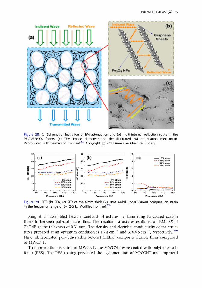
Xing et al. assembled flexible sandwich structures by laminating Ni-coated carbonfibers in between polycarbonate films. The resultant structures exhibited an EMI SE of72.7 dB at the thickness of 0.31mm. The density and electrical conductivity of the struc-tures prepared at an optimum condition is 1.7 g.cm�3 and 376.6 S.cm�1, respectively.240
Na et al. fabricated poly(ether ether ketone) (PEEK) composite flexible films comprisedof MWCNT.To improve the disperion of MWCNT, the MWCNT were coated with poly(ether sul-
fone) (PES). The PES coating prevented the agglomeration of MWCNT and improved
Figure 29. SET, (b) SEA, (c) SER of the 6mm thick G (10wt.%)/PU under various compression strainin the frequency range of 8–12GHz. Modified from ref.236
Figure 28. (a) Schematic illustration of EM attenuation and (b) multi-internal reflection route in thePEI/G@Fe3O4 foams; (c) TEM image demonstrating the illustrated EM attenuation mechanism.Reproduced with permission from ref.235 Copyright # 2013 American Chemical Society.
POLYMER REVIEWS 35
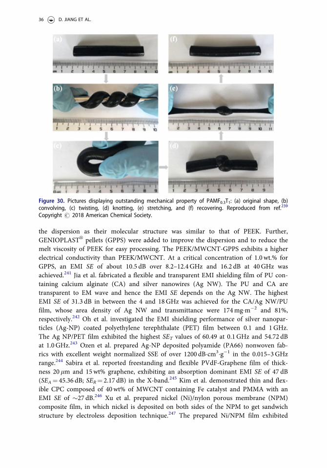
the dispersion as their molecular structure was similar to that of PEEK. Further,GENIOPLASTVR pellets (GPPS) were added to improve the dispersion and to reduce themelt viscosity of PEEK for easy processing. The PEEK/MWCNT-GPPS exhibits a higherelectrical conductivity than PEEK/MWCNT. At a critical concentration of 1.0 wt.% forGPPS, an EMI SE of about 10.5 dB over 8.2–12.4GHz and 16.2 dB at 40GHz wasachieved.241 Jia et al. fabricated a flexible and transparent EMI shielding film of PU con-taining calcium alginate (CA) and silver nanowires (Ag NW). The PU and CA aretransparent to EM wave and hence the EMI SE depends on the Ag NW. The highestEMI SE of 31.3 dB in between the 4 and 18GHz was achieved for the CA/Ag NW/PUfilm, whose area density of Ag NW and transmittance were 174mgm�2 and 81%,respectively.242 Oh et al. investigated the EMI shielding performance of silver nanopar-ticles (Ag-NP) coated polyethylene terephthalate (PET) film between 0.1 and 1GHz.The Ag NP/PET film exhibited the highest SET values of 60.49 at 0.1GHz and 54.72 dBat 1.0GHz.243 Ozen et al. prepared Ag-NP deposited polyamide (PA66) nonwoven fab-rics with excellent weight normalized SSE of over 1200 dBcm3g�1 in the 0.015–3GHzrange.244 Sabira et al. reported freestanding and flexible PVdF-Graphene film of thick-ness 20 lm and 15wt% graphene, exhibiting an absorption dominant EMI SE of 47 dB(SEA¼ 45.36 dB; SER¼ 2.17 dB) in the X-band.245 Kim et al. demonstrated thin and flex-ible CPC composed of 40wt% of MWCNT containing Fe catalyst and PMMA with anEMI SE of �27 dB.246 Xu et al. prepared nickel (Ni)/nylon porous membrane (NPM)composite film, in which nickel is deposited on both sides of the NPM to get sandwichstructure by electroless deposition technique.247 The prepared Ni/NPM film exhibited
Figure 30. Pictures displaying outstanding mechanical property of PAMF0.3T1: (a) original shape, (b)convolving, (c) twisting, (d) knotting, (e) stretching, and (f) recovering. Reproduced from ref.239
Copyright # 2018 American Chemical Society.
36 D. JIANG ET AL.
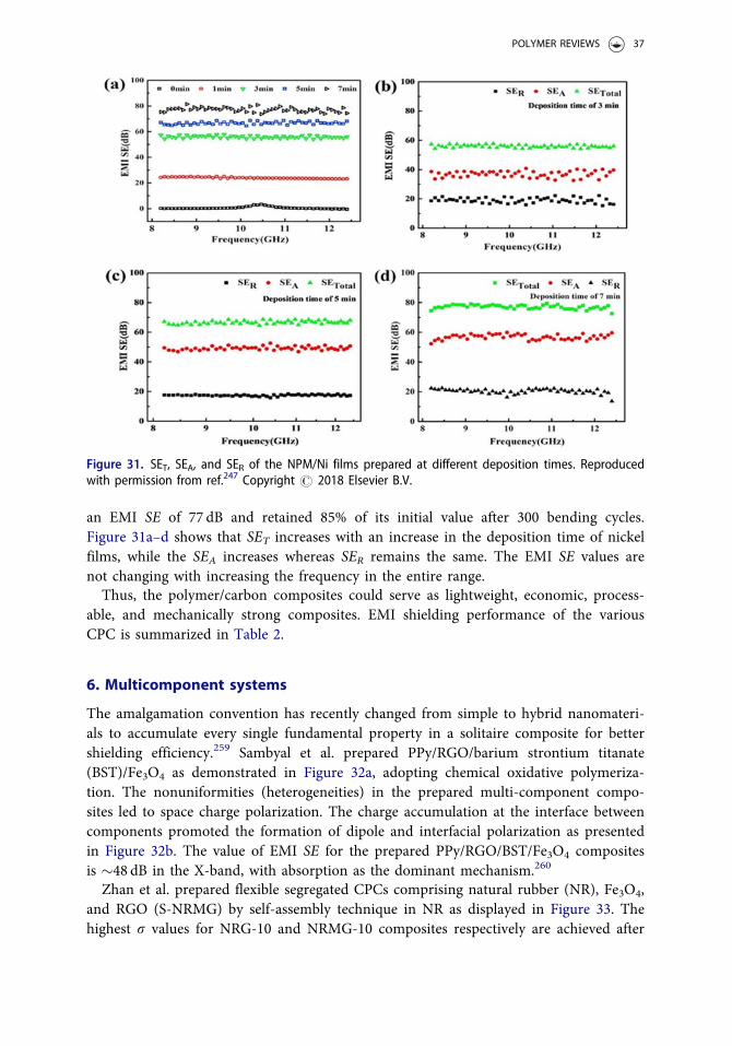
an EMI SE of 77 dB and retained 85% of its initial value after 300 bending cycles.Figure 31a–d shows that SET increases with an increase in the deposition time of nickelfilms, while the SEA increases whereas SER remains the same. The EMI SE values arenot changing with increasing the frequency in the entire range.Thus, the polymer/carbon composites could serve as lightweight, economic, process-
able, and mechanically strong composites. EMI shielding performance of the variousCPC is summarized in Table 2.
6. Multicomponent systems
The amalgamation convention has recently changed from simple to hybrid nanomateri-als to accumulate every single fundamental property in a solitaire composite for bettershielding efficiency.259 Sambyal et al. prepared PPy/RGO/barium strontium titanate(BST)/Fe3O4 as demonstrated in Figure 32a, adopting chemical oxidative polymeriza-tion. The nonuniformities (heterogeneities) in the prepared multi-component compo-sites led to space charge polarization. The charge accumulation at the interface betweencomponents promoted the formation of dipole and interfacial polarization as presentedin Figure 32b. The value of EMI SE for the prepared PPy/RGO/BST/Fe3O4 compositesis �48 dB in the X-band, with absorption as the dominant mechanism.260
Zhan et al. prepared flexible segregated CPCs comprising natural rubber (NR), Fe3O4,and RGO (S-NRMG) by self-assembly technique in NR as displayed in Figure 33. Thehighest r values for NRG-10 and NRMG-10 composites respectively are achieved after
Figure 31. SET, SEA, and SER of the NPM/Ni films prepared at different deposition times. Reproducedwith permission from ref.247 Copyright # 2018 Elsevier B.V.
POLYMER REVIEWS 37
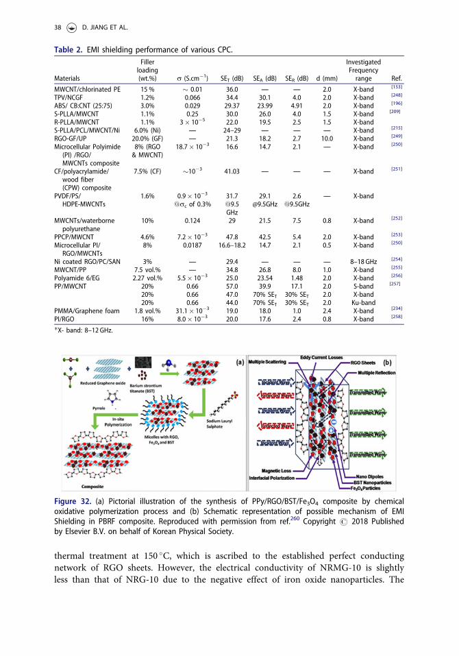
thermal treatment at 150 �C, which is ascribed to the established perfect conductingnetwork of RGO sheets. However, the electrical conductivity of NRMG-10 is slightlyless than that of NRG-10 due to the negative effect of iron oxide nanoparticles. The
Table 2. EMI shielding performance of various CPC.
Materials
Fillerloading(wt.%) r (S.cm�1) SET (dB) SEA (dB) SER (dB) d (mm)
InvestigatedFrequencyrange Ref.
MWCNT/chlorinated PE 15 % � 0.01 36.0 — — 2.0 X-band [153]
TPV/NCGF 1.2% 0.066 34.4 30.1 4.0 2.0 X-band [248]
ABS/ CB:CNT (25:75) 3.0% 0.029 29.37 23.99 4.91 2.0 X-band [196]
S-PLLA/MWCNT 1.1% 0.25 30.0 26.0 4.0 1.5 X-band [209]
R-PLLA/MWCNT 1.1% 3� 10�5 22.0 19.5 2.5 1.5 X-bandS-PLLA/PCL/MWCNT/Ni 6.0% (Ni) — 24–29 — — — X-band [215]
RGO-GF/UP 20.0% (GF) — 21.3 18.2 2.7 10.0 X-band [249]
Microcellular Polyimide(PI) /RGO/MWCNTs composite
8% (RGO& MWCNT)
18.7� 10�3 16.6 14.7 2.1 — X-band [250]
CF/polyacrylamide/wood fiber(CPW) composite
7.5% (CF) �10�3 41.03 — — — X-band [251]
PVDF/PS/HDPE-MWCNTs
1.6% 0.9� 10�3
@rc of 0.3%[email protected]
— X-band
MWCNTs/waterbornepolyurethane
10% 0.124 29 21.5 7.5 0.8 X-band [252]
PPCP/MWCNT 4.6% 7.2� 10�3 47.8 42.5 5.4 2.0 X-band [253]
Microcellular PI/RGO/MWCNTs
8% 0.0187 16.6–18.2 14.7 2.1 0.5 X-band [250]
Ni coated RGO/PC/SAN 3% — 29.4 — — — 8–18 GHz [254]
MWCNT/PP 7.5 vol.% — 34.8 26.8 8.0 1.0 X-band [255]
Polyamide 6/EG 2.27 vol.% 5.5� 10�3 25.0 23.54 1.48 2.0 X-band [256]
PP/MWCNT 20% 0.66 57.0 39.9 17.1 2.0 S-band [257]
20% 0.66 47.0 70% SET 30% SET 2.0 X-band20% 0.66 44.0 70% SET 30% SET 2.0 Ku-band
PMMA/Graphene foam 1.8 vol.% 31.1� 10�3 19.0 18.0 1.0 2.4 X-band [234]
PI/RGO 16% 8.0� 10�3 20.0 17.6 2.4 0.8 X-band [258]
�X- band: 8–12 GHz.
Figure 32. (a) Pictorial illustration of the synthesis of PPy/RGO/BST/Fe3O4 composite by chemicaloxidative polymerization process and (b) Schematic representation of possible mechanism of EMIShielding in PBRF composite. Reproduced with permission from ref.260 Copyright # 2018 Publishedby Elsevier B.V. on behalf of Korean Physical Society.
38 D. JIANG ET AL.
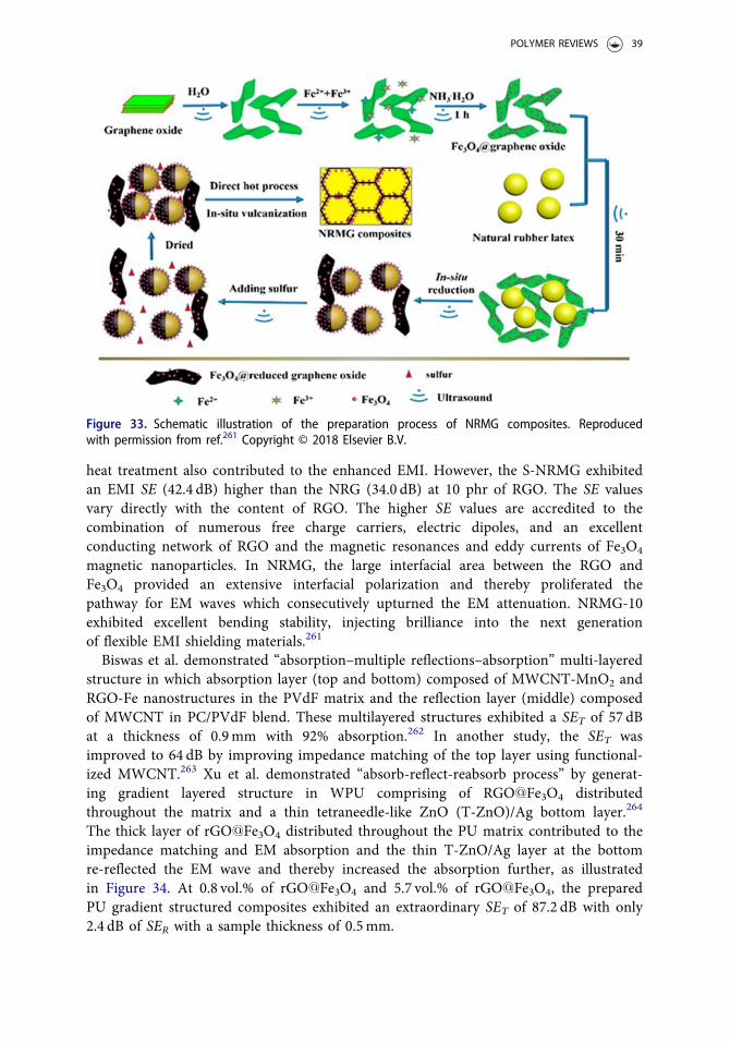
heat treatment also contributed to the enhanced EMI. However, the S-NRMG exhibitedan EMI SE (42.4 dB) higher than the NRG (34.0 dB) at 10 phr of RGO. The SE valuesvary directly with the content of RGO. The higher SE values are accredited to thecombination of numerous free charge carriers, electric dipoles, and an excellentconducting network of RGO and the magnetic resonances and eddy currents of Fe3O4
magnetic nanoparticles. In NRMG, the large interfacial area between the RGO andFe3O4 provided an extensive interfacial polarization and thereby proliferated thepathway for EM waves which consecutively upturned the EM attenuation. NRMG-10exhibited excellent bending stability, injecting brilliance into the next generationof flexible EMI shielding materials.261
Biswas et al. demonstrated “absorption–multiple reflections–absorption” multi-layeredstructure in which absorption layer (top and bottom) composed of MWCNT-MnO2 andRGO-Fe nanostructures in the PVdF matrix and the reflection layer (middle) composedof MWCNT in PC/PVdF blend. These multilayered structures exhibited a SET of 57 dBat a thickness of 0.9mm with 92% absorption.262 In another study, the SET wasimproved to 64 dB by improving impedance matching of the top layer using functional-ized MWCNT.263 Xu et al. demonstrated “absorb-reflect-reabsorb process” by generat-ing gradient layered structure in WPU comprising of RGO@Fe3O4 distributedthroughout the matrix and a thin tetraneedle-like ZnO (T-ZnO)/Ag bottom layer.264
The thick layer of rGO@Fe3O4 distributed throughout the PU matrix contributed to theimpedance matching and EM absorption and the thin T-ZnO/Ag layer at the bottomre-reflected the EM wave and thereby increased the absorption further, as illustratedin Figure 34. At 0.8 vol.% of rGO@Fe3O4 and 5.7 vol.% of rGO@Fe3O4, the preparedPU gradient structured composites exhibited an extraordinary SET of 87.2 dB with only2.4 dB of SER with a sample thickness of 0.5mm.
Figure 33. Schematic illustration of the preparation process of NRMG composites. Reproducedwith permission from ref.261 Copyright © 2018 Elsevier B.V.
POLYMER REVIEWS 39
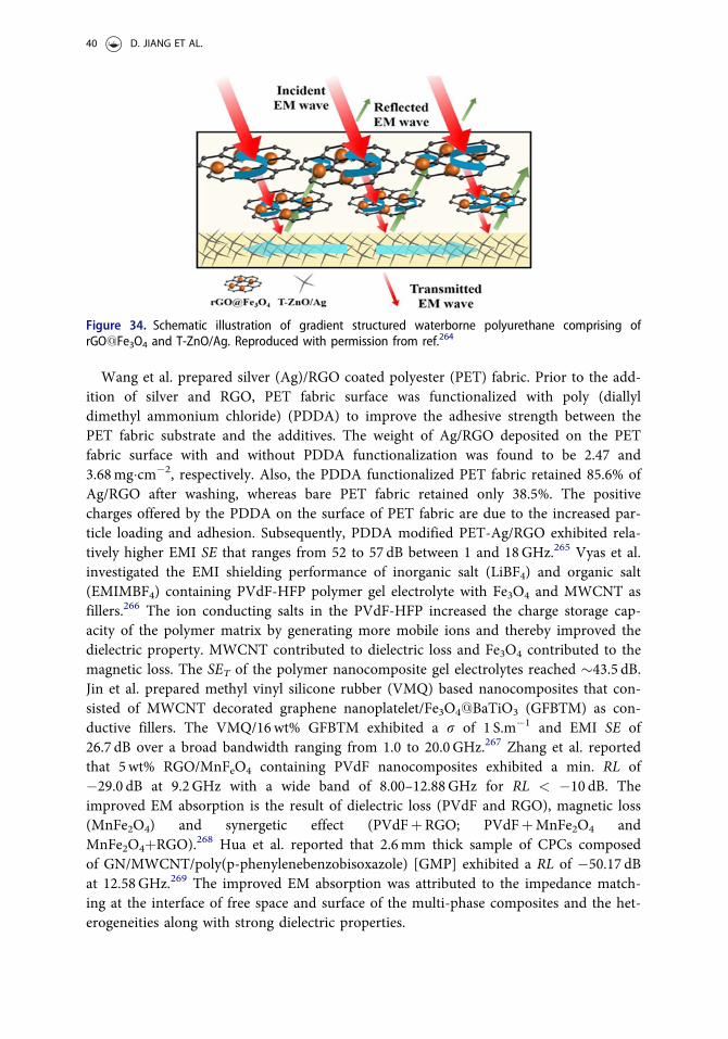
Wang et al. prepared silver (Ag)/RGO coated polyester (PET) fabric. Prior to the add-ition of silver and RGO, PET fabric surface was functionalized with poly (diallyldimethyl ammonium chloride) (PDDA) to improve the adhesive strength between thePET fabric substrate and the additives. The weight of Ag/RGO deposited on the PETfabric surface with and without PDDA functionalization was found to be 2.47 and3.68mgcm�2, respectively. Also, the PDDA functionalized PET fabric retained 85.6% ofAg/RGO after washing, whereas bare PET fabric retained only 38.5%. The positivecharges offered by the PDDA on the surface of PET fabric are due to the increased par-ticle loading and adhesion. Subsequently, PDDA modified PET-Ag/RGO exhibited rela-tively higher EMI SE that ranges from 52 to 57 dB between 1 and 18GHz.265 Vyas et al.investigated the EMI shielding performance of inorganic salt (LiBF4) and organic salt(EMIMBF4) containing PVdF-HFP polymer gel electrolyte with Fe3O4 and MWCNT asfillers.266 The ion conducting salts in the PVdF-HFP increased the charge storage cap-acity of the polymer matrix by generating more mobile ions and thereby improved thedielectric property. MWCNT contributed to dielectric loss and Fe3O4 contributed to themagnetic loss. The SET of the polymer nanocomposite gel electrolytes reached �43.5 dB.Jin et al. prepared methyl vinyl silicone rubber (VMQ) based nanocomposites that con-sisted of MWCNT decorated graphene nanoplatelet/Fe3O4@BaTiO3 (GFBTM) as con-ductive fillers. The VMQ/16wt% GFBTM exhibited a r of 1 S.m�1 and EMI SE of26.7 dB over a broad bandwidth ranging from 1.0 to 20.0GHz.267 Zhang et al. reportedthat 5wt% RGO/MnFeO4 containing PVdF nanocomposites exhibited a min. RL of�29.0 dB at 9.2GHz with a wide band of 8.00–12.88GHz for RL < �10 dB. Theimproved EM absorption is the result of dielectric loss (PVdF and RGO), magnetic loss(MnFe2O4) and synergetic effect (PVdFþRGO; PVdFþMnFe2O4 andMnFe2O4þRGO).268 Hua et al. reported that 2.6mm thick sample of CPCs composedof GN/MWCNT/poly(p-phenylenebenzobisoxazole) [GMP] exhibited a RL of �50.17 dBat 12.58GHz.269 The improved EM absorption was attributed to the impedance match-ing at the interface of free space and surface of the multi-phase composites and the het-erogeneities along with strong dielectric properties.
Figure 34. Schematic illustration of gradient structured waterborne polyurethane comprising ofrGO@Fe3O4 and T-ZnO/Ag. Reproduced with permission from ref.264
40 D. JIANG ET AL.
7 Conclusion and future perspectives
Recent advances in EMI shielding using ICP and CPC have clearly indicated that polymersand their hybrids/multi-structural composites are very promising for EMI shielding applica-tions. The frequency-dependent characteristics, as well as the adjustment of the morpho-logical structure and processing parameters, are discussed to achieve enhanced EMIshielding along with to understand its corresponding mechanisms. It is worth mentioningthat all of these studies aim to introduce nonuniformities (heterogeneities) inside the EMIshielding materials to enhance EM absorption. In the case of biphasic polymer blends,engineering of filler localization and morphology greatly improved the EM absorption. Theattractive features of the polymer-based materials such as lightweight and high EM absorp-tion demonstrated their potentials in EMI shielding.Despite considerable advancements, they face many obvious challenges. The significant
limitations include: Insulating nature of polymers that may lead to the enlargement of skindepth for EM attenuation (if sufficient conducting network is not established by theconductive fillers); Difficult in processing and reconstruction of defects; Surface-functionalization of fillers that harms the physical properties of the composites and proc-essing; Poor thermal stability that hinders their applications in high-temperature operation;Understanding the thermodynamics of polymer blends and corresponding preferentiallocalization of fillers; tailoring of morphology and physical properties of the fillers, etc.Even though, multi-component structures and lightweight foams are reported as efficientEM absorbers, the factors that determine their bandwidth of EM absorption and skindepth are still not clearly explained and it is not clear how the temperature influences theelectromagnetic properties of materials in the nanoscale polymer nanocomposites or nano-hybrids. Hence, more investigations are needed in this direction. However, we envisionthat light-weight multi-component nanostructures and three-dimensional architectures ofpolymer-based materials with good mechanical properties and high thermal stability willlead toward the realization of highly efficient EMI shielding for various applications.
Acknowledgments
The authors appreciate the supports from Heilongjiang Natural Science Foundation (QC2017038),Fundamental Research Funds for the Central Universities (No. 2572018BC27), China PostdoctoralScience Foundation (No. 2016M601402) Heilongjiang Postdoctoral Fund (No. LBH-Z16004, LBH-Z16089). Mr. MV is grateful to the Indo-US Science and Technology Forum (IUSSTF),Department of Science and Technology (DST), New Delhi for providing a fellowship under BASEprogram (IUSSTF BASE Internships 2018/12/Vignesh M, dt. 09/04/2018).
References
1. Gurusiddesh, M.; Madhu, B. J.; Shankaramurthy, G. J. Structural, Dielectric, Magnetic andElectromagnetic Interference Shielding Investigations of Polyaniline DecoratedCo0.5Ni0.5Fe2O4 Nanoferrites. J. Mater. Sci: Mater. Electron. 2018, 29, 3502–3509. doi:10.1007/s10854-017-8285-4.
2. Gong, S.; Zhu Zheng, H.; Arjmand, M.; Sundararaj, U.; Yeow, J.; T. W.; Zheng, W. Effectof Carbon Nanotubes on Electromagnetic Interference Shielding of Carbon FiberReinforced Polymer Composites. Polym. Compos. 2018, 39, E655–E663. doi:10.1002/pc.24084.
POLYMER REVIEWS 41
3. Biao, Z.; Deng, J.; Zhang, R.; Liang, L.; Fan, B.; Bai, Z.; Shao, G.; Park, C. B. RecentAdvances on the Electromagnetic Wave Absorption Properties of Ni Based Materials.Eng.Sci. doi: 2018, 3, 5–40. doi:10.30919/es8d735.
4. Li, T.-T.; Chen, A.-P.; Hwang, P.-W.; Pan, Y.-J.; Hsing, W.-H.; Lou, C.-W.; Chen, Y.-S.;Lin, J.-H. Synergistic Effects of Micro-/Nano-fillers on Conductive and ElectromagneticShielding Properties of Polypropylene Nanocomposites. Mater. Manuf. Processes 2018, 33,149–155. doi:10.1080/10426914.2016.1269924.
5. Engels, S.; Schneider, N.-L.; Lefeldt, N.; Hein, C. M.; Zapka, M.; Michalik, A.; Elbers, D.;Kittel, A.; Hore, P. J.; Mouritsen, H. Anthropogenic Electromagnetic Noise DisruptsMagnetic Compass Orientation in a Migratory Bird. Nature 2014, 509, 353. doi:10.1038/nature13290.
6. Erogul, O.; Oztas, E.; Yildirim, I.; Kir, T.; Aydur, E.; Komesli, G.; Irkilata, H. C.; Irmak,M. K.; Peker, A. F. Effects of Electromagnetic Radiation from a Cellular Phone on HumanSperm Motility: An in Vitro Study. Arch. Med. Res. 2006, 37, 840–843. doi:10.1016/j.arcmed.2006.05.003.
7. Ding, Z.; Shi, S. Q.; Zhang, H.; Cai, L. Electromagnetic Shielding Properties of Iron OxideImpregnated Kenaf Bast Fiberboard. Composites, Part B. 2015, 78, 266–271. doi:10.1016/j.compositesb.2015.03.044.
8. Tang, H.; Jian, X.; Wu, B.; Liu, S.; Jiang, Z.; Chen, X.; Lv, W.; He, W.; Tian, W.; Wei, Y.;et al. Fe3C/helical Carbon Nanotube Hybrid: Facile Synthesis and Spin-InducedEnhancement in Microwave-absorbing Properties. Composites, Part B 2016, 107, 51–58.doi:10.1016/j.compositesb.2016.09.003.
9. Tugirumubano, A.; Vijay, S. J.; Go, S. H.; Kwac, L. K.; Kim, H. G. Investigation ofMechanical and Electromagnetic Interference Shielding Properties of Nickel–CFRP TextileComposites. J. Mater. Eng. Perform. 2018, 27, 2255–2262. doi:10.1007/s11665-018-3334-6.
10. Bhawal, P.; Ganguly, S.; Das Tushar, K.; Mondal, S.; Das, N. C. Mechanically RobustConductive Carbon Clusters Confined Ethylene Methyl Acrylate–based FlexibleComposites for Superior Shielding Effectiveness. Polym. Adv. Technol. 2018, 29, 95–110.doi:10.1002/pat.4092.
11. Sawai, P.; Chattopadhaya, P. P.; Banerjee, S. Synthesized Reduce Graphene Oxide (rGO)Filled Polyetherimide Based Nanocomposites for EMI Shielding Applications. Mater.Today: Proc. 2018, 5, 9989–9999. doi:10.1016/j.matpr.2017.10.197.
12. Singh, A. K.; Shishkin, A.; Koppel, T.; Gupta, N. A Review of Porous LightweightComposite Materials for Electromagnetic Interference Shielding. Comp., Part B 2018, 149,188–197. doi:10.1016/j.compositesb.2018.05.027.
13. Huang, J.-C. EMI Shielding Plastics: A Review. Adv. Polym. Technol. 1995, 14, 137–150.doi:10.1002/adv.1995.060140205.
14. Zhang, Y.; Wang, X.; Cao, M. Confinedly Implanted NiFe2O4-rGO: Cluster Tailoring andHighly Tunable Electromagnetic Properties for Selective-frequency Microwave Absorption.Nano Res. 2018, 11, 1426–1436. doi:10.1007/s12274-017-1758-1.
15. Xiang, C.; Pan, Y.; Liu, X.; Sun, X.; Shi, X.; Guo, J. Microwave Attenuation of MultiwalledCarbon Nanotube-fused Silica Composites. Appl. Phys. Lett. 2005, 87, 123103. doi:10.1063/1.2051806.
16. Cao, M.-S.; Wang, X.-X.; Cao, W.-Q.; Yuan, J. Ultrathin Graphene: Electrical Propertiesand Highly Efficient Electromagnetic Interference Shielding. J. Mater. Chem. C. 2015, 3,6589–6599. doi:10.1039/C5TC01354B.
17. Yang, C. C.; Gung, Y. J.; Hung, W. C.; Ting, T. H.; Wu, K. H. Infrared and MicrowaveAbsorbing Properties of BaTiO3/polyaniline and BaFe12O19/polyaniline Composites.Compos. Sci. Technol. 2010, 70, 466–471. doi:10.1016/j.compscitech.2009.11.021.
18. Luo, C.; Duan, W.; Yin, X.; Kong, J. Microwave-Absorbing Polymer-Derived Ceramicsfrom Cobalt-Coordinated Poly(dimethylsilylene)Diacetylenes. J. Phys. Chem. C. 2016, 120,18721–18732. doi:10.1021/acs.jpcc.6b03995.
42 D. JIANG ET AL.
19. Jiang, X.; Li, S.; He, S.; Bai, Y.; Shao, L. Interface Manipulation of CO2–philic CompositeMembranes Containing Designed UiO-66 Derivatives towards Highly Efficient CO2
Capture. J. Mater. Chem. A. 2018, 6, 15064–15073. doi:10.1039/C8TA03872D.20. Song, Y.; He, L.; Zhang, X.; Liu, F.; Tian, N.; Tang, Y.; Kong, J. Highly Efficient
Electromagnetic Wave Absorbing Metal-Free and Carbon-Rich Ceramics Derived fromHyperbranched Polycarbosilazanes. J. Phys. Chem. C. 2017, 121, 24774–24785. doi:10.1021/acs.jpcc.7b07646.
21. Sun, H.; Yang, X.; Zhang, Y.; Cheng, X.; Xu, Y.; Bai, Y.; Shao, L. Segregation-Induced inSitu Hydrophilic Modification of Poly (vinylidene Fluoride) ultrafiltration Membranes viaSticky Poly (ethylene Glycol) Blending. J. Membr. Sci. 2018, 563, 22–30. doi:10.1016/j.memsci.2018.05.046.
22. Yang, X.; Wang, Z.; Shao, L. Construction of Oil-unidirectional Membrane for IntegratedOil Collection with Lossless Transportation and Oil-in-water Emulsion Purification. J.Membr. Sci. 2018, 549, 67–74. doi:10.1016/j.memsci.2017.11.071.
23. Gu, J.; Li, Y.; Liang, C.; Tang, Y.; Tang, L.; Zhang, Y.; Kong, J.; Liu, H.; Guo, Z.Synchronously Improved Dielectric and Mechanical Properties of Wave-transparentLaminated Composites Combined with Outstanding Thermal Stability by IncorporatingIysozyme/POSS Functionalized PBO Fibers. J. Mater. Chem. C 2018, 6, 7652–7660. doi:10.1039/C8TC02391C.
24. Wu, N.; Liu, C.; Xu, D.; Liu, J.; Liu, W.; Shao, Q.; Guo, Z. Enhanced ElectromagneticWave Absorption of Three-Dimensional Porous Fe3O4/C Composite Flowers. ACSSustainable Chem. Eng. 2018, 6, 12471–12480. doi:10.1021/acssuschemeng.8b03097.
25. Cao, M.; Han, C.; Wang, X.; Zhang, M.; Zhang, Y.; Shu, J.; Yang, H.; Fang, X.; Yuan, J.Graphene Nanohybrids: excellent Electromagnetic Properties for the Absorbing andShielding of Electromagnetic Waves. J. Mater. Chem. C. 2018, 6, 4586–4602. doi:10.1039/C7TC05869A.
26. Ren, F.; Guo, Z.-Z.; Guo, H.; Jia, L.-C.; Zhao, Y.-C.; Ren, P.-G.; Yan, D.-X. Layer-Structured Design and Fabrication of Cyanate Ester Nanocomposites for ExcellentElectromagnetic Shielding with Absorption-Dominated Characteristic. Polymers 2018, 10,933.
27. Zhou, S.; Wang, J.; Wang, S.; Ma, X.; Huang, J.; Zhao, G.; Liu, Y. Facile Preparation ofMultiscale Graphene-basalt Fiber Reinforcements and Their Enhanced Mechanical andTribological Properties for Polyamide 6 Composites. Mater. Chem. Phys. 2018, 217,315–322. doi:10.1016/j.matchemphys.2018.06.080.
28. Wang, C.; Murugadoss, V.; Kong, J.; He, Z.; Mai, X.; Shao, Q.; Chen, Y.; Guo, L.; Liu, C.;Angaiah, S.; Guo, Z. Overview of Carbon Nanostructures and Nanocomposites forElectromagnetic Wave Shielding. Carbon 2018, 140, 696–733. doi:10.1016/j.carbon.2018.09.006.
29. Yang, Z.; Hao, X.; Chen, S.; Ma, Z.; Wang, W.; Wang, C.; Yue, L.; Sun, H.; Shao, Q.;Murugadoss, V.; Guo, Z. Long-term Antibacterial Stable Reduced Graphene OxideNanocomposites Loaded with Cuprous Oxide Nanoparticles. J. Colloid Interface Sci. 2019,533, 13–23. doi:10.1016/j.jcis.2018.08.053.
30. Ren, F.; Guo, Z.; Shi, Y.; Jia, L.; Qing, Y.; Ren, P.; Yan, D. Lightweight and HighlyEfficient Electromagnetic Wave-absorbing of 3D CNTs/GNS@CoFe2O4 TernaryComposite Aerogels. J. Alloys Compd. 2018, 768, 6–14. doi:10.1016/j.jallcom.2018.07.209.
31. Wu, H.-Y.; Zhang, Y.-P.; Jia, L.-C.; Yan, D.-X.; Gao, J.-F.; Li, Z.-M. Injection MoldedSegregated Carbon Nanotube/Polypropylene Composite for Efficient ElectromagneticInterference Shielding. Ind. Eng. Chem. Res. 2018, 57, 12378–12385. doi:10.1021/acs.iecr.8b02293.
32. Jia, L.-C.; Yan, D.-X.; Jiang, X.; Pang, H.; Gao, J.-F.; Ren, P.-G.; Li, Z.-M. SynergisticEffect of Graphite and Carbon Nanotubes on Improved Electromagnetic InterferenceShielding Performance in Segregated Composites. Ind. Eng. Chem. Res. 2018, 57,11929–11938. doi:10.1021/acs.iecr.8b03238.
POLYMER REVIEWS 43
33. Li, M.-Z.; Jia, L.-C.; Zhang, X.-P.; Yan, D.-X.; Zhang, Q.-C.; Li, Z.-M. Robust CarbonNanotube Foam for Efficient Electromagnetic Interference Shielding and MicrowaveAbsorption. J. Colloid Interface Sci. 2018, 530, 113–119. doi:10.1016/j.jcis.2018.06.052.
34. Yu, H.; Wang, T.; Wen, B.; Lu, M.; Xu, Z.; Zhu, C.; Chen, Y.; Xue, X.; Sun, C.; Cao, M.Graphene/polyaniline Nanorod Arrays: Synthesis and Excellent ElectromagneticAbsorption Properties. J. Mater. Chem. 2012, 22, 21679–21685. doi:10.1039/c2jm34273a.
35. Bera, R.; Maitra, A.; Paria, S.; Karan, S. K.; Das, A. K.; Bera, A.; Si, S. K.; Halder, L.; De,A.; Khatua, B. B. An Approach to Widen the Electromagnetic Shielding Efficiency inPDMS/ferrous Ferric Oxide Decorated RGO-SWCNH Composite through PressureInduced Tunability. Chem. Eng. J. 2018, 335, 501–509. doi:10.1016/j.cej.2017.10.178.
36. Song, W.-L.; Cao, M.-S.; Lu, M.-M.; Bi, S.; Wang, C.-Y.; Liu, J.; Yuan, J.; Fan, L.-Z.Flexible Graphene/polymer Composite Films in Sandwich Structures for EffectiveElectromagnetic Interference Shielding. Carbon 2014, 66, 67–76. doi:10.1016/j.carbon.2013.08.043.
37. Chen, Y.-H.; Huang, C.-Y.; Roan, M.-L.; Lai, F.-D.; Chen, K.-N.; Yeh, J.-T. The CopperSulfide Coating on Polyacrylonitrile with a Chelating Agent of EthylenediaminetetraaceticAcid by an Electroless Deposition Method and Its EMI Shielding Effectiveness. J. Appl.Polym. Sci. 2010, 115, 570–578. doi:10.1002/app.31009.
38. Onar, N.; Aks¸It, A. C.; Ebeoglugil, M. F.; Birlik, I.; Celik, E.;.; Ozdemir, I. Structural,Electrical, and Electromagnetic Properties of Cotton Fabrics Coated with Polyaniline andPolypyrrole. J. Appl. Polym. Sci. 2009, 114, 2003–2010. doi:10.1002/app.30652.
39. Wang, C.; Zhao, M.; Li, J.; Yu, J.; Sun, S.; Ge, S.; Guo, X.; Xie, F.; Jiang, B.; Wujcik, E. K.;et al. Silver Nanoparticles/Graphene Oxide Decorated Carbon Fiber SynergisticReinforcement in Epoxy-Based Composites. Polym. 2017, 131, 263–271. doi:10.1016/j.polymer.2017.10.049.
40. Kuang, T.; Chang, L.; Chen, F.; Sheng, Y.; Fu, D.; Peng, X. Facile Preparation ofLightweight High-strength Biodegradable Polymer/multi-walled Carbon NanotubesNanocomposite Foams for Electromagnetic Interference Shielding. Carbon 2016, 105,305–313. doi:10.1016/j.carbon.2016.04.052.
41. Nam, Y.-W.; Sathish Kumar, S. K.; Ankem, V. A.; Kim, C.-G. Multi-functional Aramid/Epoxy Composite for Stealth Space Hypervelocity Impact Shielding System. Compos.Struct. 2018, 193, 113–120. doi:10.1016/j.compstruct.2018.03.046.
42. Gyergyek, S.; Pahovnik, D.; �Zagar, E.; Mertelj, A.; Kostanj�sek, R.; Bekovi�c, M.; Jagodi�c, M.;Hofmann, H.; Makovec, D. Nanocomposites Comprised of Homogeneously DispersedMagnetic Iron-oxide Nanoparticles and Poly(methyl Methacrylate). Beilstein J.Nanotechnol. 2018, 9, 1613–1622. doi:10.3762/bjnano.9.153.
43. Li, Y.; Jing, T.; Xu, G.; Tian, J.; Dong, M.; Shao, Q.; Wang, B.; Wang, Z.; Zheng, Y.; Yang,C.; Guo, Z. 3-D Magnetic Graphene Oxide-Magnetite Poly(vinyl Alcohol) NanocompositeSubstrates for Immobilizing Enzyme. Polym 2018, 149, 13–22. doi:10.1016/j.polymer.2018.06.046.
44. Sun, Y.; Luo, S.; Sun, H.; Zeng, W.; Ling, C.; Chen, D.; Chan, V.; Liao, K. EngineeringClosed-Cell Structure in Lightweight and Flexible Carbon Foam Composite for High-Efficient Electromagnetic Interference Shielding. Carbon 2018, 136, 299–308. doi:10.1016/j.carbon.2018.04.084.
45. Muzaffar, A.; Ahamed, M. B.; Deshmukh, K.; Faisal, M.; Pasha, S. K. K. EnhancedElectromagnetic Absorption in NiO and BaTiO3 Based PolyvinylidenefluorideNanocomposites. Mater. Lett. 2018, 218, 217–220. doi:10.1016/j.matlet.2018.02.029.
46. Jana, P. B.; Mallick, A. K.; De, S. K. Effects of Sample Thickness and Fiber Aspect Ratioon EMI Shielding Effectiveness of Carbon Fiber Filled Polychloroprene Composites in theX-band Frequency Range. IEEE Trans. Electromagn. Compat. 1992, 34, 478–481. doi:10.1109/15.179281.
47. Lv, L.; Liu, J.; Liu, H.; Liu, C.; Lu, Y.; Sun, K.; Fan, R.; Wang, N.; Lu, N.; Guo, Z.; Wujcik,E. K. An Overview of Electrically Conductive Polymer Nanocomposites towardElectromagnetic Interference Shielding. Eng. Sci. 2018, 2, 26–42. doi:10.30919/es8d615.
44 D. JIANG ET AL.
48. Geetha, S.; Satheesh Kumar, K. K.; Rao Chepuri, R. K.; Vijayan, M.; Trivedi, D. C. EMIShielding: Methods and Materials-A Review. J. Appl. Polym. Sci. 2009, 112, 2073–2086.doi:10.1002/app.29812.
49. Biswas, S.; Panja, S. S.; Bose, S. Tailored Distribution of Nanoparticles in bi-phasicPolymeric Blends as Emerging Materials for Suppressing Electromagnetic Radiation:Challenges and Prospects. J. Mater. Chem. C. 2018, 6, 3120–3142. doi:10.1039/C8TC00002F.
50. Qin, F.; Brosseau, C. A Review and Analysis of Microwave Absorption in PolymerComposites Filled with Carbonaceous Particles. J. Appl. Phys. 2012, 111, 061301.
51. Ohlan, A.; Singh, K.; Chandra, A.; Dhawan, S. K. Microwave Absorption Behavior ofCore� Shell Structured Poly (3,4-Ethylenedioxy Thiophene)�Barium FerriteNanocomposites. ACS Appl. Mater. Interfaces 2010, 2, 927–933. doi:10.1021/am900893d.
52. Parveen, S.; Manju, A. “Microwave Absorption and EMI Shielding Behavior ofNanocomposites Based on Intrinsically Conducting Polymers, Graphene and CarbonNanotubes”, In New Polymers for Special Applications, 1st edition; Gomes, A. D. S.,(Ed.); Ivona Lovric: Croatia, 2012; pp 71–112.
53. Chiang, W.-Y.; Chiang, Y.-S. Effect of Titanate Coupling Agent on ElectromagneticInterference Shielding Effectiveness and Mechanical Properties of PC–ABS–NCFComposite. J. Appl. Polym. Sci. 1992, 46, 673–681. doi:10.1002/app.1992.070460414.
54. Abdi, M. M.; Kassim, A. B.; Ekramul Mahmud, H. N. M.; Yunus, W. M. M.; Talib, Z. A.Electromagnetic Interference Shielding Effectiveness of New Conducting PolymerComposite. J. Macromol. Sci., Part A 2009, 47, 71–75. doi:10.1080/10601320903399834.
55. Rathi, V.; Panwar, V. Electromagnetic Interference Shielding Analysis of ConductingComposites in near- and Far-Field Region. IEEE Trans. Electromagn. Compat. 2018, 60, 1–7.
56. Cheng, C.; Fan, R.; Wang, Z.; Shao, Q.; Guo, X.; Xie, P.; Yin, Y.; Zhang, Y.; An, L.; Lei,Y.; et al. Tunable and Weakly Negative Permittivity in Carbon/silicon Nitride Compositeswith Different Carbonizing Temperatures. Carbon 2017, 125, 103–112. doi:10.1016/j.carbon.2017.09.037.
57. Wang, Z.; Wei, R.; Gu, J.; Liu, H.; Liu, C.; Luo, C.; Kong, J.; Shao, Q.; Wang, N.; Guo, Z.;Liu, X. Ultralight, Highly Compressible and Fire-Retardant Graphene Aerogel with Self-adjustable Electromagnetic Wave Absorption. Carbon 2018, 139, 1126–1135. doi:10.1016/j.carbon.2018.08.014.
58. Zhu, J.; Gu, H.; Luo, Z.; Haldolaarachige, N.; Young, D. P.; Wei, S.; Guo, Z. CarbonNanostructure-Derived Polyaniline Metacomposites: Electrical, Dielectric, and GiantMagnetoresistive Properties. Langmuir 2012, 28, 10246–10255. doi:10.1021/la302031f.
59. Sun, K.; Xie, P.; Wang, Z.; Su, T.; Shao, Q.; Ryu, J.; Zhang, X.; Guo, J.; Shankar, A.; Li, J.;et al. Flexible Polydimethylsiloxane/multi-walled Carbon Nanotubes MembranousMetacomposites with Negative Permittivity. Polym 2017, 125, 50–57. doi:10.1016/j.polymer.2017.07.083.
60. Soloman, M. A.; Kurian, P.; Anantharaman, M. R.; Joy, P. A. Effect of Carbon Black onthe Mechanical and Dielectric Properties of Rubber Ferrite Composites ContainingBarium Ferrite. J. Appl. Polym. Sci. 2003, 89, 769–778. doi:10.1002/app.12266.
61. Koops, C. G. On the Dispersion of Resistivity and Dielectric Constant of SomeSemiconductors at Audiofrequencies. Phys. Rev. 1951, 83, 121–124. doi:10.1103/PhysRev.83.121.
62. Luo, J.; Shen, P.; Yao, W.; Jiang, C.; Xu, J. Synthesis, Characterization, and MicrowaveAbsorption Properties of Reduced Graphene Oxide/Strontium Ferrite/PolyanilineNanocomposites. Nanoscale Res. Lett. 2016, 11, 141.
63. Gonz�alez, M.; Pozuelo, J.; Baselga, J. Electromagnetic Shielding Materials in GHz Range.Chem. Rec. 2018, 18, 1000–1009.
64. Wu, T.; Liu, Y.; Zeng, X.; Cui, T.; Zhao, Y.; Li, Y.; Tong, G. Facile HydrothermalSynthesis of Fe3O4/C Core-Shell Nanorings for Efficient Low-Frequency MicrowaveAbsorption. ACS Appl. Mater. Interfaces 2016, 8, 7370–7380. doi:10.1021/acsami.6b00264.
POLYMER REVIEWS 45
65. Philippe, T.; Guillaume, V.; Olivier, A.; Francoise, F.-V.; Fernand, F. MonodisperseFerromagnetic Particles for Microwave Applications. Adv. Mater. 1998, 10, 1032–1035.
66. Arias, R.; Chu, P.; Mills, D. L. Dipole Exchange Spin Waves and Microwave Response ofFerromagnetic Spheres. Phys. Rev. B. 2005, 71, 224410.
67. Kittel, C. On the Theory of Ferromagnetic Resonance Absorption. Phys. Rev. 1948, 73,155–161. doi:10.1103/PhysRev.73.155.
68. Yang, L.; Yichun, Z.; Cheng, Z.; Benyuan, H.; Yulong, L.; Wenchuan, L.; Xu, W.;Xiangyang, L. Low Temperature Preparation of Highly Fluorinated Multiwalled CarbonNanotubes Activated by Fe3 O4 to Enhance Microwave Absorbing Property.Nanotechnology 2018, 29, 365703.
69. Seng, L. Y.; Wee, F. H.; Rahim, H. A.; Malek, F.; You, K. Y.; Liyana, Z.; Jamlos, M. A.;Ezanuddin, A. A. M. EMI Shielding Based on MWCNTs/polyester Composites. Appl.Phys. A. 2018, 124, 140.
70. Ohlan, A.; Singh, K.; Chandra, A.; Dhawan, S. K. Microwave Absorption Properties ofConducting Polymer Composite with Barium Ferrite Nanoparticles in 12.4–18GHz. Appl.Phys. Lett. 2008, 93, 053114. doi:10.1063/1.2969400.
71. Chen, M.; Zhang, L.; Duan, S.; Jing, S.; Jiang, H.; Luo, M.; Li, C. Highly Conductive andFlexible Polymer Composites with Improved Mechanical and Electromagnetic InterferenceShielding Performances. Nanoscale 2014, 6, 3796–3803. doi:10.1039/C3NR06092F.
72. Zhang, K.; Yu, H.-O.; Yu, K.-X.; Gao, Y.; Wang, M.; Li, J.; Guo, S. A Facile Approach toConstructing Efficiently Segregated Conductive Networks in Poly(lactic Acid)/SilverNanocomposites via Silver Plating on Microfibers for Electromagnetic InterferenceShielding. Compos. Sci. Technol. 2018, 156, 136–143. doi:10.1016/j.compscitech.2017.12.037.
73. Menon, A. V.; Madras, G.; Bose, S. Magnetic Alloy-MWNT Heterostructure as EfficientElectromagnetic Wave Suppressors in Soft Nanocomposites. Chemistry Select 2017, 2,7831–7844. doi:10.1002/slct.201700986.
74. Liu, Z.; Bai, G.; Huang, Y.; Ma, Y.; Du, F.; Li, F.; Guo, T.; Chen, Y. Reflection andAbsorption Contributions to the Electromagnetic Interference Shielding of Single-walledCarbon Nanotube/polyurethane Composites. Carbon 2007, 45, 821–827. doi:10.1016/j.carbon.2006.11.020.
75. Liu, Z.; Bai, G.; Huang, Y.; Li, F.; Ma, Y.; Guo, T.; He, X.; Lin, X.; Gao, H.; Chen, Y.Microwave Absorption of Single-Walled Carbon Nanotubes/Soluble Cross-LinkedPolyurethane Composites. J. Phys. Chem. C. 2007, 111, 13696–13700. doi:10.1021/jp0731396.
76. Ramoa S�ılvia, D. A. S.; Barra Guilherme, M. O.; Merlini, C.; Livi, S.; Soares Bluma, G.;Pegoretti, A. Electromagnetic Interference Shielding Effectiveness and MicrowaveAbsorption Properties of Thermoplastic Polyurethane/Montmorillonite-polypyrroleNanocomposites. Polym. Adv. Technol. 2018, 29, 1377–1384. doi:10.1002/pat.4249.
77. Kalkan Erdo�gan, M.; Karakısla, M.; Sacak, M. Polypyrrole and Silver Particles CoatedPoly(ethylene Terephthalate) Nonwoven Composite for Electromagnetic InterferenceShielding. J. Compos. Mater. 2018, 52, 1353–1362. doi:10.1177/0021998317724859.
78. Gupta, A.; Choudhary, V. Electromagnetic Interference Shielding Behavior ofPoly(trimethylene Terephthalate)/Multi-walled Carbon Nanotube Composites. Compos.Sci. Technol. 2011, 71, 1563–1568. doi:10.1016/j.compscitech.2011.06.014.
79. Anand, J.; Palaniappan, S.; Sathyanarayana, D. N. Conducting Polyaniline Blends andComposites. Progr. Polym. Sci. 1998, 23, 993–1018. doi:10.1016/S0079-6700(97)00040-3.
80. Huang, J.; Cao, Y.; Shao, Q.; Peng, X.; Guo, Z. Magnetic Nanocarbon Adsorbents withEnhanced Hexavalent Chromium Removal: Morphology Dependence of Fibrillar vsParticulate Structures. Ind. Eng. Chem. Res. 2017, 56, 10689–10701. doi:10.1021/acs.iecr.7b02835.
81. Bhardwaj, P.; Kaushik, S.; Gairola, P.; Gairola, S. P. Exceptional Electromagnetic RadiationShielding Performance and Dielectric Properties of Surfactant Assisted Polypyrrole-carbon
46 D. JIANG ET AL.
Allotropes Composites. Radiat. Phys. Chem. 2018, 151, 156–163. doi:10.1016/j.radphyschem.2018.06.001.
82. Sastry, D. N.; Revanasiddappa, M.; Suresh, T.; Kiran, Y. T. R.; Raghavendra, S. C.Electromagnetic Shielding Effectiveness Studies on Polyaniline/CSA-WO3 Composites atKU Band Frequencies. AIP Conf. Proc. 2018, 1953, 090067.
83. Wan, Y.; Li, J.; Yang, Z.; Ao, H.; Xiong, L.; Luo, H. Simultaneously Depositing Polyanilineonto Bacterial Cellulose Nanofibers and Graphene Nanosheets toward ElectricallyConductive Nanocomposites. Curr. Appl. Phys. 2018, 18, 933–940. doi:10.1016/j.cap.2018.05.008.
84. Wang, H.; Zhu, E.; Yang, J.; Zhou, P.; Sun, D.; Tang, W. Bacterial Cellulose Nanofiber-Supported Polyaniline Nanocomposites with Flake-Shaped Morphology as SupercapacitorElectrodes. J. Phys. Chem. C. 2012, 116, 13013–13019. doi:10.1021/jp301099r.
85. Bl�aha, M.; Varga, M.; Proke�s, J.; Zhigunov, A.; Vohl�ıdal, J. Effects of the PolymerizationTemperature on the Structure, Morphology and Conductivity of Polyaniline Prepared withAmmonium Peroxodisulfate. Eur. Polym. J. 2013, 49, 3904–3911. doi:10.1016/j.eurpolymj.2013.08.018.
86. Zhang, Z.; Wei, Z.; Zhang, L.; Wan, M. Polyaniline Nanotubes and Their DendritesDoped with Different Naphthalene Sulfonic Acids. Acta Mater. 2005, 53, 1373–1379. doi:10.1016/j.actamat.2004.11.030.
87. Qiu, M.; Zhang, Y.; Wen, B. Facile Synthesis of Polyaniline Nanostructures with EffectiveElectromagnetic Interference Shielding Performance. J. Mater. Sci: Mater. Electron. 2018,29, 10437–10444. doi:10.1007/s10854-018-9100-6.
88. He, W.; Li, J.; Tian, J.; Jing, H.; Li, Y. Characteristics and Properties of Wood/PolyanilineElectromagnetic Shielding Composites Synthesized via in Situ Polymerization. Polym.Compos. 2018, 39, 537–543. doi:10.1002/pc.23966.
89. Tantawy, H. R.; Aston, D. E.; Smith, J. R.; Young, J. L. Comparison of ElectromagneticShielding with Polyaniline Nanopowders Produced in Solvent-Limited Conditions. ACSAppl. Mater. Interfaces 2013, 5, 4648–4658. doi:10.1021/am401695p.
90. Gahlout, P.; Choudhary, V. Tailoring of Polypyrrole Backbone by Optimizing SynthesisParameters for Efficient EMI Shielding Properties in X-band (8.2–12.4GHz). Synth. Met.2016, 222, 170–179. doi:10.1016/j.synthmet.2016.10.016.
91. Kaur, A.; Ishpal.; Dhawan, S. K. Tuning of EMI Shielding Properties of PolypyrroleNanoparticles with Surfactant Concentration. Synth. Met. 2012, 162, 1471–1477.
92. Ebrahimi, I.; Gashti, M. P. Polypyrrole-MWCNT-Ag Composites for ElectromagneticShielding: Comparison between Chemical Deposition and UV-reduction Approaches. J.Phys. Chem. Solids 2018, 118, 80–87.
93. Yu, D.; Wang, Y.; Hao, T.; Wang, W.; Liu, B. Preparation of Silver-plated PolyimideFabric Initiated by Polyaniline with Electromagnetic Shielding Properties. J. Ind. Text2018, 47, 1392–1406. doi:10.1177/1528083717692592.
94. Chen, J.-J.; Liu, S.-L.; Wu, H.-B.; Sowade, E.; Baumann, R. R.; Wang, Y.; Gu, F.-Q.; Liu,C.-R.-L.; Feng, Z.-S. Structural Regulation of Silver Nanowires and Their Application inFlexible Electronic Thin Films. Mater. Design 2018, 154, 266–274. doi:10.1016/j.matdes.2018.05.018.
95. Faisal, M.; Khasim, S. Polyaniline-Antimony Oxide Composites for Effective BroadbandEMI Shielding. Iran. Polym. J. 2013, 22, 473–480. doi:10.1007/s13726-013-0149-z.
96. Faisal, M.; Khasim, S. Broadband Electromagnetic Shielding and Dielectric Properties ofPolyaniline-stannous Oxide Composites. J. Mater. Sci: Mater. Electron. 2013, 24,2202–2210. doi:10.1007/s10854-013-1080-y.
97. Faisal, M.; Khasim, S. Electrical Conductivity, Dielectric Behavior and EMI ShieldingEffectiveness of Polyaniline-Yttrium Oxide Composites. Bull. Korean Chem. Soc. 2013, 34,99–106. doi:10.5012/bkcs.2013.34.1.99.
98. Saini, P.; Arora, M.; Gupta, G.; Gupta, B. K.; Singh, V. N.; Choudhary, V. HighPermittivity Polyaniline–Barium Titanate Nanocomposites with Excellent ElectromagneticInterference Shielding Response. Nanoscale 2013, 5, 4330–4336. doi:10.1039/c3nr00634d.
POLYMER REVIEWS 47
99. Koh, Y.-N.; Mokhtar, N.; Phang, S.-W. Effect of Microwave Absorption Study onPolyaniline Nanocomposites with Untreated and Treated Double Wall Carbon Nanotubes.Polym. Compos. 2018, 39, 1283–1291. doi:10.1002/pc.24064.
100. Saini, P.; Choudhary, V.; Singh, B. P.; Mathur, R. B.; Dhawan, S. K. Polyaniline-MWCNTNanocomposites for Microwave Absorption and EMI Shielding. Mater. Chem. Phys. 2009,113, 919–926. doi:10.1016/j.matchemphys.2008.08.065.
101. Saini, M.; Singh, S. K.; Shukla, R.; Kumar, A. Mg Doped Copper Ferrite with PolyanilineMatrix Core–Shell Ternary Nanocomposite for Electromagnetic Interference Shielding. J.Inorg. Organomet. Polym. Mater. 2018, 28, 2306–2315.
102. Gu, H.; Zhang, H.; Lin, J.; Shao, Q.; Young, D. P.; Sun, L.; Shen, T. D.; Guo, Z. LargeNegative Giant Magnetoresistance at Room Temperature and Electrical Transport inCobalt Ferrite-polyaniline Nanocomposites. Polym 2018, 143, 324–330. doi:10.1016/j.polymer.2018.04.008.
103. Belaabed, B.; Wojkiewicz, J. L.; Lamouri, S.; El Kamchi, N.; Lasri, T. Synthesis andCharacterization of Hybrid Conducting Composites Based on Polyaniline/magnetite Fillerswith Improved Microwave Absorption Properties. J. Alloys Compd. 2012, 527, 137–144.doi:10.1016/j.jallcom.2012.02.179.
104. Choudhary Harish, K.; Kumar, R.; Pawar Shital, P.; Anupama, A. V.; Bose, S.; Sahoo, B.Effect of Coral-Shaped Yttrium Iron Garnet Particles on the EMI Shielding Behaviour ofYttrium Iron Garnet-Polyaniline-Wax Composites. ChemistrySelect 2018, 3, 2120–2130.doi:10.1002/slct.201702698.
105. Gandhi, N.; Singh, K.; Ohlan, A.; Singh, D. P.; Dhawan, S. K. Thermal, Dielectric andMicrowave Absorption Properties of Polyaniline–CoFe2O4 Nanocomposites. Compos. Sci.Technol. 2011, 71, 1754–1760. doi:10.1016/j.compscitech.2011.08.010.
106. Zhang, B.; Du, Y.; Zhang, P.; Zhao, H.; Kang, L.; Han, X.; Xu, P. Microwave AbsorptionEnhancement of Fe3O4/polyaniline Core/shell Hybrid Microspheres with Controlled ShellThickness. J. Appl. Polym. Sci. 2013, 130, 1909–1916. doi:10.1002/app.39332.
107. Wu, K. H.; Ting, T. H.; Wang, G. P.; Ho, W. D.; Shih, C. C. Effect of Carbon BlackContent on Electrical and Microwave Absorbing Properties of Polyaniline/carbon BlackNanocomposites. Polym. Degrad. Stab. 2008, 93, 483–488. doi:10.1016/j.polymdegradstab.2007.11.009.
108. Gopakumar, D. A.; Pai, A. R.; Pottathara, Y. B.; Pasquini, D.; Carlos de Morais, L. s.;Luke, M.; Kalarikkal, N.; Grohens, Y.; Thomas, S. Cellulose Nanofiber-Based PolyanilineFlexible Papers as Sustainable Microwave Absorbers in the X-Band. ACS Appl. Mater.Interfaces 2018, 10, 20032–20043. doi:10.1021/acsami.8b04549.
109. Olad, A.; Shakoori, S. Electromagnetic Interference Attenuation and Shielding Effect ofQuaternary Epoxy-PPy/Fe3O4-ZnO Nanocomposite as a Broad Band Microwave-Absorber.J. Magn. Magn. Mater. 2018, 458, 335–345. doi:10.1016/j.jmmm.2018.03.050.
110. Zhang, W.; Zhang, X.; Qiao, Y.; Yan, H.; Qi, S. Covalently Bonded GNPs-NH-PANINanorod Arrays Modified by Fe3O4 Nanoparticles as High-performance ElectromagneticWave Absorption Materials. Mater. Lett. 2018, 216, 101–105. doi:10.1016/j.matlet.2018.01.008.
111. Liu, P.; Huang, Y.; Zhang, X. Superparamagnetic Fe3O4 Nanoparticles on Graphene-Polyaniline: Synthesis, Characterization and Their Excellent Electromagnetic AbsorptionProperties. J. Alloys Compd. 2014, 596, 25–31. doi:10.1016/j.jallcom.2014.01.188.
112. Wang, Y.; Wu, X.; Zhang, W.; Huang, S. Facile Synthesis of Ni/PANI/RGO Compositesand Their Excellent Electromagnetic Wave Absorption Properties. Synth. Met. 2015, 210,165–170. doi:10.1016/j.synthmet.2015.09.022.
113. Liu, P.; Huang, Y.; Wang, L.; Zhang, W. Preparation and Excellent Microwave AbsorptionProperty of Three Component Nanocomposites: Polyaniline-reduced Graphene oxide-Co3O4 Nanoparticles. Synth. Met. 2013, 177, 89–93. doi:10.1016/j.synthmet.2013.06.009.
114. Liu, P.; Huang, Y.; Wang, L.; Zhang, W. Synthesis and Excellent ElectromagneticAbsorption Properties of Polypyrrole-Reduced Graphene oxide-Co3O4 Nanocomposites. J.Alloys Compd. 2013, 573, 151–156. doi:10.1016/j.jallcom.2013.03.280.
48 D. JIANG ET AL.
115. Wang, Y.; Huang, Y.; Ding, J. Synthesis and Enhanced Electromagnetic AbsorptionProperties of polypyrrole-BaFe12O19/Ni0.8Zn0.2Fe2O4 on Graphene Nanosheet. Synth. Met.2014, 196, 125–130. doi:10.1016/j.synthmet.2014.07.027.
116. Ding, X.; Huang, Y.; Wang, J.; Wu, H.; Liu, P. Excellent Electromagnetic WaveAbsorption Property of Quaternary Composites Consisting of Reduced Graphene Oxide,polyaniline and FeNi3@SiO2 Nanoparticles. Appl. Surf. Sci. 2015, 357, 908–914. doi:10.1016/j.apsusc.2015.09.103.
117. Wang, Y.; Zhang, W.; Luo, C.; Wu, X.; Yan, G. Superparamagnetic FeCo@SnO2
Nanoparticles on Graphene-polyaniline: Synthesis and Enhanced Electromagnetic WaveAbsorption Properties. Ceram. Int. 2016, 42, 12496–12502. doi:10.1016/j.ceramint.2016.05.038.
118. Zhang, K.; Gao, X.; Zhang, Q.; Li, T.; Chen, H.; Chen, X. Preparation and MicrowaveAbsorption Properties of Asphalt Carbon Coated Reduced Graphene Oxide/magneticCoFe2O4 Hollow Particles Modified Multi-wall Carbon Nanotube Composites. J. AlloysCompd. 2017, 723, 912–921. doi:10.1016/j.jallcom.2017.06.327.
119. Wang, L.; Huang, Y.; Li, C.; Chen, J.; Sun, X. Hierarchical Composites of PolyanilineNanorod Arrays Covalently-grafted on the Surfaces of Graphene@Fe3O4@C with HighMicrowave Absorption Performance. Compos. Sci. Technol. 2015, 108, 1–8. doi:10.1016/j.compscitech.2014.12.011.
120. Wang, L.; Huang, Y.; Huang, H. N-doped Graphene@polyaniline Nanorod ArraysHierarchical Structures: Synthesis and Enhanced Electromagnetic Absorption Properties.Mater. Lett. 2014, 124, 89–92. doi:10.1016/j.matlet.2014.03.066.
121. Liu, P.; Huang, Y.; Yang, Y.; Yan, J.; Zhang, X. Sandwich Structures ofGraphene@Fe3O4@PANI Decorated with TiO2 Nanosheets for Enhanced ElectromagneticWave Absorption Properties. J. Alloys Compd. 2016, 662, 63–68. doi:10.1016/j.jallcom.2015.12.022.
122. Wang, Y.; Wu, X.; Zhang, W.; Luo, C.; Li, J. Synthesis of Ferromagnetic SandwichFeCo@graphene@PPy and Enhanced Electromagnetic Wave Absorption Properties. J.Magn. Magn. Mater. 2017, 443, 358–365. doi:10.1016/j.jmmm.2017.07.063.
123. Weng, X.; Li, B.; Zhang, Y.; Lv, X.; Gu, G. Synthesis of Flake Shaped Carbonyl Iron/reduced Graphene Oxide/polyvinyl Pyrrolidone Ternary Nanocomposites and TheirMicrowave Absorbing Properties. J. Alloys Compd. 2017, 695, 508–519. doi:10.1016/j.jallcom.2016.11.083.
124. Liu, P.; Huang, Y.; Zhang, X. Preparation and Excellent Microwave Absorption Propertiesof Ferromagnetic Graphene/poly(3, 4-ethylenedioxythiophene)/CoFe2O4 Nanocomposites.Powder Technol. 2015, 276, 112–117. doi:10.1016/j.powtec.2014.08.045.
125. Wu, F.; Xie, A.; Sun, M.; Wang, Y.; Wang, M. Reduced Graphene Oxide (RGO) modifiedSpongelike Polypyrrole (PPy) aerogel for Excellent Electromagnetic Absorption. J. Mater.Chem. A. 2015, 3, 14358–14369. doi:10.1039/C5TA01577D.
126. Yang, R.-B.; Reddy, P. M.; Chang, C.-J.; Chen, P.-A.; Chen, J.-K.; Chang, C.-C. Synthesisand Characterization of Fe3O4/polypyrrole/carbon Nanotube Composites with TunableMicrowave Absorption Properties: Role of Carbon Nanotube and Polypyrrole Content.Chem. Eng. J. 2016, 285, 497–507. doi:10.1016/j.cej.2015.10.031.
127. Luo, J.; Xu, Y.; Yao, W.; Jiang, C.; Xu, J. Synthesis and Microwave Absorption Propertiesof Reduced Graphene Oxide-magnetic Porous Nanospheres-polyaniline Composites.Compos. Sci. Technol. 2015, 117, 315–321. doi:10.1016/j.compscitech.2015.07.008.
128. Liu, P.; Huang, Y.; Zhang, X. Cubic NiFe2O4 Particles on Graphene-polyaniline and TheirEnhanced Microwave Absorption Properties. Compos. Sci. Technol. 2015, 107, 54–60. doi:10.1016/j.compscitech.2014.11.021.
129. Liu, P.; Huang, Y.; Zhang, X. Synthesis, characterization and Excellent ElectromagneticWave Absorption Properties of Graphene@CoFe2O4@polyaniline Nanocomposites. Synth.Met. 2015, 201, 76–81. doi:10.1016/j.synthmet.2015.01.022.
POLYMER REVIEWS 49
130. Sun, J.; Shen, Y.; Hu, X.-S. Polyaniline/flower-like CuS Composites with ImprovedElectromagnetic Interference Shielding Effectiveness. Polym. Bull. 2018, 75, 653–667. doi:10.1007/s00289-017-2060-9.
131. Liu, P.; Huang, Y. Decoration of Reduced Graphene Oxide with Polyaniline Film andTheir Enhanced Microwave Absorption Properties. J. Polym. Res. 2014, 21, 430.
132. Zhang, P.; Han, X.; Kang, L.; Qiang, R.; Liu, W.; Du, Y. Synthesis and Characterization ofPolyaniline Nanoparticles with Enhanced Microwave Absorption. RSC Adv. 2013, 3,12694–12701. doi:10.1039/c3ra40973b.
133. Du, L.; Du, Y.; Li, Y.; Wang, J.; Wang, C.; Wang, X.; Xu, P.; Han, X. Surfactant-AssistedSolvothermal Synthesis of Ba(CoTi)xFe12� 2xO19 Nanoparticles and Enhancement inMicrowave Absorption Properties of Polyaniline. J. Phys. Chem. C. 2010, 114,19600–19606. doi:10.1021/jp1067268.
134. Wang, G.; Wang, L.; Mark, L. H.; Shaayegan, V.; Wang, G.; Li, H.; Zhao, G.; Park, C. B.Ultralow-Threshold and Lightweight Biodegradable Porous PLA/MWCNT with SegregatedConductive Networks for High-Performance Thermal Insulation and ElectromagneticInterference Shielding Applications. ACS Appl. Mater. Interfaces. 2018, 10, 1195–1203.doi:10.1021/acsami.7b14111.
135. Pawar, S. P.; Rzeczkowski, P.; P€otschke, P.; Krause, B.; Bose, S. Does the ProcessingMethod Resulting in Different States of an Interconnected Network of MultiwalledCarbon Nanotubes in Polymeric Blend Nanocomposites Affect EMI Shielding Properties?ACS Omega 2018, 3, 5771–5782. doi:10.1021/acsomega.8b00575.
136. Wang, Y.; Cheng, X.-D.; Song, W.-L.; Ma, C.-J.; Bian, X.-M.; Chen, M. Hydro-sensitiveSandwich Structures for Self-tunable Smart Electromagnetic Shielding. Chem. Eng. J. 2018,344, 342–352. doi:10.1016/j.cej.2018.03.097.
137. Wang, Z.; Wei, R.; Liu, X. Fluffy and Ordered Graphene Multilayer Films with ImprovedElectromagnetic Interference Shielding over X-Band. ACS Appl. Mater. Interfaces. 2017, 9,22408–22419. doi:10.1021/acsami.7b04008.
138. Yuan, J.-K.; Yao, S.-H.; Sylvestre, A.; Bai, J. Biphasic Polymer Blends Containing CarbonNanotubes: Heterogeneous Nanotube Distribution and Its Influence on the DielectricProperties. J. Phys. Chem. C. 2012, 116, 2051–2058. doi:10.1021/jp210872w.
139. Chen, J.; Teng, Z.; Zhao, Y.; Liu, W. Electromagnetic Interference Shielding Properties ofWood–plastic Composites Filled with Graphene Decorated Carbon Fiber. Polym. Compos.2018, 39, 2110–2116. doi:10.1002/pc.24173.
140. Nan, C.-W. Physics of Inhomogeneous Inorganic Materials. Prog. Mater. Sci. 1993, 37,1–116. doi:10.1016/0079-6425(93)90004-5.
141. Kashi, S.; Hadigheh, S.; Varley, R. Microwave Attenuation of Graphene ModifiedThermoplastic Poly(Butylene Adipate-co-terephthalate) Nanocomposites. Polym. 2018, 10,582.
142. Zha, X.-J.; Li, T.; Bao, R.-Y.; Bai, L.; Liu, Z.-Y.; Yang, W.; Yang, M.-B. Constructing aSpecial ’sosatie’ Structure to Finely Dispersing MWCNT for Enhanced ElectricalConductivity, ultra-high Dielectric Performance and Toughness of iPP/OBC/MWCNTNanocomposites. Compos. Sci. Technol. 2017, 139, 17–25. doi:10.1016/j.compscitech.2016.12.011.
143. Nan, C.-W.; Shen, Y.; Ma, J. Physical Properties of Composites near Percolation. Annu.Rev. Mater. Res. 2010, 40, 131–151. doi:10.1146/annurev-matsci-070909-104529.
144. Wen, B.; Cao, M.-S.; Hou, Z.-L.; Song, W.-L.; Zhang, L.; Lu, M.-M.; Jin, H.-B.; Fang, X.-Y.; Wang, W.-Z.; Yuan, J. Temperature Dependent Microwave Attenuation Behavior forCarbon-Nanotube/Silica Composites. Carbon 2013, 65, 124–139. doi:10.1016/j.carbon.2013.07.110.
145. Cao, M.-S.; Song, W.-L.; Hou, Z.-L.; Wen, B.; Yuan, J. The Effects of Temperature andFrequency on the Dielectric Properties, electromagnetic Interference Shielding andMicrowave-absorption of Short Carbon Fiber/silica Composites. Carbon 2010, 48,788–796. doi:10.1016/j.carbon.2009.10.028.
50 D. JIANG ET AL.
146. Ryvkina, N.; Tchmutin, I.; Vil�c�akov�a, J.; Pel�ı�skov�a, M.; S�aha, P. The Deformation Behaviorof Conductivity in Composites Where Charge Carrier Transport Is by Tunneling: theoret-ical Modeling and Experimental Results. Synth. Met. 2005, 148, 141–146. doi:10.1016/j.synthmet.2004.09.028.
147. Rahaman, M.; Chaki, T. K.; Khastgir, D. Development of High Performance EMIShielding Material from EVA, NBR, and Their Blends: Effect of Carbon Black Structure. J.Mater. Sci. 2011, 46, 3989–3999. doi:10.1007/s10853-011-5326-x.
148. Yilmaz, A. C.; Ozen, M. S.; Sancak, E.; Erdem, R.; Erdem, O.; Soin, N. Analyses of theMechanical, electrical and Electromagnetic Shielding Properties of ThermoplasticComposites Doped with Conductive Nanofillers. J. Compos. Mater. 2018, 52, 1423–1432.doi:10.1177/0021998317752503.
149. Chung, D. D. L. Materials for Electromagnetic Interference Shielding. J. Mater. Eng.Perform 2000, 9, 350–354. doi:10.1361/105994900770346042.
150. Arjmand, M.; Apperley, T.; Okoniewski, M.; Sundararaj, U. Comparative Study ofElectromagnetic Interference Shielding Properties of Injection Molded versusCompression Molded Multi-walled Carbon Nanotube/polystyrene Composites. Carbon2012, 50, 5126–5134. doi:10.1016/j.carbon.2012.06.053.
151. Dakin, T. W. Conduction and Polarization Mechanisms and Trends in Dielectric. IEEEElectr. Insul. Mag. 2006, 22, 11–28. doi:10.1109/MEI.2006.1705854.
152. Vas, J. V.; Thomas, M. J. Electromagnetic Shielding Effectiveness of Layered PolymerNanocomposites. IEEE Trans. Electromagn. Compat. 2018, 60, 376–384. doi:10.1109/TEMC.2017.2719764.
153. Mondal, S.; Das, P.; Ganguly, S.; Ravindren, R.; Remanan, S.; Bhawal, P.; Das, T. K.; Das,N. C. Thermal-Air Ageing Treatment on Mechanical, Electrical, and ElectromagneticInterference Shielding Properties of Lightweight Carbon Nanotube Based PolymerNanocomposites. Compos. Part A. 2018, 107, 447–460. doi:10.1016/j.compositesa.2018.01.025.
154. Sahoo, B. P.; Naskar, K.; Tripathy, D. K. Conductive Carbon Black-Filled Ethylene AcrylicElastomer Vulcanizates: Physico-Mechanical, Thermal, and Electrical Properties. J. Mater.Sci. 2012, 47, 2421–2433. doi:10.1007/s10853-011-6065-8.
155. Mondal, S.; Ganguly, S.; Das, P.; Khastgir, D.; Das, N. C. Low Percolation Threshold andElectromagnetic Shielding Effectiveness of Nano-structured Carbon Based EthyleneMethyl Acrylate Nanocomposites. Composites, Part B. 2017, 119, 41–56. doi:10.1016/j.compositesb.2017.03.022.
156. Ameli, A.; Jung, P. U.; Park, C. B. Electrical Properties and Electromagnetic InterferenceShielding Effectiveness of Polypropylene/carbon Fiber Composite Foams. Carbon 2013,60, 379–391. doi:10.1016/j.carbon.2013.04.050.
157. Pawar, S. P.; Pattabhi, K.; Bose, S. Assessing the Critical Concentration of NH2 TerminalGroups on the Surface of MWNTs towards Chain Scission of PC in PC/SAN Blends:Effect on Dispersion, Electrical Conductivity and EMI Shielding. RSC Adv. 2014, 4,18842–18852. doi:10.1039/c4ra01610f.
158. Pawar, S. P.; Marathe, D. A.; Pattabhi, K.; Bose, S. Electromagnetic Interference Shieldingthrough MWNT Grafted Fe3O4 Nanoparticles in PC/SAN Blends. J. Mater. Chem. A.2015, 3, 656–669. doi:10.1039/C4TA04559A.
159. Biswas, S.; Panja, S. S.; Bose, S. A Novel Fluorophore-Spacer-Receptor to Conjugate MWNTsand Ferrite Nanoparticles to Design an Ultra-Thin Shield to Screen ElectromagneticRadiation. Mater. Chem. Front. 2017, 1, 132–145. doi:10.1039/C6QM00074F.
160. Im, J. S.; Park, I. J.; In, S. J.; Kim, T.; Lee, Y.-S. Fluorination Effects of MWCNTAdditives for EMI Shielding Efficiency by Developed Conductive Network in EpoxyComplex. J. Fluorine Chem. 2009, 130, 1111–1116. doi:10.1016/j.jfluchem.2009.06.022.
161. Hosseini, H.; Mahdavi, H. Nanocomposite Based on Epoxy and MWCNTs Modified withNiFe2O4 Nanoparticles as Efficient Microwave Absorbing Material. Appl. Organometal.Chem. 2018, 32, e4294. doi:10.1002/aoc.4294.
162. Kar, G. P.; Biswas, S.; Bose, S. Simultaneous Enhancement in Mechanical Strength,Electrical Conductivity, and Electromagnetic Shielding Properties in PVDF-ABS Blends
POLYMER REVIEWS 51
Containing PMMA Wrapped Multiwall Carbon Nanotubes. Phys. Chem. Chem. Phys.2015, 17, 14856–14865. doi:10.1039/C5CP01452B.
163. Sourav, B.; Prasanna, K. G.; Suryasarathi, B. Simultaneous Improvement in StructuralProperties and Microwave Shielding of Polymer Blends with Carbon Nanotubes. Chem.Nano. Mat. 2016, 2, 140–148.
164. Wu, Y.; Wang, Z.; Liu, X.; Shen, X.; Zheng, Q.; Xue, Q.; Kim, J.-K. Ultralight GrapheneFoam/Conductive Polymer Composites for Exceptional Electromagnetic InterferenceShielding. ACS Appl. Mater. Interfaces 2017, 9, 9059–9069. doi:10.1021/acsami.7b01017.
165. Zhang, X.; Wei, S.; Haldolaarachchige, N.; Colorado, H. A.; Luo, Z.; Young, D. P.; Guo, Z.Magnetoresistive Conductive Polyaniline–Barium Titanate Nanocomposites with NegativePermittivity. J. Phys. Chem. C. 2012, 116, 15731–15740. doi:10.1021/jp303226u.
166. Liang, J.; Wang, Y.; Huang, Y.; Ma, Y.; Liu, Z.; Cai, J.; Zhang, C.; Gao, H.; Chen, Y.Electromagnetic Interference Shielding of Graphene/Epoxy Composites. Carbon 2009, 47,922–925. doi:10.1016/j.carbon.2008.12.038.
167. Zhang, H.-B.; Zheng, W.-G.; Yan, Q.; Jiang, Z.-G.; Yu, Z.-Z. The Effect of SurfaceChemistry of Graphene on Rheological and Electrical Properties of PolymethylmethacrylateComposites. Carbon 2012, 50, 5117–5125. doi:10.1016/j.carbon.2012.06.052.
168. Li, C.; Yang, G.; Deng, H.; Wang, K.; Zhang, Q.; Chen, F.; Fu, Q. The Preparation andProperties of Polystyrene/Functionalized Graphene Nanocomposite Foams UsingSupercritical Carbon Dioxide. Polym. Int. 2012, 62, 1077–1084.
169. Hsiao, S.-T.; Ma, C.-C. M.; Tien, H.-W.; Liao, W.-H.; Wang, Y.-S.; Li, S.-M.; Yang, C.-Y.;Lin, S.-C.; Yang, R.-B. Effect of Covalent Modification of Graphene Nanosheets on theElectrical Property and Electromagnetic Interference Shielding Performance of a Water-Borne Polyurethane Composite. ACS Appl. Mater. Interfaces 2015, 7, 2817–2826. doi:10.1021/am508069v.
170. Hsiao, S.-T.; Ma, C.-C. M.; Tien, H.-W.; Liao, W.-H.; Wang, Y.-S.; Li, S.-M.; Huang, Y.-C.Using a Non-covalent Modification to Prepare a High Electromagnetic InterferenceShielding Performance Graphene Nanosheet/water-borne Polyurethane Composite.Carbon 2013, 60, 57–66. doi:10.1016/j.carbon.2013.03.056.
171. Hsiao, S.-T.; Ma, C.-C. M.; Liao, W.-H.; Wang, Y.-S.; Li, S.-M.; Huang, Y.-C.; Yang, R.-B.;Liang, W.-F. Lightweight and Flexible Reduced Graphene Oxide/Water-BornePolyurethane Composites with High Electrical Conductivity and Excellent ElectromagneticInterference Shielding Performance. ACS Appl. Mater. Interfaces 2014, 6, 10667–10678.doi:10.1021/am502412q.
172. Poothanari, M. A.; Abraham, J.; Kalarikkal, N.; Thomas, S. Excellent ElectromagneticInterference Shielding and High Electrical Conductivity of Compatibilized Polycarbonate/Polypropylene Carbon Nanotube Blend Nanocomposites. Ind. Eng. Chem. Res. 2018, 57,4287–4297. doi:10.1021/acs.iecr.7b05406.
173. Tian, K.; Su, Z.; Wang, H.; Tian, X.; Huang, W.; Xiao, C. N-doped Reduced GrapheneOxide/waterborne Polyurethane Composites Prepared by in Situ Chemical Reduction ofGraphene Oxide. Compos. Part A 2017, 94, 41–49. doi:10.1016/j.compositesa.2016.11.020.
174. Geng, H.-Z.; Kim, K. K.; So, K. P.; Lee, Y. S.; Chang, Y.; Lee, Y. H. Effect of AcidTreatment on Carbon Nanotube-Based Flexible Transparent Conducting Films. J. Am.Chem. Soc. 2007, 129, 7758–7759. doi:10.1021/ja0722224.
175. Bhawal, P.; Ganguly, S.; Das, T. K.; Mondal, S.; Choudhury, S.; Das, N. C. SuperiorElectromagnetic Interference Shielding Effectiveness and Electro-mechanical Properties ofEMA-IRGO Nanocomposites through the in-situ Reduction of GO from Melt BlendedEMA-GO Composites. Compos. Part B. 2018, 134, 46–60. doi:10.1016/j.compositesb.2017.09.046.
176. Wu, Z.; Gao, S.; Chen, L.; Jiang, D.; Shao, Q.; Zhang, B.; Zhai, Z.; Wang, C.; Zhao, M.;Ma, Y.; et al. Electrically Insulated Epoxy Nanocomposites Reinforced with SynergisticCore–Shell SiO2@MWCNTs and Montmorillonite Bifillers. Macromol. Chem. Phys. 2017,218, 1700357. doi:10.1002/macp.201700357.
52 D. JIANG ET AL.
177. Pan, Y.; Liu, X.; Hao, X.; Star�y, Z.; Schubert, D. W. Enhancing the Electrical Conductivityof Carbon Black-Filled Immiscible Polymer Blends by Tuning the Morphology. Eur.Polym. J. 2016, 78, 106–115. doi:10.1016/j.eurpolymj.2016.03.019.
178. Ding-Xiang, Y.; Huan, P.; Ling, X.; Yu, B.; Peng-Gang, R.; Jun, L.; Zhong-Ming, L.Electromagnetic Interference Shielding of Segregated Polymer Composite with anUltralow Loading of in Situ Thermally Reduced Graphene Oxide. Nanotechnol. 2014, 25,145705. doi:10.1088/0957-4484/25/14/145705.
179. Yan, D.-X.; Pang, H.; Li, B.; Vajtai, R.; Xu, L.; Ren, P.-G.; Wang, J.-H.; Li, Z.-M. StructuredReduced Graphene Oxide/Polymer Composites for Ultra-Efficient ElectromagneticInterference Shielding. Adv. Funct. Mater. 2015, 25, 559–566. doi:10.1002/adfm.201403809.
180. Sumita, M.; Sakata, K.; Asai, S.; Miyasaka, K.; Nakagawa, H. Dispersion of Fillers and theElectrical Conductivity of Polymer Blends Filled with Carbon Black. Polym. Bull. 1991, 25,265–271. doi:10.1007/BF00310802.
181. Shahzad, F.; Lee, S. H.; Hong, S. M.; Koo, C. M. Segregated Reduced Graphene OxidePolymer Composite as a High Performance Electromagnetic Interference Shield. Res.Chem. Intermed. 2018, 44, 4707–4719. doi:10.1007/s11164-018-3274-7.
182. Wu, H.-Y.; Jia, L.-C.; Yan, D.-X.; Gao, J-f.; Zhang, X.-P.; Ren, P.-G.; Li, Z.-M.Simultaneously Improved Electromagnetic Interference Shielding Andآ mechanicalPerformance of Segregated Carbon Nanotube/polypropylene Composite via Solid PhaseMolding. Compos. Sci. Technol. 2018, 156, 87–94. doi:10.1016/j.compscitech.2017.12.027.
183. C, D. N.; K, C. T.; D, K.; A, C. Electromagnetic Interference Shielding Effectiveness ofConductive Carbon Black and Carbon Fiber-filled Composites Based on Rubber andRubber Blends. Adv. Polym. Technol 2001, 20, 226–236.
184. Sumita, M.; Sakata, K.; Hayakawa, Y.; Asai, S.; Miyasaka, K.; Tanemura, M. DoublePercolation Effect on the Electrical Conductivity of Conductive Particles Filled PolymerBlends. Colloid Polym. Sci. 1992, 270, 134–139. doi:10.1007/BF00652179.
185. G, S. B.; F, C. L.; A, S. A.; Tamara, I.; O, B. G. M.; Sebastien, L. Conducting MeltBlending of Polystyrene and EVA Copolymer with Carbon Nanotube Assisted byPhosphonium-Based Ionic Liquid. J. Appl. Polym. Sci 2018, 135, 45564.
186. Fenouillot, F.; Cassagnau, P.; Majest�e, J. C. Uneven Distribution of Nanoparticles inImmiscible Fluids: Morphology Development in Polymer Blends. Polym. 2009, 50,1333–1350. doi:10.1016/j.polymer.2008.12.029.
187. Wu, S. Polymer Interface and Adhesion; Marcel Dekker: New York; Basel, 1982.188. Biswas, S.; Kar, G. P.; Bose, S. Engineering Nanostructured Polymer Blends with Controlled
Nanoparticle Location for Excellent Microwave Absorption: a Compartmentalized Approach.Nanoscale 2015, 7, 11334–11351. doi:10.1039/C5NR01785H.
189. Zhang, J.; Ravati, S.; Virgilio, N.; Favis, B. D. Ultralow Percolation Thresholds in TernaryCocontinuous Polymer Blends. Macromol 2007, 40, 8817–8820. doi:10.1021/ma0716480.
190. Jyotishkumar, P.; O€Zdilek, C.; Moldenaers, P.; Sinturel, C.; Janke, A.; Pionteck, Jrgen.;Thomas, S. Dynamics of Phase Separation in Poly(acrylonitrile-butadiene-styrene)-Modified Epoxy/DDS System: Kinetics and Viscoelastic Effects. J. Phys. Chem. B. 2010,114, 13271–13281. doi:10.1021/jp101661t.
191. W, M. C. Morphology Development and Control in Immiscible Polymer Blends.Macromol. Symp. 2000, 149, 171–184.
192. Willemse, R. C.; Ramaker, E. J. J.; van Dam, J.; Posthuma de Boer, A. MorphologyDevelopment in Immiscible Polymer Blends: Initial Blend Morphology and PhaseDimensions. Polym. 1999, 40, 6651–6659. doi:10.1016/S0032-3861(99)00038-5.
193. Sundararaj, U.; Macosko, C. W. Drop Breakup and Coalescence in Polymer Blends: TheEffects of Concentration and Compatibilization. Macromol 1995, 28, 2647–2657. doi:10.1021/ma00112a009.
194. Pang, H.; Yan, D.-X.; Bao, Y.; Chen, J.-B.; Chen, C.; Li, Z.-M. Super-Tough ConductingCarbon Nanotube/Ultrahigh-Molecular-Weight Polyethylene Composites with Segregatedand Double-Percolated Structure. J. Mater. Chem. 2012, 22, 23568–23575. doi:10.1039/c2jm34793h.
POLYMER REVIEWS 53
195. Al-Saleh Mohammed, H.; Sundararaj, U. Microstructure, Electrical, and ElectromagneticInterference Shielding Properties of Carbon Nanotube/Acrylonitrile-Butadiene-StyreneNanocomposites. J. Polym. Sci. B Polym. Phys. 2012, 50, 1356–1362. doi:10.1002/polb.23129.
196. P, S. D.; I, S. T.; S, R. S. D. A.; O, B. G. M.; Alessandro, P.; G, S. B. Hybrid Compositesof ABS with Carbonaceous Fillers for Electromagnetic Shielding Applications. J. Appl.Polym. Sci. 2018, 135, 46546.
197. Schmitz, D. P.; Ecco, L. G.; Dul, S.; Pereira, E. C. L.; Soares, B. G.; Barra, G. M. O.;Pegoretti, A. Electromagnetic Interference Shielding Effectiveness of ABS Carbon-basedComposites Manufactured via Fused Deposition Modelling. Mater. Today Commun. 2018,15, 70–80. doi:10.1016/j.mtcomm.2018.02.034.
198. Ji, X.; Chen, D.; Wang, Q.; Shen, J.; Guo, S. Synergistic Effect of Flame Retardants andCarbon Nanotubes on Flame Retarding and Electromagnetic Shielding Properties ofThermoplastic Polyurethane. Compos. Sci. Technol. 2018, 163, 49–55. doi:10.1016/j.compscitech.2018.05.007.
199. Xu, Y.; Tang, S.; Pan, J.; Bao, J.; Zhang, A. Reversibly Cross-linked SEBS/carbon HybridComposite with Excellent Solvent-proof and Electromagnetic Shielding Properties. Mater.Des 2018, 146, 1–11. doi:10.1016/j.matdes.2018.02.071.
200. Lu, D.; Mo, Z.; Liang, B.; Yang, L.; He, Z.; Zhu, H.; Tang, Z.; Gui, X. Flexible, LightweightCarbon Nanotube Sponges and Composites for High-performance ElectromagneticInterference Shielding. Carbon 2018, 133, 457–463. doi:10.1016/j.carbon.2018.03.061.
201. Ma, X.; Shen, B.; Zhang, L.; Liu, Y.; Zhai, W.; Zheng, W. Porous SuperhydrophobicPolymer/Carbon Composites for Lightweight and Self-cleaning EMI Shielding Application.Compos. Sci. Technol. 2018, 158, 86–93. doi:10.1016/j.compscitech.2018.02.006.
202. Nimbalkar, P.; Korde, A.; Goyal, R. K. Electromagnetic Interference Shielding ofPolycarbonate/GNP Nanocomposites in X-Band. Mater. Chem. Phys. 2018, 206, 251–258.doi:10.1016/j.matchemphys.2017.12.027.
203. Bai, X.; Zhai, Y.; Zhang, Y. Green Approach to Prepare Graphene-Based Composites withHigh Microwave Absorption Capacity. J. Phys. Chem. C. 2011, 115, 11673–11677. doi:10.1021/jp202475m.
204. Nasouri, K.; Shoushtari, A. M. Fabrication of Magnetite Nanoparticles/polyvinylpyrroli-done Composite Nanofibers and Their Application as Electromagnetic InterferenceShielding Material. J. Thermoplast. Compos. Mater. 2018, 31, 431–446. doi:10.1177/0892705717704488.
205. Chauhan Sampat, S.; Verma, P.; Malik Rajender, S.; Choudhary, V. ThermomechanicallyStable Dielectric Composites Based on Poly(ether Ketone) and BaTiO3 with ImprovedElectromagnetic Shielding Properties in X-Band. J. Appl. Polym. Sci. 2018, 135, 46413. doi:10.1002/app.46413.
206. Wang, H.; Zheng, K.; Zhang, X.; Wang, Y.; Xiao, C.; Chen, L.; Tian, X. HollowMicrosphere-Infused Porous Poly(vinylidene Fluoride)/Multiwall Carbon NanotubeComposites with Excellent Electromagnetic Shielding and Low Thermal Transport. J.Mater. Sci. 2018, 53, 6042–6052. doi:10.1007/s10853-017-1964-y.
207. Wang, H.; Zheng, K.; Zhang, X.; Du, T.; Xiao, C.; Ding, X.; Bao, C.; Chen, L.; Tian, X.Segregated Poly(vinylidene Fluoride)/MWCNTs Composites for High-performanceElectromagnetic Interference Shielding. Compos. Part A. 2016, 90, 606–613. doi:10.1016/j.compositesa.2016.08.030.
208. Zhang, K.; Yu, H.-O.; Shi, Y.-D.; Chen, Y.-F.; Zeng, J.-B.; Guo, J.; Wang, B.; Guo, Z.;Wang, M. Morphological Regulation Improved Electrical Conductivity andElectromagnetic Interference Shielding in Poly(l-lactide)/Poly(E-caprolactone)/CarbonNanotube Nanocomposites via Constructing Stereocomplex Crystallites. J. Mater. Chem.C. 2017, 5, 2807–2817. doi:10.1039/C7TC00389G.
209. Zhang, K.; Li, G.-H.; Feng, L.-M.; Wang, N.; Guo, J.; Sun, K.; Yu, K.-X.; Zeng, J.-B.; Li, T.;Guo, Z.; Wang, M. Ultralow Percolation Threshold and Enhanced ElectromagneticInterference Shielding in Poly(l-lactide)/Multi-walled Carbon Nanotube Nanocomposites
54 D. JIANG ET AL.

with Electrically Conductive Segregated Networks. J. Mater. Chem. C. 2017, 5, 9359–9369.doi:10.1039/C7TC02948A.
210. Liu, Y.-F.; Feng, L.-M.; Chen, Y.-F.; Shi, Y.-D.; Chen, X.-D.; Wang, M. SegregatedPolypropylene/Cross-linked Poly(ethylene-co-1-octene)/Multi-walled Carbon NanotubeNanocomposites with Low Percolation Threshold and Dominated Negative TemperatureCoefficient Effect: Towards Electromagnetic Interference Shielding and Thermistors.Compos. Sci. Technol. 2018, 159, 152–161. doi:10.1016/j.compscitech.2018.02.041.
211. Bizhani, H.; Nayyeri, V.; Katbab, A.; Jalali-Arani, A.; Nazockdast, H. Double PercolatedMWCNTs Loaded PC/SAN Nanocomposites as an Absorbing Electromagnetic Shield. Eur.Polym. J. 2018, 100, 209–218. doi:10.1016/j.eurpolymj.2018.01.016.
212. Yu, W.-C.; Xu, J.-Z.; Wang, Z.-G.; Huang, Y.-F.; Yin, H.-M.; Xu, L.; Chen, Y.-W.; Yan,D.-X.; Li, Z.-M. Constructing Highly Oriented Segregated Structure towards High-strengthCarbon Nanotube/Ultrahigh-Molecular-Weight Polyethylene Composites forElectromagnetic Interference Shielding. Compos. Part A. 2018, 110, 237–245. doi:10.1016/j.compositesa.2018.05.004.
213. Li, L-y.; Li, S-l.; Shao, Y.; Dou, R.; Yin, B.; Yang, M.-b. PVDF/PS/HDPE/MWCNTs/Fe3O4
Nanocomposites: Effective and Lightweight Electromagnetic Interference ShieldingMaterial through the Synergetic Effect of MWCNTs and Fe3O4 Nanoparticles. Curr. Appl.Phys. 2018, 18, 388–396. doi:10.1016/j.cap.2018.01.014.
214. Zha, X.-J.; Pu, J.-H.; Ma, L.-F.; Li, T.; Bao, R.-Y.; Bai, L.; Liu, Z.-Y.; Yang, M.-B.; Yang,W. A Particular Interfacial Strategy in PVDF/OBC/MWCNT Nanocomposites for HighDielectric Performance and Electromagnetic Interference Shielding. Compos. Part A. 2018,105, 118–125. doi:10.1016/j.compositesa.2017.11.011.
215. Shi, Y.-D.; Yu, H.-O.; Li, J.; Tan, Y.-J.; Chen, Y.-F.; Wang, M.; Wu, H.; Guo, S. LowMagnetic Field-induced Alignment of Nickel Particles in Segregated Poly(l-lactide)/Poly(e-caprolactone)/Multi-walled Carbon Nanotube Nanocomposites: Towards Remarkable andTunable Conductive Anisotropy. Chem. Eng. J. 2018, 347, 472–482. doi:10.1016/j.cej.2018.04.147.
216. Mao, C.; Huang, J.; Zhu, Y.; Jiang, W.; Tang, Q.; Ma, X. Tailored Parallel GrapheneStripes in Plastic Film with Conductive Anisotropy by Shear-Induced Self-Assembly. J.Phys. Chem. Lett. 2013, 4, 43–47. doi:10.1021/jz301811b.
217. Hashemi Seyyed, A.; Mousavi Seyyed, M.; Arjmand, M.; Yan, N.; Sundararaj, U.Electrified Single-walled Carbon Nanotube/epoxy Nanocomposite via Vacuum ShockTechnique: Effect of Alignment on Electrical Conductivity and ElectromagneticInterference Shielding. Polym. Compos. 2018, 39, E1139–E1148. doi:10.1002/pc.24632.
218. Yang, Y.; Gupta, M. C.; Dudley, K. L.; Lawrence, R. W. Conductive Carbon Nanofiber-Polymer Foam Structures. Adv. Mater. 2005, 17, 1999–2003. doi:10.1002/adma.200500615.
219. Wang, C.; Wu, Y.; Li, Y.; Shao, Q.; Yan, X.; Han, C.; Wang, Z.; Liu, Z.; Guo, Z. Flame-retardant Rigid Polyurethane Foam with a Phosphorus-Nitrogen Single IntumescentFlame Retardant. Polym. Adv. Technol. 2018, 29, 668–676. doi:10.1002/pat.4105.
220. Ghosh, S.; Remanan, S.; Mondal, S.; Ganguly, S.; Das, P.; Singha, N.; Das, N. C. AnApproach to Prepare Mechanically Robust Full IPN Strengthened Conductive CottonFabric for High Strain Tolerant Electromagnetic Interference Shielding. Chem. Eng. J.2018, 344, 138–154. doi:10.1016/j.cej.2018.03.039.
221. Lu, Y.; Biswas, M. C.; Guo, Z.; Jeon, J.-W.; Wujcik, E. K. Recent Developments in Bio-monitoring via Advanced Polymer Nanocomposite-based Wearable Strain Sensors.Biosens. Bioelectron. 2018, 123, 167–177.
222. Ghosh, S.; Ganguly, S.; Remanan, S.; Mondal, S.; Jana, S.; Maji, P. K.; Singha, N.; Das,N. C. Ultra-light Weight, water Durable and Flexible Highly Electrical ConductivePolyurethane Foam for Superior Electromagnetic Interference Shielding Materials. J.Mater. Sci: Mater. Electron. 2018, 29, 10177–10189. doi:10.1007/s10854-018-9068-2.
223. Eswaraiah, V.; Sankaranarayanan, V.; Ramaprabhu, S. Functionalized Graphene–PVDFFoam Composites for EMI Shielding. Macromol. Mater. Eng. 2011, 296, 894–898. doi:10.1002/mame.201100035.
POLYMER REVIEWS 55
224. Thomassin, J.-M.; Vuluga, D.; Alexandre, M.; J�erome, C.; Molenberg, I.; Huynen, I.;Detrembleur, C. A Convenient Route for the Dispersion of Carbon Nanotubes inPolymers: Application to the Preparation of Electromagnetic Interference (EMI)Absorbers. Polymer 2012, 53, 169–174. doi:10.1016/j.polymer.2011.11.026.
225. Xu, X. B.; Li, Z. M.; Shi, L.; Bian, X. C.; Xiang, Z. D. Ultralight Conductive CarbonNanotube-Polymer Composite. Small 2007, 3, 408–411. doi:10.1002/smll.200600348.
226. Li, L.; Morris, J. E. Electrical Conduction Models for Isotropically Conductive AdhesiveJoints. IEEE Trans. Comp, Packag, Manufact. Technol. A. 1997, 20, 3–8. doi:10.1109/95.558537.
227. Gadenne, M.; Gadenne, P.; Martin, J. C.; Sella, C. Composition and Electrical Propertiesof Au@Al2O3 Cermet Thin Films: A Critical Study. Thin Solid Films 1992, 221, 183–190.doi:10.1016/0040-6090(92)90812-P.
228. Kirkpatrick, S. Percolation and Conduction. Rev. Mod. Phys. 1973, 45, 574–588. doi:10.1103/RevModPhys.45.574.
229. Wang, G.; Zhao, G.; Wang, S.; Zhang, L.; Park, C. B. Injection-Molded MicrocellularPLA/Graphite Nanocomposites with Dramatically Enhanced Mechanical and ElectricalProperties for Ultra-efficient EMI Shielding Applications. J. Mater. Chem. C. 2018, 6,6847–6859. doi:10.1039/C8TC01326H.
230. Yang, Y.; Gupta, M. C.; Dudley, K. L.; Lawrence, R. W. Novel CarbonNanotube�Polystyrene Foam Composites for Electromagnetic Interference Shielding.Nano Lett. 2005, 5, 2131–2134. doi:10.1021/nl051375r.
231. Chen, Z.; Xu, C.; Ma, C.; Ren, W.; Cheng, H.-M. Lightweight and Flexible GrapheneFoam Composites for High-Performance Electromagnetic Interference Shielding. Adv.Mater. 2013, 25, 1296–1300. doi:10.1002/adma.201204196.
232. Xu, L.; Jia, L.-C.; Yan, D.-X.; Ren, P.-G.; Xu, J.-Z.; Li, Z.-M. Efficient ElectromagneticInterference Shielding of Lightweight Carbon Nanotube/Polyethylene Composites viaCompression Molding plus Salt-Leaching. RSC Adv. 2018, 8, 8849–8855. doi:10.1039/C7RA13453C.
233. Yan, D.-X.; Ren, P.-G.; Pang, H.; Fu, Q.; Yang, M.-B.; Li, Z.-M. Efficient ElectromagneticInterference Shielding of Lightweight Graphene/Polystyrene Composite. J. Mater. Chem.2012, 22, 18772–18774. doi:10.1039/c2jm32692b.
234. Zhang, H.-B.; Yan, Q.; Zheng, W.-G.; He, Z.; Yu, Z.-Z. Tough Graphene-PolymerMicrocellular Foams for Electromagnetic Interference Shielding. ACS Appl. Mater.Interfaces 2011, 3, 918–924. doi:10.1021/am200021v.
235. Shen, B.; Zhai, W.; Tao, M.; Ling, J.; Zheng, W. Lightweight, MultifunctionalPolyetherimide/Graphene@Fe3O4 Composite Foams for Shielding of ElectromagneticPollution. ACS Appl. Mater. Interfaces 2013, 5, 11383–11391. doi:10.1021/am4036527.
236. Shen, B.; Li, Y.; Zhai, W.; Zheng, W. Compressible Graphene-Coated Polymer Foams withUltralow Density for Adjustable Electromagnetic Interference (EMI) Shielding. ACS Appl.Mater. Interfaces 2016, 8, 8050–8057. doi:10.1021/acsami.5b11715.
237. Ling, J.; Zhai, W.; Feng, W.; Shen, B.; Zhang, J.; Zheng, W. g. Facile Preparation ofLightweight Microcellular Polyetherimide/Graphene Composite Foams for ElectromagneticInterference Shielding. ACS Appl. Mater. Interfaces 2013, 5, 2677–2684. doi:10.1021/am303289m.
238. Zeng, Z.; Jin, H.; Chen, M.; Li, W.; Zhou, L.; Zhang, Z. Lightweight and AnisotropicPorous MWCNT/WPU Composites for Ultrahigh Performance ElectromagneticInterference Shielding. Adv. Funct. Mater. 2016, 26, 303–310. doi:10.1002/adfm.201503579.
239. Yang, W.; Shao, B.; Liu, T.; Zhang, Y.; Huang, R.; Chen, F.; Fu, Q. Robust andMechanically and Electrically Self-Healing Hydrogel for Efficient ElectromagneticInterference Shielding. ACS Appl. Mater. Interfaces 2018, 10, 8245–8257. doi:10.1021/acsami.7b18700.
56 D. JIANG ET AL.
240. Xing, D.; Lu, L.; Teh, K. S.; Wan, Z.; Xie, Y.; Tang, Y. Highly Flexible and Ultra-thin Ni-plated Carbon-fabric/polycarbonate Film for Enhanced Electromagnetic InterferenceShielding. Carbon 2018, 132, 32–41. doi:10.1016/j.carbon.2018.02.001.
241. Na, R.; Liu, J.; Wang, G.; Zhang, S. Light Weight and Flexible Poly(ether Ether Ketone)Based Composite Film with Excellent Thermal Stability and Mechanical Properties for Wide-band Electromagnetic Interference Shielding. RSC Adv. 2018, 8, 3296–3303. doi:10.1039/C7RA11675F.
242. Jia, L.-C.; Yan, D.-X.; Liu, X.; Ma, R.; Wu, H.-Y.; Li, Z.-M. Highly Efficient and ReliableTransparent Electromagnetic Interference Shielding Film. ACS Appl. Mater. Interfaces2018, 10, 11941–11949. doi:10.1021/acsami.8b00492.
243. Oh, H.-J.; Dao, V.-D.; Choi, H.-S. Electromagnetic Shielding Effectiveness of a Thin SilverLayer Deposited onto PET Film via Atmospheric Pressure Plasma Reduction. Appl. Surf.Sci 2018, 435, 7–15. doi:10.1016/j.apsusc.2017.11.043.
244. Ozen, M. S.; Sancak, E.; Soin, N.; Shah, T. H.; Zarei, A.; Siores, E. UnprecedentedElectromagnetic Shielding Effectiveness of Lightweight Nonwoven Ag/PA66 Fabrics. FibersPolym. 2018, 19, 321–330. doi:10.1007/s12221-018-7210-z.
245. Sabira, K.; Jayakrishnan, M. P.; Saheeda, P.; Jayalekshmi, S. On the Absorption DominatedEMI Shielding Effects in Free Standing and Flexible Films of Poly(vinylidene Fluoride)/Graphene Nanocomposite. Eur. Polym. J. 2018, 99, 437–444. doi:10.1016/j.eurpolymj.2017.12.034.
246. Kim, H. M.; Kim, K.; Lee, C. Y.; Joo, J.; Cho, S. J.; Yoon, H. S.; Pejakovi�c, D. A.; Yoo,J. W.; Epstein, A. J. Electrical Conductivity and Electromagnetic Interference Shielding ofMultiwalled Carbon Nanotube Composites Containing Fe Catalyst. Appl. Phys. Lett. 2004,84, 589–591. doi:10.1063/1.1641167.
247. Xu, Y.; Yang, Y.; Duan, H.; Gao, J.; Yan, D.-X.; Zhao, G.; Liu, Y. Flexible and HighlyConductive Sandwich Nylon/nickel Film for Ultra-efficient Electromagnetic InterferenceShielding. Appl. Surf. Sci. 2018, 455, 856–863. doi:10.1016/j.apsusc.2018.06.061.
248. Duan, H.; Zhao, M.; Yang, Y.; Zhao, G.; Liu, Y. Flexible and Conductive PP/EPDM/NiCoated Glass Fiber Composite for Efficient Electromagnetic Interference Shielding. J.Mater. Sci: Mater. Electron. 2018, 29, 10329–10336. doi:10.1007/s10854-018-9089-x.
249. Wan, X.; Lu, H.; Kang, J.; Li, S.; Yue, Y. Preparation of Graphene-Glass Fiber-resinComposites and Its Electromagnetic Shielding Performance. Compos. Interfaces 2018, 25,883–900. doi:10.1080/09276440.2018.1439641.
250. Yang, H.; Yu, Z.; Wu, P.; Zou, H.; Liu, P. Electromagnetic Interference ShieldingEffectiveness of Microcellular Polyimide/in Situ Thermally Reduced Graphene Oxide/Carbon Nanotubes Nanocomposites. Appl. Surf. Sci. 2018, 434, 318–325.
251. Baokang, D.; Yipeng, C.; Ning, Y.; Bo, C.; Qingfeng, S. Effect of Carbon Fiber Additionon the Electromagnetic Shielding Properties of Carbon Fiber/Polyacrylamide/Wood BasedFiberboards. Nanotechnol. 2018, 29, 195605.
252. Gupta, T. K.; Singh, B. P.; Dhakate, S. R.; Singh, V. N.; Mathur, R. B. ImprovedNanoindentation and Microwave Shielding Properties of Modified MWCNT ReinforcedPolyurethane Composites. J. Mater. Chem. A. 2013, 1, 9138–9149. doi:10.1039/c3ta11611e.
253. Verma, P.; Saini, P.; Malik, R. S.; Choudhary, V. Excellent Electromagnetic InterferenceShielding and Mechanical Properties of High Loading Carbon-Nanotubes/PolymerComposites Designed Using Melt Recirculation Equipped Twin-Screw Extruder. Carbon2015, 89, 308–317. doi:10.1016/j.carbon.2015.03.063.
254. Pawar, S. P.; Stephen, S.; Bose, S.; Mittal, V. Tailored Electrical Conductivity,Electromagnetic Shielding and Thermal Transport in Polymeric Blends with GrapheneSheets Decorated with Nickel Nanoparticles. Phys. Chem. Chem. Phys. 2015, 17,14922–14930. doi:10.1039/C5CP00899A.
255. Al-Saleh, M. H.; Sundararaj, U. Electromagnetic Interference Shielding Mechanisms ofCNT/Polymer Composites. Carbon 2009, 47, 1738–1746. doi:10.1016/j.carbon.2009.02.030.
256. Duan, H.; Zhu, H.; Yang, Y.; Hou, T.; Zhao, G.; Liu, Y. Facile and Economical Fabricationof Conductive Polyamide 6 Composites with Segregated Expanded Graphite Networks for
POLYMER REVIEWS 57
Efficient Electromagnetic Interference Shielding. J. Mater. Sci: Mater. Electron. 2018, 29,1058–1064. doi:10.1007/s10854-017-8006-z.
257. George, G.; Simon Sanu, M.; Prakashan, V. P.; Sajna, M. S.; Faisal, M.; Chandran, A.;Wilson, R.; Biju, P. R.; Joseph, C.; Unnikrishnan, N. V. Morphological, Dielectric, TunableElectromagnetic Interference Shielding and Thermal Characteristics of MultiwalledCarbon Nanotube Incorporated Polymer Nanocomposites: A Facile, EnvironmentallyBenign and Cost Effective Approach Realized via Polymer Latex/Waterborne Polymeras Matrix. Polym. Compos. 2017, 39, E1169–E1183. doi:10.1002/pc.24689.
258. Li, Y.; Pei, X.; Shen, B.; Zhai, W.; Zhang, L.; Zheng, W. Polyimide/Graphene CompositeFoam Sheets with Ultrahigh Thermostability for Electromagnetic Interference Shielding.RSC Adv. 2015, 5, 24342–24351. doi:10.1039/C4RA16421K.
259. Zhao, B.; Wang, S.; Zhao, C.; Li, R.; Hamidinejad, S. M.; Kazemi, Y.; Park, C. B.Synergism between Carbon Materials and Ni Chains in Flexible Poly(vinylidene Fluoride)Composite Films with High Heat Dissipation to Improve Electromagnetic ShieldingProperties. Carbon 2018, 127, 469–478. doi:10.1016/j.carbon.2017.11.032.
260. Sambyal, P.; Dhawan, S. K.; Gairola, P.; Chauhan, S. S.; Gairola, S. P. Synergistic Effectof Polypyrrole/BST/RGO/Fe3O4 Composite for Enhanced Microwave Absorption and EMIShielding in X-Band. Curr. Appl. Phys. 2018, 18, 611–618. doi:10.1016/j.cap.2018.03.001.
261. Zhan, Y.; Wang, J.; Zhang, K.; Li, Y.; Meng, Y.; Yan, N.; Wei, W.; Peng, F.; Xia, H.Fabrication of a Flexible Electromagnetic Interference Shielding Fe3O4@reducedGraphene Oxide/Natural Rubber Composite with Segregated Network. Chem. Eng. J.2018, 344, 184–193. doi:10.1016/j.cej.2018.03.085.
262. Biswas, S.; Arief, I.; Panja, S. S.; Bose, S. Absorption-Dominated Electromagnetic WaveSuppressor Derived from Ferrite-Doped Cross-Linked Graphene Framework and ConductingCarbon. ACS Appl. Mater. Interfaces 2017, 9, 3030–3039. doi:10.1021/acsami.6b14853.
263. Biswas, S.; Panja, S. S.; Bose, S. Unique Multilayered Assembly Consisting of“Flower-Like” Ferrite Nanoclusters Conjugated with MWCNT as Millimeter WaveAbsorbers. J. Phys. Chem. C. 2017, 121, 13998–14009. doi:10.1021/acs.jpcc.7b02668.
264. Xu, Y.; Yang, Y.; Yan, D.-X.; Duan, H.; Zhao, G.; Liu, Y. Gradient Structure Designof Flexible Waterborne Polyurethane Conductive Films for Ultraefficient ElectromagneticShielding with Low Reflection Characteristic. ACS Appl. Mater. Interfaces 2018,10, 19143–19152. doi:10.1021/acsami.8b05129.
265. Wang, C.; Guo, R.; Lan, J.; Tan, L.; Jiang, S.; Xiang, C. Preparation of Multi-functionalFabric via Silver/reduced Graphene Oxide Coating with Poly(diallyldimethylammoniumChloride) Modification. J. Mater. Sci: Mater. Electron. 2018, 29, 8010–8019. doi:10.1007/s10854-018-8807-8.
266. Woo, H. J.; Majid, S. R.; Arof, A. K. Dielectric Properties and Morphologyof Polymer Electrolyte Based on Poly(E-caprolactone) and Ammonium Thiocyanate.Mater. Chem. Phys. 2012, 134, 755–761. doi:10.1016/j.matchemphys.2012.03.064.
267. Jin, L.; Zhao, X.; Xu, J.; Luo, Y.; Chen, D.; Chen, G. The Synergistic Effect of a GrapheneNanoplate/Fe3O4@BaTiO3 Hybrid and MWCNTs on Enhancing Broadband ElectromagneticInterference Shielding Performance. RSC Adv. 2018, 8, 2065–2071. doi:10.1039/C7RA12909B.
268. Zhang, X.-J.; Wang, G.-S.; Cao, W.-Q.; Wei, Y.-Z.; Liang, J.-F.; Guo, L.; Cao, M.-S.Enhanced Microwave Absorption Property of Reduced Graphene Oxide (RGO)-MnFe2O4Nanocomposites and Polyvinylidene Fluoride. ACS Appl. Mater. Interfaces 2014,6, 7471–7478. doi:10.1021/am500862g.
269. Hua, J.; Li, Y.; Liu, X.; Li, X.; Lin, S.; Gu, J.; Cui, Z.-K.; Zhuang, Q. Graphene/MWNT/Poly(p-phenylenebenzobisoxazole) Multiphase Nanocomposite via Solution Prepolymerizationwith Superior Microwave Absorption Properties and Thermal Stability. J. Phys. Chem. C. 2017,121, 1072–1081. doi:10.1021/acs.jpcc.6b11925.
58 D. JIANG ET AL.


![Multifunctional Cement Composites Strain and …rua.ua.es/dspace/bitstream/10045/33758/1/2013_Baeza_etal_Materials.pdfelectromagnetic interference shielding material [5–7,10] or](https://static.fdocuments.in/doc/165x107/5ab1b1ee7f8b9a00728ca408/multifunctional-cement-composites-strain-and-ruauaesdspacebitstream100453375812013baezaetal.jpg)