Electromagnetic Field Distribution of Lens Antennas...
2
Electromagnetic Field Distribution of Lens Antennas (Invited) Pui Yi LAU RF, Antenna and Optics Department Institute for Infocomm Research A*Star, Singapore [email protected] Zhi Ning CHEN RF, Antenna and Optics Department Institute for Infocomm Research A*Star, Singapore National University of Singapore [email protected] Xian Ming QING RF, Antenna and Optics Department Institute for Infocomm Research A*Star, Singapore [email protected] Abstract—This paper presents a study of electromagnetic field distribution for dielectric lens antennas. A computer model is developed to aid in the design analysis and field performance evaluation of a dielectric lens. The distributions, locations and amplitudes of focused electromagnetic fields vary against the incident angles of plane waves. The maximum amplitudes of the planar electromagnetic waves with varying incident angles distribute along a curve instead of a straight focal line. This study provides a reference to design the multibeam lens antennas or array design for dielectric lens antennas. I. INTRODUCTION Dielectric lens antennas are highly desirable in many applications, such as automotive radars [1], surveillance radars, and multibeam antennas for satellite communication. It is a feedthrough system, which can eliminate the blockage problem and simplifies the mechanical design. Weight and size of lens antenna is no longer a concern for higher frequency operation. It attracts an increasing demand of applications especially for millimeter-wave [2]. To scan wide angles at mm-wave band, a lens antenna using beam-switching techniques offers an attractive solution, which provides a low-cost and compact alternative for the phased array antenna[3]-[4]. High gain and low sidelobe at different directions are the key factors of multibeam lens antennas and antenna arrays. Although designing a perfect antenna array which guarantees to equalize its aperture phase distribution in a scanning plane is not difficult, due to the astigmatism, there is no guaranteed on its transverse plane. Luneburg lens [5] offers many focal points at arbitrary directions, but it has manufacturing difficulties such as different dielectric constant, bulky size, and heavy weight. This paper presents a reversed method to analyze the plane wave transmitted to the lens antenna with different incident angles. It results in the interesting field distribution phenomena in its transverse plane. The strongest focus points and the focus points in a fixed linear line for different incident plane wave are compared. II. EM FIELD DISTRIBUTION OF LENS ANTENNA A. Geometry of the Lens The proposed lens model is presented in Figure 1. The lens aperture diameter and thickness is 12.9λ and 1.6λ respectively, where λ is the wavelength in free space. The refractive index is 2. The plane wave is propagating perpendicular to the lens with an incident angle θ. The red spots Rx represent the strongest E-field focus points obtained from different incident angles θ. The grey spots Ax represent the E-field amplitudes obtained in a y-plane of a fixed line z. F y z y A0 θ Incident angle 0 Incident angle θ A15 A30 A45 A60 R15 R0 R30 R45 R60 Figure 1. Definition of the lens model
Transcript of Electromagnetic Field Distribution of Lens Antennas...

Electromagnetic Field Distribution of Lens Antennas (Invited)
Pui Yi LAU RF, Antenna and Optics Department
Institute for Infocomm Research A*Star, Singapore
Zhi Ning CHEN
RF, Antenna and Optics Department Institute for Infocomm Research
A*Star, Singapore National University of Singapore
Xian Ming QING
RF, Antenna and Optics Department Institute for Infocomm Research
A*Star, Singapore [email protected]
Abstract—This paper presents a study of electromagnetic field distribution for dielectric lens antennas. A computer model is developed to aid in the design analysis and field performance evaluation of a dielectric lens. The distributions, locations and amplitudes of focused electromagnetic fields vary against the incident angles of plane waves. The maximum amplitudes of the planar electromagnetic waves with varying incident angles distribute along a curve instead of a straight focal line. This study provides a reference to design the multibeam lens antennas or array design for dielectric lens antennas.
I. INTRODUCTION Dielectric lens antennas are highly desirable in many
applications, such as automotive radars [1], surveillance radars, and multibeam antennas for satellite communication. It is a feedthrough system, which can eliminate the blockage problem and simplifies the mechanical design. Weight and size of lens antenna is no longer a concern for higher frequency operation. It attracts an increasing demand of applications especially for millimeter-wave [2]. To scan wide angles at mm-wave band, a lens antenna using beam-switching techniques offers an attractive solution, which provides a low-cost and compact alternative for the phased array antenna[3]-[4].
High gain and low sidelobe at different directions are the key factors of multibeam lens antennas and antenna arrays. Although designing a perfect antenna array which guarantees to equalize its aperture phase distribution in a scanning plane is not difficult, due to the astigmatism, there is no guaranteed on its transverse plane. Luneburg lens [5] offers many focal points at arbitrary directions, but it has manufacturing difficulties such as different dielectric constant, bulky size, and heavy weight.
This paper presents a reversed method to analyze the plane wave transmitted to the lens antenna with different incident angles. It results in the interesting field distribution phenomena in its transverse plane. The strongest focus points and the focus points in a fixed linear line for different incident plane wave are compared.
II. EM FIELD DISTRIBUTION OF LENS ANTENNA
A. Geometry of the Lens The proposed lens model is presented in Figure 1. The lens
aperture diameter and thickness is 12.9λ and 1.6λ respectively, where λ is the wavelength in free space. The refractive index is 2. The plane wave is propagating perpendicular to the lens with an incident angle θ. The red spots Rx represent the strongest E-field focus points obtained from different incident angles θ. The grey spots Ax represent the E-field amplitudes obtained in a y-plane of a fixed line z.
F
y
z
y
A0
θ
Incident angle 0Incident angle θ
A15 A30 A45 A60
R15R0R30
R45
R60
Figure 1. Definition of the lens model
-600 -400 -200 0 200 400 6000
2
4
6
8
10
A60 A45 A30 A15 A0 R15 R30 R45 R60
E-fi
eld
Abs
(Y) A
mpl
itude
V/m
Y(mm)
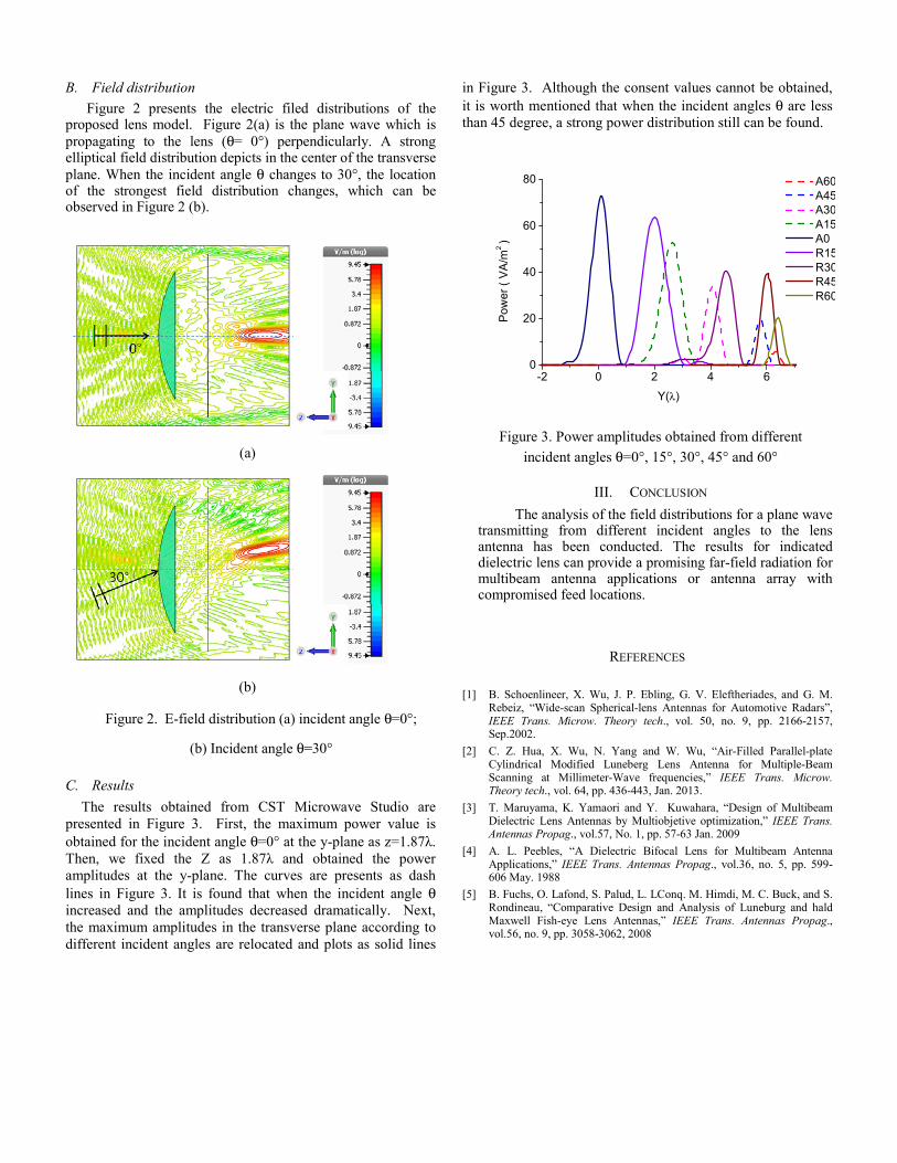
B. Field distribution Figure 2 presents the electric filed distributions of the
proposed lens model. Figure 2(a) is the plane wave which is propagating to the lens (θ= 0°) perpendicularly. A strong elliptical field distribution depicts in the center of the transverse plane. When the incident angle θ changes to 30°, the location of the strongest field distribution changes, which can be observed in Figure 2 (b).
Figure 2. E-field distribution (a) incident angle θ=0°;
(b) Incident angle θ=30°
C. Results The results obtained from CST Microwave Studio are
presented in Figure 3. First, the maximum power value is obtained for the incident angle θ=0° at the y-plane as z=1.87λ. Then, we fixed the Z as 1.87λ and obtained the power amplitudes at the y-plane. The curves are presents as dash lines in Figure 3. It is found that when the incident angle θ increased and the amplitudes decreased dramatically. Next, the maximum amplitudes in the transverse plane according to different incident angles are relocated and plots as solid lines
in Figure 3. Although the consent values cannot be obtained, it is worth mentioned that when the incident angles θ are less than 45 degree, a strong power distribution still can be found.
III. CONCLUSION The analysis of the field distributions for a plane wave
transmitting from different incident angles to the lens antenna has been conducted. The results for indicated dielectric lens can provide a promising far-field radiation for multibeam antenna applications or antenna array with compromised feed locations.
REFERENCES
[1] B. Schoenlineer, X. Wu, J. P. Ebling, G. V. Eleftheriades, and G. M. Rebeiz, “Wide-scan Spherical-lens Antennas for Automotive Radars”, IEEE Trans. Microw. Theory tech., vol. 50, no. 9, pp. 2166-2157, Sep.2002.
[2] C. Z. Hua, X. Wu, N. Yang and W. Wu, “Air-Filled Parallel-plate Cylindrical Modified Luneberg Lens Antenna for Multiple-Beam Scanning at Millimeter-Wave frequencies,” IEEE Trans. Microw. Theory tech., vol. 64, pp. 436-443, Jan. 2013.
[3] T. Maruyama, K. Yamaori and Y. Kuwahara, “Design of Multibeam Dielectric Lens Antennas by Multiobjetive optimization,” IEEE Trans. Antennas Propag., vol.57, No. 1, pp. 57-63 Jan. 2009
[4] A. L. Peebles, “A Dielectric Bifocal Lens for Multibeam Antenna Applications,” IEEE Trans. Antennas Propag., vol.36, no. 5, pp. 599-606 May. 1988
[5] B. Fuchs, O. Lafond, S. Palud, L. LConq. M. Himdi, M. C. Buck, and S. Rondineau, “Comparative Design and Analysis of Luneburg and hald Maxwell Fish-eye Lens Antennas,” IEEE Trans. Antennas Propag., vol.56, no. 9, pp. 3058-3062, 2008
(a)
(b)
-2 0 2 4 60
20
40
60
80 A60A45A30A15 A0R15R30R45R60
Pow
er (
VA
/m2 )
Y(λ)
Figure 3. Power amplitudes obtained from different
incident angles θ=0°, 15°, 30°, 45° and 60°