ELECTROMAGNETIC DRUM BRAKES - Cervis - Industrial...
8
ELECTROMAGNETIC DRUM BRAKES \ `
Transcript of ELECTROMAGNETIC DRUM BRAKES - Cervis - Industrial...

ELECTROMAGNETIC
DRUM BRAKES
\ `
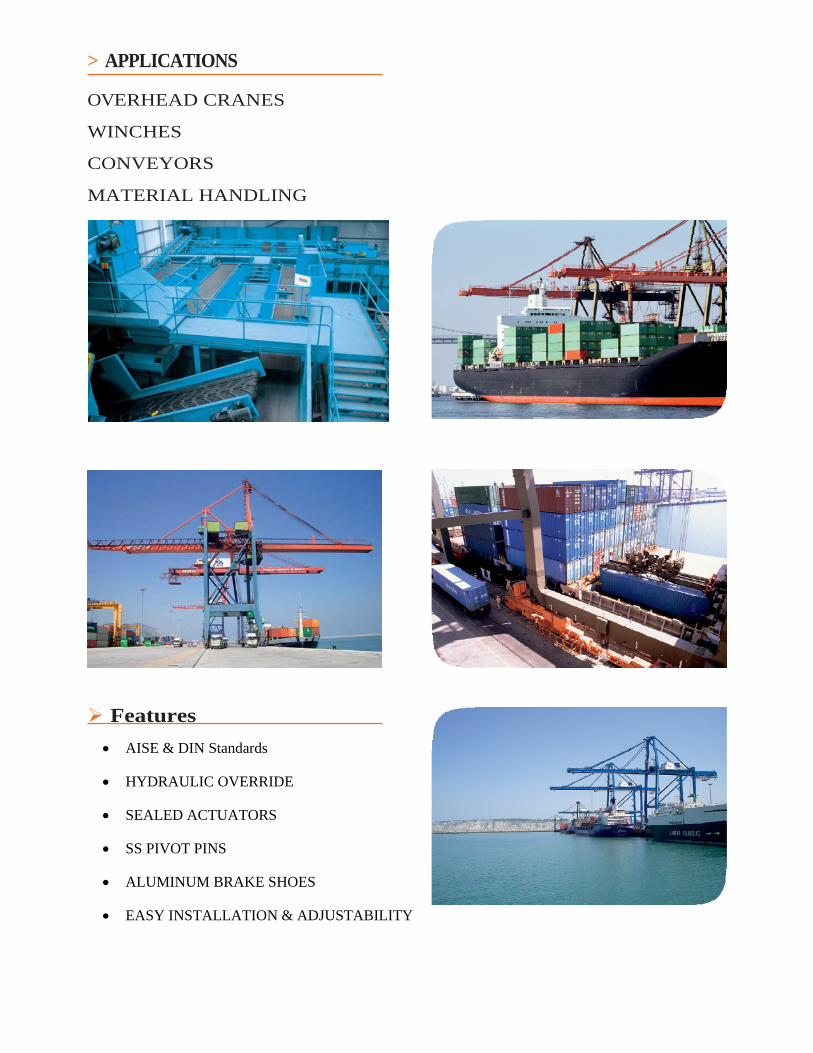
> APPLICATIONS OVERHEAD CRANES
WINCHES
CONVEYORS
MATERIAL HANDLING
Features
AISE & DIN Standards
HYDRAULIC OVERRIDE
SEALED ACTUATORS
SS PIVOT PINS
ALUMINUM BRAKE SHOES
EASY INSTALLATION & ADJUSTABILITY

> General Description
The LAM and LDM brakes are spring applied, electrically released electromagnetic drum brakes. The brake’s release is achieved by DC operated magnets.
There are also combined brakes of the above mentioned and hydraulic override pedal models.
The three major components of a brake set are:
1. The mechanical parts, manufactured in steel. They permit the easy adjustment of the brake torque.
2. The magnet, with housing and armature, made out of laminated steel. Inside the housing is the coil, which is encapsulated in epoxy resin.
3. The braking drum, which can be supplied with a hub or combined with a coupling. It is made of spheroidal graphite iron. Supply can include dynamic balancing and a finishing with machined bores.
These brakes are equipped with stainless steel pins and self lubricating bushes at the pivot points. Brake shoes are manufactured in cast aluminium and linings are asbestos free.
The brakes are supplied according to the following standards:
AISE N.º 11 =LAM brakes and derivated types.
DIN-15.435 = LDM brakes and derivated types.
> Options
1. Automatic lining wear adjustment (RA)
2. Open brake Switch Indicator (CSA)
3. Lining wear Indicator (DD)
4. Hand Release Lever (DM)
5. Special Painting (PE)
> Alternative Models
1. Combined brakes type LAM-EH and LDM-EH (to be consulted).
10 Inch LAM-EH Series
14 Inch LAM Series
1 >
Hydraulic Manual Cylinder
Sealed Actuators

> Operation and control units / Funcionamiento y alimentaciones
Brakes can be connected as follows:
> SHUNT WOUND BRAKES. The magnet coil is shunt connected to the motor.
Different control units can be supplied with the schemes as below.
> Standard voltages: DC: 220 V AC: 220/380 V. 50 Hz. 240/440 V. 60 Hz.
Los frenos se conectan de la siguiente forma:
> CONEXION SHUNT, en la que el bobinado del freno se conecta en paralelo con el motor, a la tensión de la línea.
Las alimentaciones se pueden suministrar según los diferentes esquemas que se indican a continuación:
> Tensiones estándar: CC: 220 V. CA: 220/380 V. 50 Hz. 240/440 V. 60 Hz.
DC Line / Red Corriente Continua
Type AC-1
A resistor is connected in series to the brake in order to decrease the releasing time.
Tipo AC-1
Con resistencia de reducción de corriente para acelerar el tiempo de apertura (se suministra sólo la resistencia).
Type AC-2
By means of a time delayed contactor, the resistor is short-circuited. This is in order to get, even, a better response time when releasing. Current consumption is also decreased.
Tipo AC-2
Con sistema de impulso inicial que por medio de un contactor temporizado cortocircuita la resistencia y de ese modo se mejora aún más la respuesta en la apertura. Además se reduce el consumo.
LINE
LÍNEA
BRAKE FRENO
LINE LÍNEA
BRAKE FRENO
AC Line / Red Corriente Alterna
Type AA-1
With a rectifier to adapt the current of the mains to the DC brake. The rest of the diagram is similar to type AC-l.
When switching-off, the brake current is discharged on the rectifier. This produces a delay when braking.
Tipo AA-1
Con grupo rectificador que adapta la corriente de red a la del freno. El resto es similar al tipo AC-1.
Al cortar la corriente, la energía electromagnética se descarga sobre el rectificador, lo que da lugar a un retardo en el cierre del freno.
Type AA-2
This case is similar to the previous one, but a contactor is included to switch-off the circuit not only before the rectifier, but also between rectifier and brake. This produces a better response time when braking.
Tipo AA-2
Caso similar al anterior, pero la corriente se corta no sólo al rectificador sino también entre éste y el freno. Da lugar a una reducción en el tiempo de cierre del freno.
LINE LÍNEA
Type AA-3
Two contactors are used. This is a combination of types AC-2 and AA-2. Response time is very fast both when braking or releasing.
Tipo AA-3
Con impulso inicial, corte de corriente al rectificador y entre éste y el freno. Su tiempo de respuesta es rápida tanto en la apertura como en el cierre.
LINE LÍNEA
LINE LÍNEA
BRAKE FRENO
BRAKE FRENO
BRAKE FRENO
2 >

> Dimensions and characteristics / Dimensiones y características
BR
AK
E T
YP
E
FR
EN
O T
IPO
Sh
un
t 1
H
Sh
un
t 8
H
Sh
un
t 1
H
Sh
un
t 8
H
PO
WE
R /
C
ON
SU
MO
( W
) 0
º
WE
IGH
T K
g PE
SO
Kg
DR
UM
WID
TH
A
NC
HO
PO
LE
A
SH
OE
WID
TH
A
NC
HO
ZA
PAT
A
> Continuous duty 8 hours. 400 cycles/hour - 100% ED > Intermitent duty 1 hour. 600 cycles/hour - 50% ED > Isolation class F, 155 ºC > Protection class IP-65 > Ambient temperature -20 ºC, +40 ºC
> Servicio 8 horas. 400 maniobras/hora - 100% ED > Servicio 1 hora. 600 maniobras/hora - 50% ED > Aislamiento clase F, 155 °C > Protección clase IP-65 > Temperatura ambiente -20 ºC, +40 ºC
Some models form may vary slightly from the drawing.
Algunos tamaños pueden presentar pequeñas diferencias de forma con el dibujo.
TORQUE Nm.
PAR Nm.
BRAKES TYPE LAM / FRENOS TIPO LAM
According to AISE N.ª 11 - 63.120 / Norma AISE N.ª 11 - 63.120
D I M E N S I O N S / D I M E N S I O N E S
B2 B1 A1 A2 A3 A4 B C D1 D3 F G H H1 H2 I J K
8"
203 140 105 160 120 50 83 77 550 510 185 180 45 235 203 17,5 125 19 178 388 383 146 190 83
10"
254 280 210 200 150 70 95 89 610 580 220 205 45 280 254 17,5 130 19 213 440 435 159 200 102
13"
330 760 550 380 280 135 146 140 775 640 260 235 60 365 330 20,5 180 28 251 623 613 228 280 146
16"
406 1.380 1.040 575 430 205 171 165 890 800 310 295 70 395 406 27 210 34 308 735 730 273 330 190,5
19"
482 2.770 2.080 730 540 230 222 216 1.025 940 365 325 95 440 482 27 240 30 336 808 805 330 390 235
23"
584 5.540 4.150 820 600 365 286 279 1.160 1.150 460 392 107 480 584 33,5 290 20 403 952 947 406 480 298
30"
762 12.450 9.350 980 735 730 362 356 1.465 1.280 510 490 130 550 762 39,5 330 48 527 1.120 1.120 482 560 381
Dimension values are in mm. We reserve the right to modify measures or construction.
Los valores de las cotas están en mm. Nos reservamos toda posibilidad de modificación, de cota o de construcción.
3 >

> Dimensions and characteristics / Dimensiones y características
AK
E T
YP
E
UE
/ P
AR
Nm
.
R /
CO
NS
UM
O
> Continuous duty. 500 cydes/hour - 100% ED > lntermilent duly. 600 cycles/hour - 50% ED > Isolation class F, 155 °C > Protection class IP-65 > Ambient temperature -20 °C, +40 °C
> Servicio continuo 8 horas. 500 maniobras/hora - 100% ED > Servicio intermitente 1 hora. 600 maniobras/hora - 50% ED > Aislamiento clase F, 155 °C > Temperatura ambiente -20 ºC, +40 ºC
Some models form may vary slightly from the drawing.
Algunos tamaños pueden presentar pequeñas diferencias de forma con el dibujo.
I O N Dimension values are in mm. We reserve the right to modify measures or construction.
Los valores de las cotas están en mm. Nos reservamos toda posibilidad de modificación, de cota o de construcción.
4 >

> Dimensions and characteristics / Dimensiones y características
For the control units definition, type, drum diameter, power and service have to be indicated.
Note: There is the possibility of supplying in cabinet.
Para la definición de las alimentaciones, se indicará el tipo de alimentación,tensión de red, diámetro de polea y tipo de servicio.
Nota: Existe la posibilidad de ser suministrado en armario.
Some models form may vary slightly from the drawing.
Algunos tamaños pueden presentar pequeñas diferencias de forma con el dibujo.
CONTROL UNITS FOR ELECTROMAGNETIC DRUM BRAKES 03.639
BRAKE TYPE
LAM LDM
D I M E N S I O N S
C O N T R O L U N I T
AC-2 AA-1 AA-2 AA-3
A B C A B C A B C A B C
8” - 10” 200 - 250 250 145 70 250 35 70 250 90 70 250 145 70
13” - 16” 315 - 400 350 145 70 350 35 70 350 90 70 350 145 70
19” - 23” - 30” 630 - 710 350 145 140 350 35 140 350 90 140 350 145 140
Dimension values are in mm. We reserve the right to modify measures or construction.
5 >

US Sales: Cervis Inc. 170 Thorn Hill Rd Warrendale PA 15086 412‐741‐9000 Phone 412‐741‐9001 Fax www.cervisinc.com [email protected] Aplicación Nuevas Tecnologías Antec, S. A. Ramón y Cajal, 74 48920 Portugalete Vizcaya - Spain Tel.: +34 944 965 011 Fax: +34 944 965 337 [email protected] www.antecsa.com