Electromagnetic compatibility of a low-profile OLED-based ... · Slide 1 Electromagnetic...
15
IMOLA | Midterm Workshop – Ghent – 15.04.2013. | J. Kundrata and A. Baric Slide 1 Electromagnetic compatibility of a low-profile OLED-based lighting device J. Kundrata and A. Baric Midterm Workshop
Transcript of Electromagnetic compatibility of a low-profile OLED-based ... · Slide 1 Electromagnetic...

IMOLA | Midterm Workshop – Ghent – 15.04.2013. | J. Kundrata and A. Baric
Slide 1
Electromagnetic compatibility of
a low-profile OLED-based lighting device
J. Kundrata and A. Baric
Midterm Workshop

IMOLA | Midterm Workshop – Ghent – 15.04.2013. | J. Kundrata and A. Baric
Slide 2
Outline
The electromagnetic compatibility of lighting equipment
Large loop antenna (LLA) measurements
Coupling-decoupling network (CDN) measurements
EMC design challenges
Multi-coil inductor designs:
One-coil (1L) design
Two- (2L) and four-coil (4L) design
Inductor array designs:
Phase and antiphase inductor orientation
Conclusion

IMOLA | Midterm Workshop – Ghent – 15.04.2013. | J. Kundrata and A. Baric
Slide 3
The EMC of lighting equipment (I)
The EMC standard CISPR 15:
“Limits and Methods of Measurement of Radio Disturbance
Characteristics of Electrical Lighting and Similar Equipment”
Radiated disturbance limits in the frequency range 9 kHz to 30 MHz
Radiated disturbance limits in the frequency range 30 MHz to 300 MHz
Large Loop Antenna
measurements
Dipole antenna
measurements
Conducted disturbance limits in the frequency range 30 MHz to 300 MHz
Coupling-decoupling
network measurements
Can be replaced by

IMOLA | Midterm Workshop – Ghent – 15.04.2013. | J. Kundrata and A. Baric
Slide 4
The EMC of lighting equipment (II)
Large Loop Antenna System (three perpendicular loop antennas
D = 2 m)
Defined in CISPR 16 Annex C
f = [300 kHz, 30 MHz]
+

IMOLA | Midterm Workshop – Ghent – 15.04.2013. | J. Kundrata and A. Baric
Slide 5
The EMC of lighting equipment (III)
Coupling-decoupling network (three-port filter that decouples the
conducted RF disturbance from the external power supply and
couples it to the measurement port)
Defined in IEC 61000-4-6
Calibration in CIPSR 15 Annex B
f = [30 MHz, 300 MHz]
+
Teseq

IMOLA | Midterm Workshop – Ghent – 15.04.2013. | J. Kundrata and A. Baric
Slide 6
EMC design challenges (I)
The EM field of a loop antenna
The inductor is basically a loop antenna driven by triangular
waveform currents
The OLED cathode mirrors the antenna currents

IMOLA | Midterm Workshop – Ghent – 15.04.2013. | J. Kundrata and A. Baric
Slide 7
EMC design challenges (II)
The EM field of a matrix of OLED cells:
The radiated disturbance
The relation of neighboring cells phases
The influence of geometrical differences (substrate thickness, cell
spacing etc.)

IMOLA | Midterm Workshop – Ghent – 15.04.2013. | J. Kundrata and A. Baric
Slide 8
Multi-coil inductor designs (I)
Single layer inductor designs
The sub-coils are anti-symmetrically driven
One-coil (1L) design Two-coil (2L) design Four-coil (4L) design

IMOLA | Midterm Workshop – Ghent – 15.04.2013. | J. Kundrata and A. Baric
Slide 9
Multi-coil inductor designs (II)
Equation-based EM-field modelling
1L 2L 4L
Magnetic
field
lin
es
Radia
tion
pattern
Eff,max = -43,5 dbµV/m Eff,max = -105 dbµV/m Eff,max = -172 dbµV/m

IMOLA | Midterm Workshop – Ghent – 15.04.2013. | J. Kundrata and A. Baric
Slide 10
Multi-coil inductor designs (III)
LL-based measurements
1L
4L 2L

IMOLA | Midterm Workshop – Ghent – 15.04.2013. | J. Kundrata and A. Baric
Slide 11
Inductor array designs (I)
A 3 x 3 matrix of 2L inductors modelled by magnetic moments
Equation-based simulations of an inductor array
Randomized phase
Slightly randomized, perturbed location of inductors

IMOLA | Midterm Workshop – Ghent – 15.04.2013. | J. Kundrata and A. Baric
Slide 12
Inductor array designs (II)
Monte Carlo analysis, N = 1000
Randomized current phase and inductor position
IOLED = 240 mA (sine waveform)
IMOLA | Midterm Workshop – Ghent – 15.04.2013. | J. Kundrata and A. Baric
Slide 13
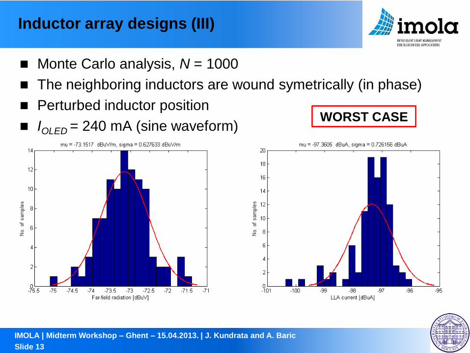
Inductor array designs (III)
Monte Carlo analysis, N = 1000
The neighboring inductors are wound symetrically (in phase)
Perturbed inductor position
IOLED = 240 mA (sine waveform)
WORST CASE

IMOLA | Midterm Workshop – Ghent – 15.04.2013. | J. Kundrata and A. Baric
Slide 14
Inductor array designs (IV)
Monte Carlo analysis, N = 1000
The neighboring inductors are wound antisymetrically
(in antiphase)
Perturbed inductor position
IOLED = 240 mA (sine waveform)
BEST CASE

IMOLA | Midterm Workshop – Ghent – 15.04.2013. | J. Kundrata and A. Baric
Slide 15
Conclusion
The CISPR 15 sets the limits on the radiated and the
conducted disturbance of the lighting equipment
The Large Loop Antenna and the Coupling-decoupling
network measurements cover the entirety of OLED module
EMC tests
The multi-coil inductor designs are more EMC-friendly than the
single-coil inductor designs
An OLED matrix with neighboring tiles inductors wound
antisymetrically has the best performance w.r.t. EMC