Electromagnetic characteristics of filaments for 3D ...
6
Electromagnetic characteristics of filaments for 3D printing with carbon fillers in the microwave range Grigoriy E. Kuleshov 1,* , Alexander V. Badin 1 , Kirill V. Bilinsky 1 , and Kirill V. Dorozhkin 1 1 National Research Tomsk State University, 634050, Tomsk, Russia Abstract. The results of a study of the complex permittivity and electromagnetic response from polymer composite materials obtained by additive technology from 3D printing filaments containing various carbon fillers are presented. New radio filaments for 3D printing with MWCNTs have been created. Investigated PLA-Conductive plastics may be used to create a shielding coating or narrowband absorbers for microwave range. 1 Introduction Over the past decades, components and devices obtained by additive technologies have begun to be actively applied and implemented [1-4]. Additive technologies have a number of advantages compared to standard ones: fewer operations, waste-free use of initial components, ease of development and optimization of products in CAD engineering programs, and high technology [5-7]. Recently, the manufacture of composite materials based on plastics for 3D printing with the addition of fillers effectively interacting with electromagnetic radiation is developing more and more actively [8-10]. Over the past 5 years, the number of works devoted to the development and research of such radiomaterials has grown more than ten times. The use of additive technology with radiofilaments allows you to create completely new elements and compositional structures, and also makes it possible to significantly speed up and reduce the cost of the production of protective coatings and radio components for microwave devices. This theme is extremely important and has great prospects for practical use. Among filaments for 3D printing, conductive plastics stand out. As a rule, they contain various carbon structures (carbon fibers, nanotubes, graphene) in their composition [11-13]. For their use as radio materials, it is necessary to know the exact information about the values of their complex permittivity and conductivity. This paper presents the results of a study of microwave electromagnetic characteristics of industrially produced and self-made filaments for 3D printing containing various carbon fillers. 2 Objects of research The objects of study are composite radio materials manufactured using additive technology (3D printing) from industrially produced and self-made plastic filaments containing various * Corresponding author: [email protected] , 0 (2019) https://doi.org/10.1051/itmconf /201930 ITM Web of Conferences 30 CriMiCo'2019 0 70 70 10 10 © The Authors, published by EDP Sciences. This is an open access article distributed under the terms of the Creative Commons Attribution License 4.0 (http://creativecommons.org/licenses/by/4.0/).
Transcript of Electromagnetic characteristics of filaments for 3D ...

Electromagnetic characteristics of filaments for 3D printing with carbon fillers in the microwave range
Grigoriy E. Kuleshov1,*, Alexander V. Badin1, Kirill V. Bilinsky1, and Kirill V. Dorozhkin1
1National Research Tomsk State University, 634050, Tomsk, Russia
Abstract. The results of a study of the complex permittivity and
electromagnetic response from polymer composite materials obtained by
additive technology from 3D printing filaments containing various carbon
fillers are presented. New radio filaments for 3D printing with MWCNTs
have been created. Investigated PLA-Conductive plastics may be used to
create a shielding coating or narrowband absorbers for microwave range.
1 Introduction
Over the past decades, components and devices obtained by additive technologies have begun
to be actively applied and implemented [1-4]. Additive technologies have a number of
advantages compared to standard ones: fewer operations, waste-free use of initial components,
ease of development and optimization of products in CAD engineering programs, and high
technology [5-7]. Recently, the manufacture of composite materials based on plastics for 3D
printing with the addition of fillers effectively interacting with electromagnetic radiation is
developing more and more actively [8-10]. Over the past 5 years, the number of works devoted
to the development and research of such radiomaterials has grown more than ten times. The use
of additive technology with radiofilaments allows you to create completely new elements and
compositional structures, and also makes it possible to significantly speed up and reduce the
cost of the production of protective coatings and radio components for microwave devices.
This theme is extremely important and has great prospects for practical use.
Among filaments for 3D printing, conductive plastics stand out. As a rule, they contain
various carbon structures (carbon fibers, nanotubes, graphene) in their composition [11-13].
For their use as radio materials, it is necessary to know the exact information about the
values of their complex permittivity and conductivity.
This paper presents the results of a study of microwave electromagnetic characteristics of
industrially produced and self-made filaments for 3D printing containing various carbon fillers.
2 Objects of research
The objects of study are composite radio materials manufactured using additive technology
(3D printing) from industrially produced and self-made plastic filaments containing various
* Corresponding author: [email protected]
, 0 (2019) https://doi.org/10.1051/itmconf /201930ITM Web of Conferences 30CriMiCo'2019
070 7010 10
© The Authors, published by EDP Sciences. This is an open access article distributed under the terms of the CreativeCommons Attribution License 4.0 (http://creativecommons.org/licenses/by/4.0/).

carbon fillers. As filaments for 3D printing were used: 1) Proto-pasta PLA-Conductive
“ProtoPlant Inc.” (USA), with conductive carbon: resistivity 102-103 Ohm/cm; 2) ABS-
Conductive filament “Mellow” (China) containing carbon fibers: resistivity 104-105
Ohm/cm; 3) Self made filaments: ABS + MWCNT with an average diameter of 9.4 nm in
concentrations up to 5 wt.%. When making the radiofilament independently, the following scheme was used (Fig. 1). At
the first stage, ABS plastic was crushed and dissolved in acetone, and then MWCNTs were added. Next, the resulting mixture was thoroughly mixed and subjected to ultrasonic dispersion for 10 minutes at a power of 75 watts. After complete polymerization, the resulting material was crushed and hot extruded to create a filament. At the final stage, using the obtained radiofilament, a sample in the form of a washer with a thickness of h = 2.25 mm with an inner diameter of d = 3 mm and an external D = 7 mm were printed on a 3D printer.
Fig. 1. The process of manufacturing samples based on ABS plastic and MWCNTs.
3 Measurement technique and experimental results
The electromagnetic characteristics of the composites were studied using the waveguide method in a coaxial measuring cell on the vector circuits analyzer P4M-18 manufactured by “Mikran” in the frequency range from 0.1 to 18.00 GHz. In this case, to the “to pass” measurement schemes were used (Fig. 2). It allows you to measure S-parameters and their phase. Based on the obtained data by the Becker-Jarvis method [14], spectra of complex permittivity of the material were calculated.
Then, from the obtained data on the complex permittivity, with the virtual absence of magnetic properties, we simulated the electromagnetic response from a layer of material located in free space (transmission coefficient) and on the metal (reflection coefficient). For the respective coefficients, distribution plots depending on the thickness and frequency of the layer were obtained.
Fig. 2. Appearance and block diagram of the experimental setup.
, 0 (2019) https://doi.org/10.1051/itmconf /201930ITM Web of Conferences 30CriMiCo'2019
070 7010 10
2

4 Results and discussion
As a result of measurements and calculations, the spectra of the complex permittivity of composites based on carbon-containing filaments for 3D printing were obtained. The frequency dependences of the real part of the complex permittivity are shown in Fig. 3.
Fig. 3. Frequency dependence of the real part of the complex permittivity for a composite samples based on carbon-containing filaments.
The graphs show that largest values of the real part of the complex dielectric constant have samples of materials based on PLA-Condactive plastic (13-8 rel. units) and ABS-Condactive plastic (8.5-7.5 rel. units). Moreover, at lower frequencies they have higher values of ε ', which decrease with increasing frequency, due to the presence of conductive properties in the materials. Samples based on ABS plastic with the addition of MWCNTs take ε' values within 3.5–7 rel. units. With an increase in the concentration of MWCNTs, ε' also increases. For these samples, with increasing frequency ε' practically does not change.
Next, Fig. 4 shows the frequency dependences of the imaginary part of the complex permittivity.
Fig. 4. Frequency dependence of the imaginary part of the complex permittivity for a composite based on carbon-containing filaments.
, 0 (2019) https://doi.org/10.1051/itmconf /201930ITM Web of Conferences 30CriMiCo'2019
070 7010 10
3
It follows from the graphs that the largest values of the imaginary part of the complex
permittivity have samples of materials based on PLA-Condactive plastic (3.8-3 rel. units)
and ABS-Condactive plastic (2.3-1 rel. units). And samples based on ABS plastic with the
addition of MWCNTs take ε'' values not exceeding 0.75 rel. units. With an increase in the
concentration of MWCNTs, ε'' also increases. It should be noted that with an increase in the
frequency ε'' in conductive plastics decreases. This is due to the contribution of losses to the
conductivity in the imaginary part of the complex permittivity.
The following are the results of modeling the electromagnetic response. For modeling,
as an example, the sample with the highest values of dielectric constant was selected.
Namely, coatings based on PLA-Condactive plastic placed in free space and coatings
deposited on metal.
In free space, the shielding ability of the material was calculated, i.e. spectra of
transmission coefficient depending on the thickness of the coating (Fig.5).
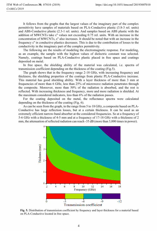
The graph shows that in the frequency range 2-18 GHz, with increasing frequency and
thickness, the shielding properties of the coatings from plastic PLA-Conductive increase.
This material has good shielding ability. With a layer thickness of more than 3 mm at
frequencies of more than 6 GHz, less than 25% of microwave radiation penetrates through
the composite. Moreover, more than 50% of the radiation is absorbed, and the rest is
reflected. With increasing thickness and frequency, more and more radiation is shielded. At
the maximum considered indicators, less than 6% of the radiation passes.
For the coating deposited on the metal, the reflectance spectra were calculated
depending on the thickness of the coating (Fig. 6).
As can be seen from the graph, in the range from 5 to 18 GHz, a composite based on PLA-
Conductive has large reflection losses, but at a certain thickness. It can be used as an
extremely efficient narrow-band absorber at the considered frequencies. So at a frequency of
5-6 GHz with a thickness of 4-5 mm and at a frequency of 17-18 GHz with a thickness of 2
mm, the attenuation of reflected radiation can reach -35 dB (more than 3,000 times in power).
Fig. 5. Distribution of transmission coefficient by frequency and layer thickness for a material based
on PLA-Conductive located in free space.
, 0 (2019) https://doi.org/10.1051/itmconf /201930ITM Web of Conferences 30CriMiCo'2019
070 7010 10
4

Fig. 6. Distribution of reflection coefficient by frequency and layer thickness for a material based on
PLA-Conductive located on a metal.
The research was supported by The Tomsk State University competitiveness improvement
programme.
References
1. S. Koziel, J. Meng, J. W. Bandler, J. W. Bakr, Q. S. Cheng, IEEE Trans. on MW. Theor. and Tech., 57, 383 (2009)
2. V. Laur, M. Kaissar Abboud, A. Maalouf, D. Palessonga, A. Chevalier, J. Ville,
APMC, 1318 (2019)
3. P. Pa, Z. Larimore, P. Parsons, M. Mirotznik, Elect. Lett., 51, 1561 (2015)
4. S. Johann, F. William, P. Aurélien, T. Olivier, D. Nicolas, S. Bila, V. Serge, P. Jean-
Baptiste, R. Gramond, EuMC 2016, 373 (2016)
5. E. Drahi, A. Gupta, S. Blayac, S. Saunier, P. Benaben, Phys. St. Sol. (A) App. and
Mat. Sci., 211, 1301 (2014)
6. M. D'Auria, W. J. Otter, J. Hazell, B. T. W. Gillatt, C. Long-Collins, N. M. Ridler,
S. Lucyszyn, IEEE Trans. on Comp., Pack. and Manuf. Tech., 5, 1339 (2015)
7. J. G. Hester, S. Kim, J. Bito, T. Le, J. Kimionis, D. Revier, C. Saintsing, W. Su,
B. Tehrani, A. Traille, B.S. Cook, M. M. Tentzeris, Proc. of the IEEE, 103, 583 (2015)
8. Y. Wang, F. Castles, P. S. Grant, Mat. Res. Soc. Sym. Proc, 1788, 29 (2015)
9. M. RaviPrakash, S. Anuj, K. Balasubramanian, Mat. Lett., 238, 214 (2019)
10. S. Mishra, P. Katti, S. Kumar, S. Bose, Chem. Eng. J., 357, 384 (2019)
11. A. V. Badin, G. E. Kuleshov, K. V. Dorozhkin, G. E. Dunaevskii, V. I. Suslyaev,
V. A. Zhuravlev, IRMMW-THz, 8509938 (2018)
, 0 (2019) https://doi.org/10.1051/itmconf /201930ITM Web of Conferences 30CriMiCo'2019
070 7010 10
5

12. Z. Hu, F. Chen, J. Xu, Q. Nian, D. Lin, C. Chen, M. Zhang, J. of Al. and Comp., 746,
269 (2018)
13. M. Hasan, J. Saa'diAbdul, A. H. Mohammed, A. H. Yazan, W. Salah, Phys.B: Cond.
Matt., 418, 41 (2013)
14. K. Chalapat, K. Sarvala, J. Li, G.S. Paraoanu, IEEE Trans. on MW. Theor. and Tech.,
57, 2257 (2009)
, 0 (2019) https://doi.org/10.1051/itmconf /201930ITM Web of Conferences 30CriMiCo'2019
070 7010 10
6