ELECTROMACH member of the R.STAHL Technology … · operating instructions control box cbe...
21
OPERATING INSTRUCTIONS CONTROL BOX CBE DISTRIBUTION BOX CBE SWITCH/DISTRIBUTIONS PANELS CBE ELECTROMACH member of the R.STAHL Technology Group ELECTROMACH B.V. Jan Tinbergenstraat 193 7559 SP Hengelo The Netherlands T +31 (0)74 2 472 472 F +31 (0)74 2 435 925 [email protected] www.electromach.com Bank: ABN-AMRO 59.01.14.573 IBAN: NL29ABNA0590114573 BIC: ABNANL2A VAT/BTW: NL 003578458B01 Bank: Fortis 24.35.24.439 IBAN: NL67FTSB0243524439 BIC: FTSBNL2RXXX KVK nr: 06040491 Leveringen geschieden overeenkomstig de voorwaarden. Deliveries subject to general conditions of sale.
Transcript of ELECTROMACH member of the R.STAHL Technology … · operating instructions control box cbe...
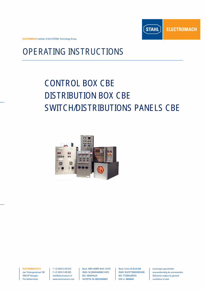
OPERATING INSTRUCTIONS
CONTROL BOX CBEDISTRIBUTION BOX CBESWITCH/DISTRIBUTIONS PANELS CBE
ElEctromach member of the R.STAHL Technology Group
ElEctromach B.V.Jan Tinbergenstraat 1937559 SP HengeloThe Netherlands
T +31 (0)74 2 472 472F +31 (0)74 2 435 [email protected]
Bank: ABN-AMRO 59.01.14.573IBAN: NL29ABNA0590114573BIC: ABNANL2AVAT/BTW: NL 003578458B01
Bank: Fortis 24.35.24.439IBAN: NL67FTSB0243524439BIC: FTSBNL2RXXXKVK nr: 06040491
Leveringen geschieden overeenkomstig de voorwaarden. Deliveries subject to general conditions of sale.

PAGE 2/ 21
INDEXAPPLICATION.................................................................................................................................................... 3PURPOSE OF THESE INSTRUCTIONS .......................................................................................................... 31 SAFETY INSTRUCTIONS .............................................................................................................................. 4
1.1 CONFORMITY TO STANDARDS ........................................................................................................... 4
2 TECHNICAL DATA ......................................................................................................................................... 63 MOUNTING ..................................................................................................................................................... 7
3.1 MECHANICAL INFORMATION ............................................................................................................... 7
4 INSTALLATION .............................................................................................................................................. 94.1 BACK-UP FUSE ....................................................................................................................................... 94.2 INTERNAL WIRING ................................................................................................................................. 9
4.2.1 CABLES ............................................................................................................................................ 94.2.2 CABLE RUNNING ............................................................................................................................ 94.2.3 INTRINSICALLY SAFE CIRCUITS ................................................................................................. 94.2.4 TERMINAL BLOCKS ..................................................................................................................... 104.2.5 EXTERNAL-CABLING ................................................................................................................... 114.2.6 EARTHING-CONDUCTOR ............................................................................................................ 11
5 COMMISSIONING ......................................................................................................................................... 136 REPAIRS AND MAINTENANCE ................................................................................................................. 147 ACCESSORIES / SPARE ............................................................................................................................. 178 DISPOSAL ..................................................................................................................................................... 179 EC-TYPE EXAMINATION CERTIFICATE ................................................................................................... 1810 DECLARATION OF CONFORMITY .......................................................................................................... 21

PAGE 3/ 21
APPLICATIONType CBE control and distribution boxes and switch and distribution panels are used, together with theequipment fitted in them, to control, switch and conduct electrical energy. These enclosures are intendedfor local mounting as standard.
PURPOSE OF THESE INSTRUCTIONSWorking in hazardous areas, the safety of personnel and plant depends on complying with all relevantsafety regulations.
Assembly and maintenance staff working on installations therefore have a particular responsibility. Theyrequire precise knowledge of the applicable standards and regulations.
These instructions give a brief summary of the most important safety measures. They supplement thecorresponding regulations which the staff responsible must study.

PAGE 4/ 21
1 SAFETY INSTRUCTIONSUse the enclosures only for their intended purpose.
Incorrect or impermissible use or non-compliance with these instructions invalidates our warrantyprovision.
No changes to the enclosures impairing their explosion protection are permitted.
Mount the enclosures only if they are clean and undamaged.
Observe the following when using the enclosures:national safety regulations;national accident prevention regulations;national installation regulations;(e.g. IEC 60079-14)generally recognized technical regulations;safety guidelines in these operating instructions;characteristic values, rated operating conditions, temperature class and explosion protection onthe rating and data plates;additional instruction plates on the enclosures.
Combined switch panels may only be operated with enclosures fully closed.Any damage can invalidate the Ex-protection.
If required, we will provide a copy of the EC Type-Test Certificate with the relevant annex.
1.1 CONFORMITY TO STANDARDSThe enclosures comply with the following standards and regulations:Directive 94/9/ECEN 50014, EN 50017, EN 50018,EN 50019, EN 50020, EN 50028,EN 50281-1-1

PAGE 5/ 21
Equivalent international standards:IEC 60079-0 (1998)IEC 60079-1 (2001)IEC 60079-2 (2001)IEC 60079-5 (1997)IEC 60079-7 (1990)IEC 60079-11 (1991)IEC 60079-18 (1992)IEC 61241-1 ( )
EN 60947-1EN 60439-1
Type CBE enclosures are suitable for use in hazardous areas, zones 1, 2, 21 and 22.

PAGE 6/ 21
2 TECHNICAL DATAExplosion protection II 2GD EEx e. II. T.Test certificate KEMA 02 ATEX 2273Material Sheet steel (galvanized and painted) or stainless
sheet steelDegree of protection to IEC/CEI 60529 max. IP 66 (dependent on fittings)
The devices fitted to type CBE enclosures differ according to customers’ requirements.Please also observe the operating instructions for these.
The devices fitted determine the electrical data. Please observe the values on their typeand rating plates.
Working temperature range - 20 C ... + 55 C
If the ambient temperature < - 20 oC, then either special „low temperature“ cable glandsmust be used or the enclosure must be so mounted that the cable glands are mechanicallyprotected.
Rated operating voltage max. 11 kVConnection cross-section max. 300 mm²Rated current max. 1250 A
Please consult the manufacturer if operating conditions are non-standard.

PAGE 7/ 21
3 MOUNTING3.1 MECHANICAL INFORMATIONMechanical details relating to fixing point positions, tolerances or weight of combined switch panels can beobtained from the construction drawing enclosed.
When explosion-protected electrical equipment is exposed to the weather, it is advisable to provide aprotective cover or wall.
To avoid condensation forming in the metal enclosure, we recommend using a breather. Itshould be noted however, that this can result in a reduction in the degree of protection toIEC 60529, depending on where the breather is mounted.
Transport and storage is only permitted in the original packaging.

PAGE 8/ 21
1) WELDSTUDS M8x15 ON REARSIDE CAN BE USED FOR FRAMEMOUNTING
To securely fix the enclosures marked with *), use either the lugs supplied or the tapped holes in theenclosure base.

PAGE 9/ 21
4 INSTALLATIONTo avoid moisture and dirt collecting inside the combined switch panels, electricalinstallation must be carried out in a clean and dry environment. The enclosures may onlybe opened to carry out installation work and must be carefully closed again followingcompletion of the work.
4.1 BACK-UP FUSEThe system must be protected by the back-up fuse specified. The fuse rating must be such that it blowswhen an appropriate system short-circuit current occurs.
4.2 INTERNAL WIRING4.2.1 CABLESCables of the following types only may be used for internal wiring of the control or distribution panels:
H 05 V 2 for T6)H 07 G for T5) - or equivalent.
Minimum cross-section 1.5 mm2 copper.
4.2.2 CABLE RUNNINGThe cables must be run such that the leakage and air distances necessary for EEx “e“ are maintained.
To facilitate orderly cable connection, the mounting rails and components may be loosened. They musthowever be fully tightened again when connections have been made.
4.2.3 INTRINSICALLY SAFE CIRCUITSOnly insulated cables whose test voltage is at least AC 500 V and whose quality is at least H05 may beused for intrinsically safe circuits.
The diameter of individual conductors may not be less than 0.1 mm. This also applies to the individualwires of multi-strand cables.

PAGE 10/ 21
With regard to the insulation and separation of terminals and cables, it should be noted that the insulationtest voltage is derived from the sum of the rated operating voltages of intrinsically safe and non-intrinsicallysafe circuits.
In the case of „intrinsically safe against earth“ then the insulation voltage value is at least 500 V (or doublethe value of the intrinsically safe circuit rated operating voltage).
In the case of „intrinsically safe against non-intrinsically safe“, then the insulation voltage value is at least1500 V (or double the rated operating voltage plus 1000 V).
Cables for EEx „i “ circuits must be run at least 8 mm away from the cables of other intrinsically safecircuits.
The only exception to this is the use of cables in which the cores of the intrinsically safe or the non-intrinsically safe circuit are surrounded by an earthed screen.
The pre-conditions for the separation between parts to be connected for intrinsically safe and non-intrinsically safe circuits are:
a distance of 50 mm around an insulating (> 1 mm thick) or earthed metal (> 0.45 mm thick)isolating plateoran isolating plate which is separated from enclosure walls by a distance< 1.5 mm.
4.2.4 TERMINAL BLOCKSOnly 1 cable may be connected per individual terminal. Links may only be made using original Ex-accessories.
Any isolating plates necessary may be fitted later.
Please take note of the terminal test certificate!
If additional protection against cable end splaying is necessary, then end-sleeves or lugs must be used. Ifend-sleeves are used, it is vital that these are gas-tight and fitted with the correct tool.
PAGE 11/ 21
The cross-section of such additional devices used must match that of the cable.
4.2.5 EXTERNAL-CABLINGConnecting cables must be led through the cable glands into the connection chamber complete with theirexternal insulation. This means that care must be taken to ensure that the external diameter of the cablematches the clamping cross-section specified for the cable gland.
To ensure that the connection chamber is fully sealed and all connections protected from strain, thehexagonal nuts of the cable glands must be fully tightened.
The cables must be run in the connection chamber such that the minimum permissible bending radius foreach cross-section is not exceeded and mechanical damage to cable insulation from sharp edges ormoving metal parts is avoided.
Please observe the following points:Connections must be made with special care;The conductor insulation must reach to the terminal. The conductor itself must not be damaged(nicked) when removing the insulation;Ensure that the maximum permissible conductor temperatures are not exceeded by suitableselection of cables and means of running them (avoid bunched cables);The permissible ambient temperature of the intrinsically safe equipment and devices fitted mustnot be exceeded.
4.2.6 EARTHING-CONDUCTORAn earth connection must be made in all circumstances.
All blank, non-live metal parts must be included in the earthing system, whatever the operating voltagevalue.
Neutral conductors are considered to be live conductors in this area and must be run accordingly, i.e.insulation, cover, EEx „e“ certified terminals etc.
Inactive metal parts are insulated to EN 60439 (Part 1) and not connected to earth.

PAGE 12/ 21
Please take the details relating to potential equalization, earthing and intrinsically safecircuits from the documentation of the relevant equipment.
The external earth conductor connection accepts a cable lug. The cable must be run close to theenclosure to avoid it loosening.
When all electrical installation work is complete, carry out the following:Fix touch guards;Adjust set values of tripping devices;Make visual checks for presence of loose metal parts, dirt and moisture;If necessary, clean and dry the connection chamber.
Please take note of the accompanying documents, such as wiring diagrams and similar.

PAGE 13/ 21
5 COMMISSIONINGPlease convince yourself before operation that the enclosure is completely without damage.
Before commissioning the enclosure, ensure that
it has been correctly installed;it is not damaged;it contains no foreign bodies;the connection area is clean;connections have been correctly made;the cables have been correctly brought in;all screws and nuts are fully tightened;the cable glands are securely tightened;unused cable entries are sealed with plugs certified to Directive 94/9/EC, and unused holes aresealed by stopping plugs certified to Directive 94/9/EC;all covers and isolating plates for live parts are in position and fixed.
If the fixings of the equipment fitted referred to above are over-tightened, the degree of protection can beimpaired.
We recommend the use of type 8290 stopping plugs for unused holes in the enclosure andtype 8161 plugs for unused cable entries. Both are available from R.STAHL SchaltgeräteGmbH.
Any enclosure wired by the customer must be insulation tested to EN 60439-1.
PAGE 14/ 21
6 REPAIRS AND MAINTENANCEDo not open enclosure when supply is switched on!Do not open when non-intrinsically safe circuits are energized!Exception: Enclosures with intrinsically safe and non-intrinsically safe circuits with thenotice „Non-intrinsically safe circuits protected by IP 30 cover“ may be opened whensupplied with power.
Repairs and maintenance work on the enclosures may only be carried out by appropriately authorized andtrained personnel.
Observe the relevant national regulations for your country!
If any flameproof devices fitted are damaged, absolutely no repair or maintenance workmay be undertaken on them. Please replace any such device in this case.
For the purposes of maintenance work, the length of time between periodic checks shall be so set that anysystem faults likely to arise are found promptly. The maximum interval between checks is three years.
Note the following when establishing the interval between checks:the ambient conditions (installed in the open, wind, rain, sunlight, etc);the operating conditions (utilization of system, operator errors);manufacturers‘ instructions in technical documentation (mechanical and electrical life ofswitchgear);big changes in the whole system (e.g. change of zone allocation).
Checks should be by sight, adjacent or detailed, depending on local conditions.If faults are found during these checks which affect the explosion protection, then the system must betaken out of service until the faults have been cleared.

PAGE 15/ 21
The following points must be checked during maintenance:clamping screw holding the cable is securely seated;compliance with permitted temperatures (to EN 50014);damage to the gaskets;damage to the cable glands;state of potential equalization conductor external connection.
Please ensure that when maintaining several enclosures, the covers and enclosures arenot mixed up. When maintenance is complete, the covers must be carefully closed.
Checking the enclosures externally:The enclosures must show no external damage such as cracks, holes, dents, material brittlenessor corrosion.
Checking the flameproof joints (fitted equipment):All flameproof joints (flat, cylindrical, threaded) must be seen to be perfect. There must be novisible evidence of corrosion;The thread of threaded joints must not be damaged. At least five perfect turns of thread must beengaged;Flat joints must also show no damage;The average roughness of the joint surfaces must not exceed 6.3 um in peak-to-valley height.3
In case of doubt, these - and other values relating to flameproof joints - can be checked andcompared with the standard values in EN 50018.Rusted joints must not be cleaned with abrasives or wire brushes, but only by chemicalmeans, e.g. non-oxidizing oils such as ESSO, VARSOL or others.
To prevent attack by corrosion, the flameproof joints of metal enclosures must be regularly treated with anacid-free grease, e.g. OKS sea-water resistant.

PAGE 16/ 21
Corrosion-protection by painting is forbidden in principle.
Checking cable glands and pipe entries:The tightness of all screw joints and the condition of the seal around each one must be checked;Where there are direct entries into the pressurized area, check that the explosion protection issecure at the transition from screw joint seal to cable outer surface insulation.
Checking the condition of inspection glasses:The condition of inspection glasses must be carefully examined. In particular, care must be takento ensure that there are no scratches on the surface likely to reduce the glass breaking strength.
Clean inspection glasses with a damp cloth.
Checking the internal condition of combined switch panels:The inside of the enclosures must be checked regularly. Such a check must include examining thecondition of the sealing system as well as the internal surfaces.The general visual check should include establishing whether condensation or dirt havepenetrated the inside. Both can lead to the formation of leakage paths to insulating materialsurfaces and thus cause short-circuits or impermissible warming within the enclosure. If dirt orcondensation is found inside the pressurized area, it must be carefully removed.If enclosure gaskets show signs of damage, they must be changed immediately.The insulation must be checked for damage and leakage paths.The mechanical fixing of equipment fitted and the condition of electrical contacts must beexamined. In particular, a check should be made for signs of impermissible warming and ofcontact stability.On completion of checking and maintenance, the enclosures must be properly closed.

PAGE 17/ 21
Checking the condition of the equipment fitted:This check ensures that the lifetime (mechanical and electrical) specified by the manufacturer isnot exceeded.If short-circuits occur in the system, the equipment and components included in the affected circuitmust be changed, if it is not possible to examine the internal condition of the contact system.
7 ACCESSORIES / SPAREWhen terminal blocks are fitted, care must be taken to ensure that they are of the type permitted byDirective 94/9/EC.
Use only original accessories and spare parts.
8 DISPOSALObserve the national standards for refuse disposal.
We are pleased to answer any special questions you may have.
Should you require the operating instructions in one of the other European Community languages, pleasefeel free to contact Electromach.

PAGE 18/ 21
9 EC-TYPE EXAMINATION CERTIFICATE

PAGE 19/ 21

PAGE 20/ 21

PAGE 21/ 21
10 DECLARATION OF CONFORMITY