electrokinetic phenomena in colloidal clays abstract introduction
15
ELECTROKINETIC PHENOMENA IN COLLOIDAL CLAYS By D. T. OAKES 1 AND EMIL J. BURCIK The Pennsylvania State University, University Park, Pennsylvania ABSTRACT While the variations of the physical properties of colloidal suspensions of bentonite days under various conditions of contamination have been the subject of extensive investigations, the role of the associated electrical phenomena in the impartation of these physical properties is virtually undefined. Successful techniques for the measurement of the electrical phe- nomena have been reported previously but they are applicable only to very dilute clay sus- pensions in which negligible electrical interference between clay particles exists. Apparatus and techniques applicable to concentrations of colloidal material normally used in bentonite oil-well drilling fluids were developed and are discussed. Measurement of electrokinetic phenomena in concentrated suspensions was effected by application of the principle of electroosmosis by suitable modification of existing apparatus. The distinguishing modification was replacement of the conventional, consolidated di- aphragm with a diaphragm of colloidal material supported by thin membranes. The applicability of the apparatus and techniques is demonstrated by qualitative compari- son with data of previous investigations wherein the comparable depression of the electro- kinetic potential by the addition of various contaminating ions is shown. In addition, the relation between the measured electrokinetic potential and the filtration rate is shown to be linear and independent of the valence or type of contaminant for a major portion of the investigated concentration range. This suggests that for ions which appreciably repress the electrokinetie potential the fluid-loss may be used as a means of approximating the changes of the electrokinetic potential. INTRODUCTION Colloidal dispersions of bentonite clays impart to the drilling fluid the desir- able properties of viscosity, thixotropy and low fluid-loss. Under certain cir- cumstances of contamination, however, the colloidal character of bentonite par- ticles may be so adversely affected that they impart undesirable characteristics to the drilling fluid. Detailed studies of these circumstances of contamination have been made by numerous investigators and data are available relating the viscosity, thixotropy and fluid-loss of various types of bentonite with the concentration of the contam- inating materials. However, extremely meager information is available on the more fundamental relationships between the electrical and physical properties of the colloidal clay particles. Likewise, practically no data relating the electric- al properties of clays with the surrounding atmosphere of various ions are found in the literature. As the characteristics of viscosity, thixotropy and fluid-loss are considered to be to a large extent physical manifestations of the electrical properties of the col- loidal clay particles, it is believed that refinement of drilling-fluid treatment techniques may be supplemented materially by studies of the electrical phenom- ena involved. Present address, Research Department, Lion Oil Company, E1 Dorado, Arkansas. 225
Transcript of electrokinetic phenomena in colloidal clays abstract introduction
ELECTROKINETIC PHENOMENA IN COLLOIDAL CLAYS
By D. T. OAKES 1 AND EMIL J. BURCIK
The Pennsylvania State University, University Park, Pennsylvania
ABSTRACT
While the variations of the physical properties of colloidal suspensions of bentonite days under various conditions of contamination have been the subject of extensive investigations, the role of the associated electrical phenomena in the impartation of these physical properties is virtually undefined. Successful techniques for the measurement of the electrical phe- nomena have been reported previously but they are applicable only to very dilute clay sus- pensions in which negligible electrical interference between clay particles exists. Apparatus and techniques applicable to concentrations of colloidal material normally used in bentonite oil-well drilling fluids were developed and are discussed.
Measurement of electrokinetic phenomena in concentrated suspensions was effected by application of the principle of electroosmosis by suitable modification of existing apparatus. The distinguishing modification was replacement of the conventional, consolidated di- aphragm with a diaphragm of colloidal material supported by thin membranes.
The applicability of the apparatus and techniques is demonstrated by qualitative compari- son with data of previous investigations wherein the comparable depression of the electro- kinetic potential by the addition of various contaminating ions is shown. In addition, the relation between the measured electrokinetic potential and the filtration rate is shown to be linear and independent of the valence or type of contaminant for a major portion of the investigated concentration range. This suggests that for ions which appreciably repress the electrokinetie potential the fluid-loss may be used as a means of approximating the changes of the electrokinetic potential.
INTRODUCTION
Colloidal dispersions of bentonite clays impart to the drill ing fluid the desir- able properties of viscosity, thixotropy and low fluid-loss. Under certain cir- cumstances of contamination, however, the colloidal character of bentonite par- ticles may be so adversely affected that they impart undesirable characteristics to the drilling fluid.
Detailed studies of these circumstances of contamination have been made by numerous investigators and data are available relating the viscosity, thixotropy and fluid-loss of various types of bentonite with the concentration of the contam- inating materials. However, extremely meager information is available on the more fundamental relationships between the electrical and physical properties of the colloidal clay particles. Likewise, practically no data relating the electric- al properties of clays with the surrounding atmosphere of various ions are found in the literature.
As the characteristics of viscosity, thixotropy and fluid-loss are considered to be to a large extent physical manifestations of the electrical properties of the col- loidal clay particles, it is believed that refinement of drilling-fluid treatment techniques may be supplemented materially by studies of the electrical phenom- ena involved.
Present address, Research Department, Lion Oil Company, E1 Dorado, Arkansas.
225

226 ELECTROKINETIC PHENOMENA IN COLLOIDAL CLAYS
Apparatus and techniques for measuring the electrokinetic or zeta potential, in concentrations of colloidal material comparable with those found in drilling muds, were developed. Techniques and apparatus are described below. In addi- tion, the effect of a limited number of ions was investigated and is here present- ed and discussed.
PRINCIPLES OF ELECTROKINETIC PHENOMENA
If two phases, originally uncharged, are brought into contact with each other a difference in electrical potential between the two phases is generally estab- lished. In the particular case of a liquid-solid boundary an electrical double lay- er is formed. This double layer is formed entirely on the liquid side of the phase boundary.
Originally the structure of this double layer was believed to approximate the "plane parallel double layer" as proposed by Helmhohz (1879) and as indicat- ed in Figure 1A. More recent considerations result in a wider acceptance of Stern's (1924) "diffuse double layer." Stern's double layer (Fig. 1B) is com- posed of two distinct layers, an inner, immobile, and an outer diffuse, mobile layer. The inner immobile layer or potential-determining layer is attached to the solid surface and is composed predominantly of the adsorbed or fixed charges along with a fixed layer of the liquid suspending medium. Some of the compen-
/ " -~t +
/ / ' / / / ~ 1 - I ~-
l-I, § ' / / / / / , j - ! ~_
F I X E D
L I Q U I D
M O B I L E
I 1
+ ; +
a i+i+ p + + _
i + -t- L raulo
'~+ 4-
+ i - + -- +I +
1 F I X E D M O B I L E
Ficurm 1 . - The electric double layer. A, Helmholtz' double layer. B, Stern's diffuse double layer.
D. T. OAKES AND EMIL J. BURCIK 227
sating charges, however, probably are also held within the immobile layer. Stem's counter-layer is composed of the counter-charges necessary to neutralize electrically the fixed layer. The distribution is diffuse in nature and is analogous to the diffuse and movable atmosphere surrounding an ion as postulated by De- bye and Hiickel (1924).
In terms of the "diffuse double layer" concept the potential difference be- tween the solid phase and the liquid phase outside the diffuse layer is the alge- braic sum of two distinct potential drops. The first of these potential drops oc- curs between the solid phase and the immobile or fixed layer. The second occurs between the immobile layer and the body of the solution outside the diffuse lay- er and is termed the electrokinetic or zeta potential. This potential drop occurs entirely within the liquid phase and is primarily responsible for the electrical effects observed in colloidal systems.
All electrokinetic phenomena are functions of the zeta potential and are here briefly summarized and defined according to Freundlich (1909, p. 225) and Briggs (1917).
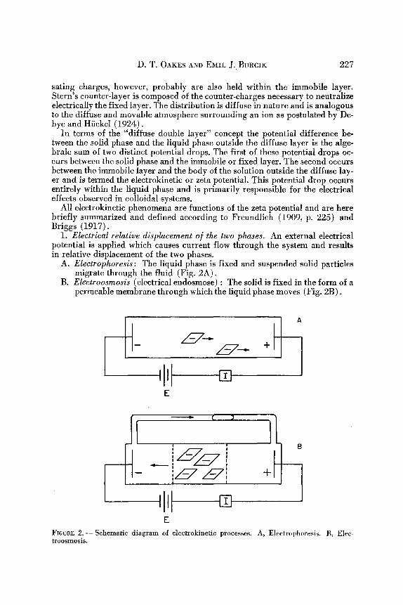
1. Electrical relative displacement of the two phases. An external electrical potential is applied which causes current ftow through the system and results in relative displacement of the two phases.
A. Electrophoresis: The liquid phase is fixed and suspended solid particles migrate through the fluid (Fig. 2A).
B. Electroosmosis (electrical endosmose) : The solid is fixed in the form of a permeable membrane through which the liquid phase moves (Fig. 2B).
_ _ _ . +
E
] I - LSz +
Ill E
FIcuRE 2.--Schematic diagram of eleetrokinetic processes. A, Eleetrophoresis. B, Elec- troosmosis.

228 ELECTROKINETIC PHENOMENA IN COLLOIDAL CLAYS
2. Mechanical relative displacement o i the two phases. Mechanical relative displacement results in the production of a potential difference and consequent current flow through the system.
A. Streaming potential (filtration potential or Quinke's diaphragm currents) : The solid is fixed in the form of a permeable diaphragm through which the liquid is forced. A potential difference and an electric current are established between the ends of the diaphragm.
B. Sedimentation potential (Dorn effect) : The finely divided solid phase is dropped through the liquid to produce the relative displacement of the two phases. A difference in potential and a current flow are established between the upper and lower liquid strata.
Mathematical expression of the relation between the electrokinetic potential and relative motion of the two phases was established by the fundamental gen- eralizations promulgated by Weidemann (1852). The first theoretical deriva- tion was proposed by Helmholtz (1879) using his plane parallel double layer. The experiments of Perrin (1904 and 1905), Freundlich (1909, p. 225) and other investigators (Debye and Hiickel, 1924; Henry, 1931) substantiated the relationship proposed by Hehnholtz. Modification of the derivation was neces- sitated by the wide acceptance of Stern's (1924) diffuse double layer. Hartley (1935) has since shown, however, that the distribution of charge within the diffuse layer makes little, if any, difference in the final equation. In addition it can be shown that on the basis of Stern's theory, if ionic concentration is rela- tively high, the charges within the diffuse counter-layer will be concentrated in a plane closely approaching Helmholtz' counter-layer. Hartley (1935) and Adam ( 1941, p. 351-359) have presented excellent discussions of the details of the charge distribution cited above.
Using the simplifying assumption of Helmholtz' double layer and a cylindrical system such as a capillary tube, Creighton (1924, p. 142-159) presents the following equation along with appropriate units and conversion factors. A more general approach that gives the same resuk is that of Smoluchowski (cited by Adam, 1941, p. 351-359).
Electrokinetic Potential = Z -- 4~r gVL D A E
Eq. 1
where /~ = viscosity coefficient V = volumetric velocity L = length D = dielectric constant A = cross-sectional area E = applied potential
The above expression was derived assuming electroosmotic flow of liquid through a capillary tube. The same formula may be used for calculating elec- trophoretic velocities of cylindrical particles or electroosmotic flow through a colloidal gel composed of longitudinally oriented, cylindrical particles. Kemp (1935) has indicated that while the general relationship above is true, the con-
:stant of proportionality depends on the size and shape of the particles. Since a drilling fluid is composed of particles having a diversity of sizes and shapes, it was assumed that the experimental results would indicate order-of-magnitude values and allow justifiable comparison on a relative basis.
D. T. OAKES AND EMII~ J. BURCIK 229
The addition of contaminating ions to a sol of bentonite results in a complex change in the colloidal particles and their associated double layers which can be attributed to some combination of the following causes:
1. "Debye-HiickeI'" effect. According to Debye and Hiickel (1923) each ion of a strong electrolyte in solution is completely ionized and is surrounded by an ionic atmosphere whose net charge is opposite to that of the central ion. The ionic atmosphere and, consequently, the interaction between the ionic atmos- phere and the central ion, are dependent on the concentration and effective val- ence of the ions in solution. The addition of any electrolyte will then have the effect of increasing the interaction (between the central ion and its atmosphere) and reducing the ionization potential of the central ion. It also can be shown that the effectiveness in repressing the ionization potential increases markedly with increase in valence of the added electrolyte. Further, the potential depres- sion effected by a given increment of concentration will be less than for the equal increment immediately preceding it. Hauser and leBeau (1941) demonstrated that the electrokinetic potential of bentonite clays was depressed with increasing concentration of colloidal material. While some of the depression observed may be attributed to other surface phenomena, the electrical nature of the phase- boundary system (which manifests itself through the electrokinetic potential) demands that a part of this depression be ascribed solely to an increased inter- action between the colloidal bentonite particles and their "ionic atmosphere." Similar repression of the potential as a result of the addition of electrolytes must also be attributed to this "Debye-Hiickel" effect.
2. Increase or decrease in the electrokinetic potential by ion exchange within the fixed layer. While partially discussed in 3, below, ion exchange will here be reviewed. It is often possible for an ion to be attached to a large particle. Such an ion may be attached firmly, but will retain all other properties of an ion, including the requirement that there be a counter-ion in the near vicinity. The adsorbed ions can be removed only by a method which preserves the electro- neutrality of the system. If the particles are washed with a solution containing other ions, the adsorbed ions may be replaced. If the washing process is con- tinued long enough the initially adsorbed ions will be removed and the particles left with the correspondingly charged ions from the solution in their place. This process is known as ion exchange; it may also take place with only ions in the outer layer being exchanged. Considerable data are available citing the ion- exchange capacities for various bentonites (Marshall, 1949, p. 101-151 ; Marshall and Gupta, 1933; Mukherjee, Sen Gupta, and Indra, 1943).
3. Increase or decrease in the electrokinetie potential as a result o I adsorption o I additional ions into the lixed layer. The tendency of ions to be adsorbed generally increases enormously with increase in valency (Jenny and Reitemeier, 1935). It is possible to add ions to a colloidal system in sufficient quantity to reverse the sign of the potential and accordingly reverse the direction of elec- trokinetic migration. The results of Freundlich, Schmidt and Lindau (1932) showed reversal of the sign of the bentonite particles when contaminated with relatively small amounts of thorium chloride and aluminum chloride. Additions of small amounts of potassium and sodium hydroxide resulted in higher elec- trokinetic potentials. It is highly debatable whether this latter effect can be attributed entirely to either adsorption in the fixed layer or ion-exchange proc-
230 ELECTROKINETIC PHENOMENA IN COLLOIDAL CLAYS
esses in the double layer. It is likely a combination of both processes. The effect of the addition of polyvalent salts can likewise be attributed to both processes.
4. Ionization. The role of true ionization in determining the particle potential is not well established. Some authorities (Marshall and Gupta, 1933; Chaney and Oxford, 1946) place considerable emphasis on this effect. Magnitudes of ionization of clays have been established based on equivalence of the metallic cations present (Marshall, 1949, p. 101-151) but few data on bentonite are avail- able. The results are expressed in terms of the cation fraction active. It is believed that these measurements may be either ionization or ion exchange or a combination of both.
5. Dehydration o] the ]ixed layer. If normally highly hydrated ions are added in sufficiently high concentrations, partial dehydration of the fixed layer may take place. Jenny and Reitemeier (1935), however, showed that highly hydrat- ed ions may effectively increase the thickness of the fixed part of the double layer if in sufficient concentration to effect replacement of an unhydrated ion.
MATERIALS, APPARATUS AND PROCEDURE
Preparation o] Materials
A sol of bentonite, in quantity sufficient for all samples used in this investiga- tion, was prepared in a concentration of exactly 60.0 g of dry, commercial Wyoming bentonite per liter (68 ~ F) of freshly distilled water. The batch was vigorously agitated with electric stirrers for approximately two hours and then placed in a single, stoppered glass container. The batch was allowed to hydrate at room temperature for several months during which time it was agitated fre- quently.
Upon completion of the hydration period the batch was again agitated vigor- ously after which the samples were removed. Individual 500-milliliter samples were measured gravimetrically. The individual samples were then contaminated with various quantities of the several contaminants used in this investigation. Among these were sodium chloride, calcium chloride, calcium nitrate, lantha- num chloride, and thorium chloride. The quantities necessary to produce the desired normality were weighed on an analytical balance. Samples were then thermostated in an air bath (30 ~ C) for several weeks during which time they were agitated frequently.
Apparatus
The thixotropic nature of bentonite precludes the use of electrophoretic or sedimentation-potential measurements with concentrations of colloidal clay in excess of 0.10 percent. Of the two remaining possibilities, electroosmosis seemed to offer better prospects than streaming-potential measurements and was accordingly first investigated.
Initial attempts to devise an apparatus so that the gel-strength of the sol was relied upon to support the central colloid section as an immobile diaphragm met with little success. Even when the gelled sol was packed into the interstices be- tween 2-mm glass beads the gel-strength was insufficient and some movement of the colloid section was observed.
The apparatus constructed was schematically similar to the modification of Perrin's (1904, 1905) apparatus as suggested by Briggs, Bennett and Pierson

D. T. OAKES AND EMIL J. BURCIK 231
(1918). Such changes were incorporated as were necessary to adapt the ap- paratus to the investigation of highly concentrated bentonite sols. The dis- tinguishing modification was that the permeable diaphragm was replaced by an artificially constructed "diaphragm." This "diaphragm" consisted of the col- loidal suspension suitably supported by thin membranes (washed lens tissue) of relatively small surface area.
In Figure 3 is reproduced a schematic diagram of the apparatus developed for measurement of the electroosmotic relative movement in bentonite suspensions. The apparatus consists of a U-tube divided into three sections by the membranes, M. The center section, SS, contains the colloidal suspension which is effectively immobilized by the membranes at either end. The two vertical legs, LS, are filIed with soI liquor to above the electrodes, K, and side-outlets.
The exterior circuit between stopcocks, S, is a calibrated tube filled with nonconducting, freshly distilled water and containing a large air bubble, B.
S j
I S
~=
2sj FIGURE 3 . - - E l e c t r o o s m o s i s appa ra tus .
232 ELECTROKINETIC PHENOMENA IN COLLOIDAL CLAYS
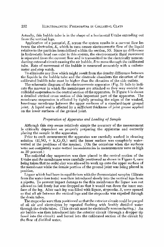
Actually, this bubble tube is in the shape of a horizontal U-tube extending out from the vertical legs.
Application of a potential, E, across the system results in a current flow be- tween the electrodes, K, which in turn causes electroosmotic flow of the liquid relative to the particles immobilized within the section, SS. Since no difference in hydrostatic head can exist in this system, the electroosmotic fluid movement is separated from the current flow and is transmitted to the electrically noncon- ducting external circuit causing the air bubble, B to move through the calibrated tube. Rate of movement of the bubble is measured accurately with a catheto- meter and stop watch.
To eliminate any flow which might result from the density difference between the liquids in the bubble tube and the electrode chambers the elevation of the calibrated bubble tube must be higher than the elevation of the side outlets.
The schematic diagram of the electroosmosis apparatus (Fig. 3) fails to indi- cate the manner in which the membranes are attached so they may restrict the colloidal suspension to the central section of the apparatus. In Figure 4 is shown a detailed vertical cross section of this important part of the apparatus. The membrane suspension is effected by tightly pressing the edges of the washed, lens-tissue membrane between the upper surfaces of a standard-taper ground joint. A liquid seal is effected by a sufficient thickness of joint grease applied on the lower surfaces of the ground joint.
Preparation o] Apparatus and Loading o] Sample
Although this step seems relatively simple the accuracy of the measurement is critically dependent on properly preparing the apparatus and correctly placing the sample in the apparatus.
Prior to each measurement the apparatus was carefully washed in cleaning solution (H2SO4 d- K2CrzO~) until the inner surface was completely water- wetted at the positions of the menisci. (On the occasions when the surfaces were not completely water-wetted inconsistencies in measurements were as high as 20 percent.)
The colloidal clay suspension was then placed in the central section of the U-tube and the membranes were carefully positioned as shown in Figure 4, care being taken that no solid clay was allowed to work up onto the upper surface of the membrane while the female portion of the ground joint was being placed in position.
Liquor which had been in equilibrium with the thermostated samples (filtrate from the water-loss tests) was then introduced slowly into the vertical legs from a pipette. To prevent impact damage to the thin membranes the liquor was not allowed to fall freely but was dropped so that it would run down the inner sur- face of the leg. After each leg was filled with liquor, stopcocks, S, were opened so that all air between the vertical legs and the stopcocks was expelled through the drain tubes.
The stopcocks were then positioned so that the exterior circuit could be purged of all air and electrolytes by repeated flushing with freshly distilled water through the drain tubes. (This circuit must be electrically nonconducting.) An air bubble was then introduced into the exterior circuit (through a dropper tip fused into the circuit) and forced into the calibrated section of the circuit by the flow of distilled water.

D. T. OAKES AND EMIL J~ BURCIK
/ P Y R E X J O I N T
233
M E M B R A N E
J O I N T G R E A S E
F I G U R E 4 . - - Joint detail.
The apparatus was then immersed in a water bath and allowed to remain until thermal equi l ibr ium was obtained at 30 ~ C.
Measurement Procedure
The cathetometer cross hair was so placed that a few seconds after the current was started and the bubble velocity became constant the bubble in the exterior circuit would pass under the cross hair . A stop watch was started and the applied voltage, current flow, temperature and cathetometer reading were recorded. At 30-second or one-minute intervals the readings of appl ied voltage, current flow and temperature were recorded. The cathetometer was moved a given dis- tance (in the direction of the bubble movement) past the bubble and posit ioned. When the bubble again passed under the cross hair the final readings of voltage,

234 ELECTROKINETIC PHENOMENA IN COLLOIDAL CLAYS
amperage, temperature, t ime and total distance of bubble movement were re- corded. Thus, the volumetric rate of l iquid flow through the system was re- corded along with the applied potential and current flow which induced the l iquid flow.
Polar i ty of the electrodes was reversed and the procedure was repeated with the bubble (and the l iquid) moving in a direction opposite to the former run.
The applied potential used to induce electroosmotic flow was var ied from 10 to 100 volts depending on the concentration of the contaminant. Uncontamin- ated muds were of sufficiently low eonductivities that I00 volts did not produce excessive heat ing or foaming at the electrodes while at high ion concentrations it was found necessary to reduce the applied potential to prevent heating or the formation of stable foams about the negative electrode.
I t was original ly believed that some correction might be required to allow for electroosmotie flow at tr ibutable entirely to the tissue membranes. Subsequent tests showed no discernible electroosmotic flow when no bentonite was present in the central chamber, regardless of the concentration or valency of the con- taminant within the system.
Fi l t ra t ion tests were made with a wall bui lding tester. This is a simple cylin- drical pressure filter which has a filter area of 7.1 square inches. The top of the cell is f i t ted with a gasket and a machined cap which has a small hole for ad- mission of air pressure. The bottom of the cell is closed by a sheet of Whatman no. 50 filter paper backed by a wire screen and a bot tom cap with gaskets to provide an effective seal (Rogers, 1953, p. 112-116). The rate at which fluid is forced from the filter is usually expressed as mill i l i ters per 30 minutes at a given temperature and pressure.
o
N
p-
o
~-o
~J N
U_ 0
Q::
~ X
0 CoCI 2
�9 C o(N03) 2 'l( C a Cl2(Ft eundl ich )
o i .018 1 0 . 0 4 .12
C O N C E N T R A T I O N ~ N '
!
16
FIGURE 5.--Repression of the electrokinetic potential by the addition of calcium ions.

D. T. OAKES AND EMIL J. BURClI< 235
RESULTS AND DISCUSSION
The importance of the eleetrokinetic potential in colloidal systems has long been recognized. Numerous investigators have shown that the stability of col- loidal systems as well as other related physical characteristics are largely de- pendent on this electrical property. Accordingly, extensive investigations of many colloidal systems have been made and the viscosity and stability as func- tions of zeta potential have been accurately determined.
Studies of colloidal suspensions of bentonite, unfortunately, do not lend them- selves readily to electrokinetic investigations because of their thixotropic charac- ter. Using cataphoresis, Hauser and leBeau (1941) investigated the effect of clay concentration on the zeta potential for carefully sized fractions of bentonite. They observed that the zeta potentials remained essentially constant up to a clay concentration of about 0.40 percent and were decreased thereafter almost proportionally with increasing clay concentration. This repression of the zeta potential and/or perhaps the reduction of the dielectric constant is also demonstrated by the work of Freundlich, Sehmidt and Lindau (1932). Since the object of this investigation was the study of electrokinetie phenomena in high concentration ranges, the described electroosmotic technique was neces- sarily used.
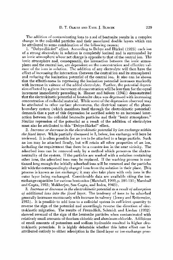
In Figure 5 is presented the effect of the calcium ion on the zeta potential of a 6 percent bentonite sol. The results obtained with CaC12 and Ca (NO3)2 show that any deviation attributable to the anion is less than the experimental error of the technique. For comparison purposes the data of Freundlich, Schmidt, and
O O
e NaCl z "\ ~ ~ NoCl(Freundlich)
0. r \ 1 ~ t (A lC l3(Freund l lch)
0 m N
7- N. \ \
0 I ~ 1 r I I I 0 04, 08 12 .16
CONCENTRATION, N ~
FICURE 6 . - Repression of the eleetrokinetic potentia] by the addition of sodium and lantha- n u n l ions.

236 ELECTROKINETIC PHENOMENA IN COLLOIDAL CLAYS
Lindau (1932) are presented. In order to make this comparison (since no com- parable data on concentrated bentonite sols are available) it was necessary to establish comparable units of electrokinetic potential and contaminant con- centration. Accordingly, the potential expression, Z/Zo, was established. This represents the ratio of the zeta potential, Z, to the zeta potential of zero contam- ination. This expression indicates fractional repression of the zeta potential and is applicable to either electroosmotic or cataphoretic data. It also has the advantage of eliminating instrument calibration constants which vary with the method used.
It is generally agreed that the method selected for expressing the concentra- tion should be most representative of the action being studied. The contami- nating salts were added on a molal basis (moles solute per 1000 g solvent) since the water was already present in the suspension thus making molar additions impossible. Molality does not account for varying valence of the units of the molecule so solutions of equal molality are not necessarily chemically equiva- lent. A concentration expression analogous to normality was adopted which can here be defined as the molality divided by the cation valence. This ratio is designated N'. To put Freundlich's data in comparable concentration units (with respect to bentonite concentrations) it was necessary to convert the original data to N' and multiply by the ratio of colloidal material contaminated.
The electrokinetic potentials are rapidly reduced, but at a decreasing rate, by the addition of small concentrations of calcium ion (Fig. 5). Even though the data of Freundlich can be used only for qualitative comparisons, the curves are similar and show changes of comparable magnitude.
Insufficient data were obtained in this investigation on sodium chloride and lanthanum chloride (Fig. 6) to establish any extensive comparison. The ad- dition of these salts resulted in potential depression of less magnitude than the depressions observed by Freundlich. As was indicated above, this repression can be a function of any number of at least five mechanisms: Debye-Hiickel depression, ionization, adsorption of ions within the fixed layer, ion exchange, and dehydration of the fixed layer.
The behavior of ThC14 in repressing the zeta potential was found to be quite interesting in that the repression was considerably less than expected. Data for two different Wyoming bentonites are presented in Table 1 along with the corresponding values for CaC12 contamination. These values are in disagree- ment with the well-known "Schulze-Hardy" rule which generalizes that the effec-
TABLE 1.--REPRESSION OF ELECTROKINETIC POTENTIAL BY THORIUM CHLORIDE.
Conc. Z / Z o Z / Z o Clay Nt CaC121 ThC14
0 1.000 1.000 A .8050 .910 .924 A .0125 .830 .805 A .0250 .740 .794 A
0 1.000 1.000 B .0100 .827 .923 B .0300 .728 .770 B .0600 .566 .536 B
1 From Figure 5

D. T. OAKES AND EMIL J. BURCIK 237
tiveness (in adsorption and coagulation) increases with the valency. Runs for Clay B were repeated because of this anomalous behavior. Excellent duplica- tion of the data was observed, the values varying only 3.5, 5.0 and 1.4 per- cent. This can possibly be explained by partial ionization of the thorium salt. It is a well-known principle that, in an electrolyte composed of one qua& rivalent and four univalent ions, ionization of successive univalent ions from the molecule becomes successively more difficult. It might well happen that a cation, (ThClz)2+, would represent the effective unit of dissociation of thorium chloride in a system of this nature. Another possible explanation of this be- havior can be based on the degree of hydration of the cation. Whether reducing the zeta potential by adsorption into the fixed layer or by ion exchange, the more highly hydrated cation is attached more loosely and produces correspond- ingly higher zeta potentials (Jenny and Reitemeier, 1935).
The characteristic of low water-loss is of considerable interest in a study of the electrokinetics of highly concentrated colloidal clays. Since the flow of fluids past colloidal particles which are tightly packed together (in the filter cake which has clay concentrations as high as 15 percent in the uncompressed state) must necessarily displace ions in the diffuse layer from their equilibrium positions, it seems likely that the work necessary to overcome these forces would depend on the zeta potential. Reduction in the potential would allow the packed cake to pass a greater amount of water and an increase would, up to a certain limit, tend to restrict the flow. Further, if other forces restricting flow are of the same magnitude (for example, permeability due strictly to particle size) the rate of filtration should be inversely proportional to the electrical forces overcome. If this is the case, the water-loss should be an inverse func- tion of the ratio of zeta potentials. Further, the particular electrolytes present
t-4
I-- z bJ I--
N
0
0
o
o
�9 ~ I n l t , a l C l a y S o l �9 N a C I
x ThCI 4 O C o C I 2 �9 Co(N03) z B L o C I 3
I ! i I I
0 2 0 4 0 6 0 8 0 1 0 0
3 0 - M I N U T E W A T E R - L O S S , mL a t 3 0 ~ a n d 5 0 p s i
FXGURE 7 . - Water loss as a funct ion of electrokinetic potential.
I
120

238 ELECTROKINETIC PHENOMENA IN COLLOIDAL CLAYS
o N
N
l--
a_
LJJ N L,- o o i - -
0
0 0
0 G
0 C a CI?_
�9 N a C t
0 I I I |
0 2 O 4 O 6 0 8 0
5 0 - M I N U T E W A T E R - L O S S ~ m l a t 3 0 a C . a n d I O O p s i
FIGURE 8 . - Water loss as a function of electrokinetic potential.
and causing depression of the zeta potential should make no difference so long as they do not cause other changes in the system. In Figure 7 is presented the water-loss of all samples tested as a function of the potential ratio. These in- clude sodium chloride, calcium chloride, calcium nitrate, lanthanum chloride and thor ium chloride. The t rend established by water-loss against the potential ratio appears to substantiate to a degree the val idi ty of the above-cited relation. In the low concentration-high potential range, however, deviation from a l inear relat ionship is observed. A change in the f low mechanism seems to take place in this region. In Figure 8 are presented the water-loss zeta-potential data for a 6 percent sol of a different Wyoming bentonite. In this case only NaC1 and CaCI 2 were added to the various samples. I t may be observed that the general shape of the curve remains the same as in F igure 7.
REFERENCES
Adam, N. K., 1941, ~'he physics and chemistry of surfaces (3d ed.) : Oxford University Press, London, 436 p.
Briggs, T. R., 1917, Electrical endosmose, I: J. Phys. Chem., v. 21, p. 198-237. Briggs, T. R., Bennett, H. S., and Pierson, H. L., 1918, Electrical endosmose, II: J. Phys.
Chem., v. 22, p. 256-272. Chaney, P. E., and Oxford, W. F., 1946, The chemical treatment of drilling fluids: A. and
M. College of Texas, Bull. 96, 93 p. Creighton, H. J., 1943, Principles of electrochemistry, v. 1; John Wiley & Sons Inc., New
York, 477 p. Debye, P., and Hiickel, E., 1923, Zur Theorie der Electrolyte: Phyzikal. Z., v. 24, p. 185-206.
,1924, Bemerkungen zu einem S~itze iiber die kataphoretische wanderungsgeschwindig- keit suspendierter Teilchen: Phyzikal. Z., v. 25, p. 49-52.

D. T. OAKES AND EMIL J. BURCIK 239
Freundlich, H., 1909, Kapillarchemie: Leipzig, 1181 p. Freundlioh, H., Schmidt, O., and Lindau, G., 1932, 13ber die Thixotropie yon Bentonit-
Suspensionen: Kolloid-Beihefte, v. 36, p. 43-81. Hartley, G. S., 1935, The application of the Debye-Hiickel theory to colloidal-electrolytes:
Faraday Soc. Trans., v. 31, p. 31-50. Hauser, E. A., and leBeau, D. S., 1941, Studies in colloidal clays. II: J. Phys. Chem., v. 45,
p. 54-65. Helmholtz, H., 1879, Studien fiber elektrische Grenschichten: Ann. Physik, v. 7, p. 337-382. Henry, D. C., 1931, The cataphoresis of suspended particles: Proc. Roy. Soc. A, v. 133, p.
106-140. Jenny, H., and Reitemeier, R. F., 1935, Ionic exchange in relation to the stability of colloidal
systems: J. Phys. Chem., v. 39, p. 593-604. Kemp, I., 1935, On the relation between particle size and cataphoretic mobility: Faraday
Soc. Trans., v. 31, p. 1347-1357. Marshall, C. E., 1949, Colloid chemistry of the silicate minerals: Academic Press, New
York, 180 p. Marshall, C. E., and Gupta, R. S., 1933, Base exchange equilibria in clays: J. Soc. Chem.
Ind., v. 52, p. 433T. Mukherjee, J. N., Sen Gupta, N. C., and Indra, M. K., 1943, Effect of concentration and pH
on the viscous and electrochemical properties of hydrogen bentonite: J. Phys. Chem., v. 47, p. 553-577.
Perrin, J., 1904, M6canisme de l'61ectrisation de contact et solutions colloYdales: J. Chem. Phys., v. 2, p. 601-551.
- - , 1905, M6canisme de l'electrisation de contact et solutions colloYdales : J. Chem. Phys., v. 3, p. 50-110.
Rogers, W. F., 1953, Composition and properties of oil well drilling fluids (revised) : Gulf Publishing Co., Houston, 676 p.
Stern, 1924: Z. Elektrochem., v. 30, p. 508. Weidemann, G., 1852, ~ber die Bewegung yon Flfissigkeiten im Kreise der geschlossenen
galvanischen S~iulc: Pogg. Ann., v. 87, p. 321-352. ,1856, l~ber die Bewegung yon Fliissigkeiten im Kreise der geschlossenen galvanischen
S~iule und i.hre Beziehungen zur Electrolyse: Pogg. Ann., v. 99, p. 177-233.