Electrohydraulics Basic Level - Festo · PDF fileEquipment set for Basic Level TP 601 23 ......
42
Workbook TP 601 Festo Didactic 094470 en Electrohydraulics Basic Level
Transcript of Electrohydraulics Basic Level - Festo · PDF fileEquipment set for Basic Level TP 601 23 ......
Workbook TP 601
Festo Didactic
094470 en
ElectrohydraulicsBasic Level

TP601 • Festo Didactic
Authorised applications and liability
The Learning System for Automation and Communication has been de-veloped and prepared exclusively for training in the field of automation and communication. The training organization and / or trainee shall en-sure that the safety precautions described in the accompanying Techni-cal documentation are fully observed.
Festo Didactic hereby excludes any liability for injury to trainees, to the training organization and / or to third parties occurring as a result of the use or application of the station outside of a pure training situation, unless caused by premeditation or gross negligence on the part of Festo Didactic.
Order no.: 094470 Description: TEACHW. E-HYDR. Designation: D.S601-C-SIBU-GB Edition: 07/2003 Layout: 04.07.2003, OCKER Ingenieurbüro Graphics: OCKER Ingenieurbüro Author: D. Merkle, H. Werner
© Festo Didactic GmbH & Co. KG, 73770 Denkendorf, Germany, 2003
The copying, distribution and utilization of this document as well as the communication of its contents to others without expressed authorization is prohibited. Offenders will be held liable for the payment of damages. All rights reserved, in particular the right to carry out patent, utility model or ornamental design registrations.
Parts of this training documentation may be duplicated, solely for training purposes, by persons authorised in this sense.
TP601 • Festo Didactic
3
Preface
Festo Didactic’s Learning System for Automation and Communicationsis designed to meet a number of different training and vocational re-quirements. The Training Packages are structured accordingly:
� Basic Packages provide fundamental knowledge which is not limitedto a specific technology.
� Technology Packages deal with the important areas of open-loop andclosed-loop control technology.
� Function Packages explain the basic functions of automation sys-tems.
� Application Packages provide basic and further training closely ori-ented to everyday industrial practice.
Technology Packages deal with the technologies of pneumatics, elec-tropneumatics, programmable logic controllers, automation with PCs,hydraulics, electrohydraulics, proportional hydraulics and applicationtechnology (handling).
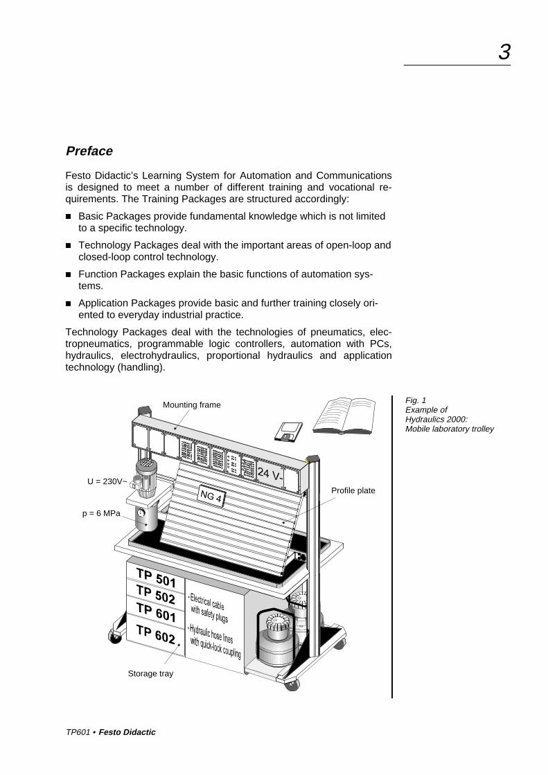
Fig. 1Example ofHydraulics 2000:Mobile laboratory trolley
Mounting frame
Profile plateU = 230V~
p = 6 MPa
Storage tray

TP601 • Festo Didactic
4
The modular structure of the Learning System permits applications to beassembled which go beyond the scope of the individual packages. It ispossible, for example, to use PLCs to control pneumatic, hydraulic andelectrical actuators.
All training packages have an identical structure:
� Hardware
� Courseware
� Software
� Courses
The hardware consists of industrial components and installations,adapted for didactic purposes.
The courseware is matched methodologically and didactically to thetraining hardware. The courseware comprises:
� Textbooks (with exercises and examples)
� Workbooks (with practical exercises, explanatory notes, solutions anddata sheets)
� OHP transparencies, electronic transparencies for PCs and videos(to bring teaching to life)
Teaching and learning media are available in several languages. Theyhave been designed for use in classroom teaching but can also be usedfor self-study purposes.
In the software field, CAD programs, computer-based training programsand programming software for programmable logic controllers are avail-able.
Festo Didactic’s range of products for basic and further training is com-pleted by a comprehensive selection of courses matched to the contentsof the technology packages.

TP601 • Festo Didactic
5
Latest information about the technology package TP601.
New in Hydraulic 2000:
� Industrial components on the profile plate.
� Exercises with exercise sheets and solutions, leading questions.
� Fostering of key qualifications:Technical competence, personal competence and social competenceform professional competence.
� Training of team skills, willingness to co-operate, willingness to learn,independence and organisational skills.
Aim – Professional competence
Content
Part A Course Exercises
Part B Fundamentals Reference to the text book
Part C Solutions Function diagrams, circuits, descriptions ofsolutions and quipment lists
Part D Appendix Storage tray, mounting technologyand datasheets

TP601 • Festo Didactic
6

TP601 • Festo Didactic
7
Table of contents
Introduction 11
Notes on safety 13
Notes on operation 14
Technical notes 15
Training contents 21
Training aims/exercise table (Table 1) 22
Equipment set for Basic Level TP 601 23
Equipment set for Advanced Level TP 602 26
List of additional components for TP600 27
Component/exercise table (Table 2) 28
Methodological structure of exercises 29
Part A – Course
Simple control circuits without limit switches
Exercise 1: Sorting deviceDouble-acting cylinder,directly actuated, manually A-3
Exercise 2: Component selection on conveyor beltDouble-acting cylinder,indirectly actuated, manually A-13
Exercise 3: Lifting stationSingle-acting cylinder,indirectly actuated, manually A-23
Exercise 4: Bending deviceDouble-acting cylinder, latching A-29
Exercise 5: Press-fitting deviceDouble-acting cylinder, latching,return stroke using pressure switch A-33

TP601 • Festo Didactic
8
Exercise 6: Stamping machineDouble-acting cylinder, differential circuit A-39
Exercise 7: Door controlDouble-acting cylinder, interlock,INCHING operation A-43
Control circuits with limit switches
Exercise 8: Machining unitDifferential circuitreturn stroke using limit switch A-49
Exercise 9: Feed for drilling machineRapid-traverse feed circuit,speeds controlled by limit switch A-53
Exercise 10: PressPressure control circuit with limit switchand pressure switch A-59
Exercise 11: Feed devicePressureless pump bypass with limit switch A-63
Control circuits with two actuators
Exercise 12: Assembly devicePressure-dependent sequence control withcylinder and hydraulic motor A-69
Exercise 13: Lifting device for packagesPosition-dependent sequence controlwith two cylinders A-75

TP601 • Festo Didactic
9
Part B – Fundamentals
Teil C – Solutions
Solution 1: Sorting device C-3
Solution 2: Component selection on conveyor belt C-7
Solution 3: Lifting station C-11
Solution 4: Bending device C-15
Solution 5: Press-fitting device C-19
Solution 6: Stamping machine C-23
Solution 7: Door control C-27
Solution 8: Machining unit C-33
Solution 9: Feed for drilling machine C-39
Solution 10: Press C-45
Solution 11: Feed device C-49
Solution 12: Assembly device C-55
Solution 13: Lifting device for packages C-61
Part D – Appendix
Storage tray D-2
Mounting systems D-3
Sub-base D-5
Coupling system D-6
Data sheets ...

TP601 • Festo Didactic
10

TP601 • Festo Didactic
11
Introduction
This workbook forms part of Festo Didactic’s Learning System for Auto-mation and Communications. The Training Package TP 600 is designedto provide an introduction to the fundamentals of electrohydraulic controltechnology. This package comprises a basic level and an advancedlevel. The basic level package TP 601 teaches basic knowledge ofelectrohydraulic control technology. The equipment sets TP 601 and TP602 (for the advanced level) provide the student with the key qualifica-tion “Technical competence”.
The hydraulic components have been designed to provide the following:
� Easy handling
� Secure mounting
� Environmentally-friendly coupling system
� Compact component dimensions
� Authentic measuring methods
You will require the following for the practical execution of the exercises:
� A Festo Didactic profile plate or a laboratory trolley
� An equipment set TP 601 (cylinders, valves, relay plate, ...)
� A hydraulic power pack
� A number of hydraulic hose lines
� An electrical power supply unit
� A set of electrical cables
The Training Package TP 601 specifies fundamental training contents.These help develop both technical and methodological competence inelectrohydraulics:
� Physical interrelationships in electrical engineering and hydraulics
� Drafting, assembly and understanding of basic electrohydraulic cir-cuits
� Comparison of the use of various valves and other components
� Development of alternative solutions

TP601 • Festo Didactic
12
The technical requirements for safe operation of the components are asfollows:
� A hydraulic power pack to provide an operating pressure between0.5 and 6 Mpa (5 to 60 bar) and a flow rate of 2 l/min.
� An electrical power supply for the above of 230 V AC, 50 Hz, with a10 A fuse.
� A short-circuit-proof electrical power supply for the electrical compo-nents with an output of 24 V DC and a 3 A fuse.
� A profile plate to mount the componentsThe profile plate (1100 x 700 mm) has 14 parallel T-grooves at inter-vals of 50 mm.
This workbook has been developed for use in the “Dual system” of vo-cational training. It is, however, equally suitable for use in providing apractical introduction to electrohydraulics for students at universities andtechnical colleges. The modular design of the hardware allows theoreti-cal questions to be dealt with experimentally in a simple and efficientform.
The theoretical background to facilitate understanding of this workbookis provided in the textbook
Learning System for Automation and Communications
� Electrohydraulics Basic Level
Festo Didactic also offers the following further training materials for hy-draulics:
� Sets of OHP transparencies and electronic transparencies for PCs
� Linear videos and interactive videos (video discs)
� Autosketch CAD software and symbol library
� Hydraulics simulation program for planning, simulation and visualisa-tion (in course of preparation)
� Sets of magnetic symbols and symbols for OHPs, hydraulic slide rule
� Transparent models for OHPs, with special hydraulic power pack
� Equipment sets: BIBB, hand-lever hydraulics, proportional hydraulics,closed-loop hydraulics, measurement kit in case
Please see our special brochures for a detailed description of furthertraining materials.
TP601 • Festo Didactic
13
Notes on safety
Observe the following in the interests of your own safety:
� Caution!Cylinders may move unexpectedly when the hydraulic power pack isswitched on.
� Do not exceed the maximum permissible hydraulic operating pres-sure. See the relevant data sheets.
� Do not operate electrical limit switches directly by hand when carryingout fault-finding. Use a tool for this.
� Use only an extra-low voltage of 24 to operate the components.
� Observe all general safety instructions.

TP601 • Festo Didactic
14
Notes on operation
Assembly
Always work in the following sequence when assembling or dismantlingan electrohydraulic circuit.
1. The hydraulic power pack and electrical power supply must beswitched off during the assembly of the circuit.
2. All components must be securely fitted to the profile plate or mount-ing frame.
3. Connect up the hydraulic hose lines.All valves, other components and hose lines are fitted with self-closing quick-acting couplings. Do not exceed the maximum permis-sible pressure of 12 MPa (120 bar). The maximum operating pres-sure is 6 MPa (60 bar).
4. Connect up the electrical cables.Connect test leads to the component sockets by means of 4 mmplugs.
5. Before commissioning a hydraulic control circuit, check that all returnlines are connected and that all connectors are secure.
6 Switch on the electrical power supply first and then the hydraulicpower pack.
7. Commissioning the control circuit– Press the START pushbutton– Set components, etc.– Compare what you have assembled with the description in thebook.
Dismantling
8. Before dismantling the circuit, ensure that pressure in hydraulic com-ponents has been released:
Couplings must be disconnected only under zero pressure!
9. Switch off the hydraulic power pack first and then the electrical powersupply.

TP601 • Festo Didactic
15
Technical notes
Observe the following in order to ensure safe operation.
� The hydraulic power pack incorporates an adjustable pressure reliefvalve. In the interests of safety, the pressure is limited to approx.6 MPa (60 bar). Every time a control circuit is assembled on the pro-file plate, a second pressure relief valve is used. We recommend thatthis should be set to a maximum pressure of 5 MPa (50 bar).
� All valves, cylinders and hose lines are fitted with quick-acting cou-plings which ensure minimum leakage. The maximum pressure for allcomponents in the training package is 12 MPa (120 bar). Thanks totheir design, the couplings reduce leakage during connection anddisconnection to a minimum.
The operating pressure should not exceed 6 MPa (60 bar)
� In the case of double-acting cylinders, the pressure intensificationeffect may produce an increased pressure proportional to the arearatio of the cylinder. With an area ratio of 1:1.7 and an operatingpressure of 6 MPa (60 bar), this increased pressure may be over10 MPa (100 bar)!
� If connections are detached under pressure, the non-return valve inthe coupling may cause pressure to become trapped in the valve orother component concerned. The pressure relief device can be usedto release this pressure. Exception: This is not possible in the case ofhose lines and non-return valves. Ensure therefore that control cir-cuits are depressurised before hose lines are disconnected and thecircuit is dismantled.
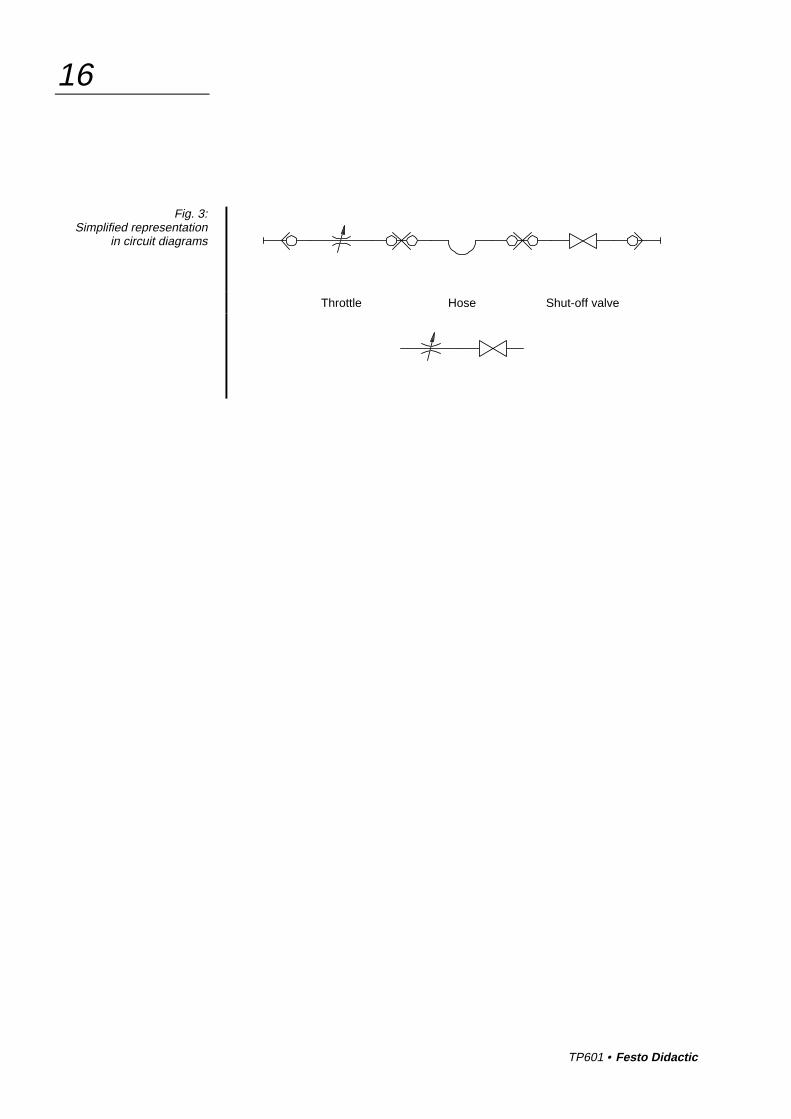
� All valves, other components and hose lines are fitted with self-closing quick-acting couplings. This prevents the accidental spillageof hydraulic fluid. In the interests of simplicity, these couplings are notshown in circuit diagrams.
Fig. 2:Pressure intensification
TP601 • Festo Didactic
16
Throttle Hose Shut-off valve
Fig. 3:Simplified representation
in circuit diagrams
TP601 • Festo Didactic
17
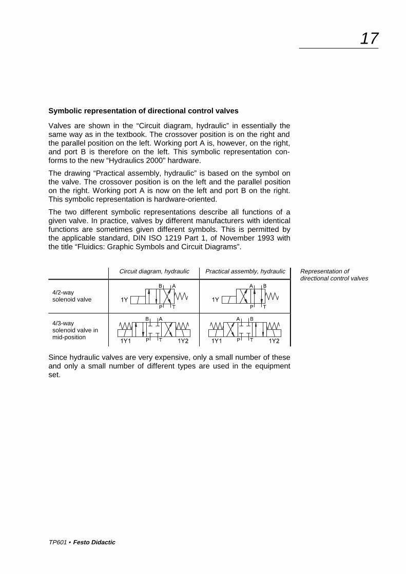
Symbolic representation of directional control valves
Valves are shown in the “Circuit diagram, hydraulic” in essentially thesame way as in the textbook. The crossover position is on the right andthe parallel position on the left. Working port A is, however, on the right,and port B is therefore on the left. This symbolic representation con-forms to the new “Hydraulics 2000" hardware.
The drawing “Practical assembly, hydraulic” is based on the symbol onthe valve. The crossover position is on the left and the parallel positionon the right. Working port A is now on the left and port B on the right.This symbolic representation is hardware-oriented.
The two different symbolic representations describe all functions of agiven valve. In practice, valves by different manufacturers with identicalfunctions are sometimes given different symbols. This is permitted bythe applicable standard, DIN ISO 1219 Part 1, of November 1993 withthe title “Fluidics: Graphic Symbols and Circuit Diagrams”.
Circuit diagram, hydraulic Practical assembly, hydraulic
4/2-waysolenoid valve
4/3-waysolenoid valve inmid-position
Since hydraulic valves are very expensive, only a small number of theseand only a small number of different types are used in the equipmentset.
Representation ofdirectional control valves

TP601 • Festo Didactic
18
The 4/2-way valve can be used to produce four further basic functions.
Basic functionin “Circuit diagram, hydraulic”
Connection of 4/2-way solenoid valvein "Practical assembly, hydraulic"
2/2-way valve withclosed in neutral position
2/2-way valve withflow in neutral position
3/2-way valve withclosed in neutral position
3/2-way valve withflow in neutral position
Ports on the directional control valve which are not required are sealedby the self-closing coupling nipples. It is not necessary to seal theseports by means of plugs.

TP601 • Festo Didactic
19
The 4/3-way valve with closed mid-position fulfils various different func-tions in the exercises in this book.
Function of solenoid valvesin “Circuit diagram, hydraulic”
Connection of 4/3-way solenoid valvein "Practical assembly, hydraulic"
No electrical connection ismade to solenoid 1Y2
Solenoid 1Y2 must beactivated in “Practicalassembly, electrical” via anadditional path.
No electrical connection ismade to solenoid 1Y2.
or
No electrical connection ismade to solenoid 1Y1

TP601 • Festo Didactic
20
Electrical
Power supply:230 VAC, 50 Hz
� The hydraulic power pack is protected by a 10 A fuse.
� The short-circuit proof electrical power supply has a 3 A fuse.
� The output voltage of this power supply is 24 V DC.
� The output current is limited to a maximum of 4.5 A.
Wiring:
Universal cable set: 61 red and 37 blue laboratory cables in 5 lengths.All electrohydraulic components are equipped with 4 mm sockets. Theelectrical connections for these components are made using the labora-tory cables with 4 mm plugs.
A distinction should be made between the two designs of electrical limitswitches:
� Electrical limit switch, actuated from the left .
� Electrical limit switch, actuated from the right .
� When cylinder piston speeds are high, the limit switches should beactuated by cylinder cams only in the specified direction.
� Limit switches must not be actuated from the front.
� Both types of limit switches are shown by the same symbol in thehydraulic and electrical circuit diagrams.

TP601 • Festo Didactic
21
Training contents
� Basic physical principles of electrical engineering and hydraulics
� Function and use of electrical and electrohydraulic components suchas switches, pushbuttons and solenoid valves
� Naming and identifying electrical and hydraulic symbols
� Development and reading of standard circuit diagrams
� Representation of control exercises as function diagrams
� Drafting, assembly and commissioning of basic circuits
� Direct and indirect activation of cylinders
� Activation of a hydraulic motor
� MANUAL and AUTOMATIC modes
� Position and pressure dependent control circuits
� Interlock circuit
� Rapid-traverse circuit
� Fault-finding with simple electrohydraulic control circuits
� Function and use of electronic sensors,hydraulic motors and hydraulic accumulators
� Complex sequence controls
� Combination position and pressure dependent control circuits
� Electrical control circuit with several actuators
� Sequence controls with MANUAL/AUTOMATIC,EMERGENCY STOP and SETTING modes
� Circuit with hydraulic accumulator
� Position and time dependent control circuits
� Systematic fault-finding in electrohydraulic control circuits
� Development of sequence controls from a function diagram
� Controls with timer relays with pick-up and drop-off delays
� Counter controls with predetermining counters
Basic Level(TP601)
Advanced Level(TP602)

TP601 • Festo Didactic
22
Training aims/exercise table (Table 1)
Training aims Exercise
1 2 3 4 5 6 7 8 9 10 11 12 13
Actuation of double-actingcylinders • • • • • • • • • • • •
Actuation of single-actingcylinders •
Actuation of ahydraulic motor •
Direct actuation •
Indirect actuation • • • • • • • • • • • •Control circuit operatedmanually • • •
Control circuit with latching • •
Use of a pressure switch • • •Production of a differentialcircuit • •
Interlock circuit •
INCHING operation •
Use of limit switches • • • • • •
Rapid-traverse feed circuit • •
Pressureless pump bypass •
List of training aims

TP601 • Festo Didactic
23
Equipment set for Basic Level TP 601
This equipment set has been compiled for use in basic training in elec-trohydraulic control technology. The set can be combined in any desiredway with other equipment sets from the Festo Didactic Learning System.
Description Order No. Qty.
Pressure gauge 152841 3
One-way flow control valve 152843 1
Non-return valve, 1 bar 152845 1
Non-return valve, 5 bar 152846 1
Branch tee 152847 8
Pressure relief valve, pressure sequence valve 152848 2
2-way flow control valve 152851 1
Non-return valve, piloted 152852 1
Double-acting cylinder, 16/10/200 152857 1
Hydraulic motor, 8 l/min 152858 1
Loading weight, 9 kg 152972 1
Relay, 3-fold* 162241 2
Signal input unit, electrical* 162242 1
Indicator and distributor unit, electrical * 162244 1
4/2-way solenoid valve 167082 1
4/3-way solenoid valve closed in mid-position 167083 1
Limit switch, electrical, actuated from the right 183322 2
Limit switch, electrical, actuated from the left 183345 2
We recommend Order No. Qty.
Hose line with quick-release coupling, 600 mm 152960 10
Hose line with quick-release coupling, 1000 mm 152970 8
* These components can be mounted in the mounting frame or, by using the adapterset (Order No. 35651), on the profile plate.
Order No.: 184463 forequipment set TP 601

TP601 • Festo Didactic
24
Pressure gauge One-way flow control valve
Non-return valve, 1 bar resp. 5bar Pressure relief valve,pressure sequence valve
2-way flow control valve Non-return valve, piloted
Double-acting cylinder, 16/10/200 Hydraulic motor, 8 l/min
Weight, 9 kg Relay, 3-fold
Symbols forequipment setTP 601

TP601 • Festo Didactic
25
Signal input unit, electrical
Indicator and distributor unit, electrical Limit switch, electrical,actuated from the left or from the right
4/2-way solenoid valve 4/3-way solenoid valveclosed in mid-position
Symbols forequipment setTP 601

TP601 • Festo Didactic
26
Equipment set for Advanced Level TP 602
This equipment set has been compiled for advanced-level teaching ofelectrohydraulic control technology. The two equipment sets TP 601 andTP602 can be expanded in any desired way with other equipment setsfrom Festo Didactic’s Learning System for Automation and Communica-tions.
Description Order-No. Qty.
Relay, 3-fold* 162241 2
Timer relay, 2-fold* 162243 1
Predetermining counter, electrical, additive * 162355 1
Indicator and distributor unit, electrical * 162244 1
Pressure switch 167080 1
Branch tee 152847 4
Pressure relief valve, piloted 152849 1
3-way pressure reducing valve 152850 1
4/2-way solenoid valve 167082 1
Double-acting cylinder, 16/10/200 152857 1
Diaphragm accumulator with shut-off block 152859 1
EMERGENCY STOP, electrical 183347 1
Proximity switch, inductive 178574 1
Proximity switch, capacitive 178575 1
Proximity switch, optical 178577 1
We recommend: Order-No. Qty.
Hose line with quick-release coupling, 600 mm 152960 10
Hose line with quick-release coupling, 1000 mm 152970 2
* These components can be mounted in the mounting frame or, by using the adapterset (Order No. 35651), on the profile plate.
Order No.: 184464for equipment set TP 602

TP601 • Festo Didactic
27
List of additional components for TP600
Description Order-No.
Extension kit for hydraulic cylinder 120778
Throttle valve 152842
Shut-off valve 152844
Hose line with quick-release coupling, 600 mm 152960
Power pack, hydraulic, 2 l/min 152962
Hose line with quick-release coupling, 1000 mm 152970
Pressure relief device 152971
Cover (for loading weight, 9 kg) 152973
Hose line with quick-release coupling, 1500 mm 158352
Hose line with quick-release coupling, 3000 mm 159386
Power supply unit, attachment fixture, 24V 4.5A, Deutsch 159396
Profile plate, large 159411
Power supply unit, table, 24V 4.5A, Deutsch 162417
Flow rate / rotary speed measuring device 167081
4/3-way solenoid valve with relieving mid-position 167084
4/3-way solenoid valve with recirculating mid-position 167085
Cable set with safety plugs 167091
Coupling nipple 342047
Coupling socket 346491
For further additional components from our “Hydraulics 2000" system, please see our price lists.
Learning System for Automation and Communications
Technology Packages TP100, TP...
Electrohydraulics TP600
TP601
TP602 Additional
components

TP601 • Festo Didactic
28
Component/exercise table (Table 2)
Description Exercise
1 2 3 4 5 6 7 8 9 10 11 12 13
Relay, 3-fold 1 1 1 1 1 1 1 1 1 1 1 2
Signal input unit, electrical 1 1 1 1 1 1 1 1 1 1 1 1 1
Indicator and distributor unit,electrical 1 1 1 1 1 1 1 1 1 1 1 1
Pressure gauge 2 2 2 2 2 1 2 2 2 1 2 2
One-way flow control valve 2 1 1 1 1 2
Non-return valve, 1 bar 1
Non-return valve, 5 bar 1
Pressure relief valve,pressure sequence valve 1 1 1 1 1 1 1 1 2 1 1 1
2-way flow control valve 1 1 1 1 1 1 1
Non-return valve, piloted 1 1
4/2-way solenoid valve 1 1 1 1 1 1 1 1 1 1 2 1 1
4/3-way solenoid valvewith closed in mid-position 1 1 1 1 1 1
Double-acting cylinder16/10/200 1 1 1 1 1 1 1 1 1 1 1 1 2
Hydraulic motor, 8 l/min
Limit switch, electrical,actuated from the left 1 1 1 2
Limit switch, electrical,actuated from the right 1 1 1 1 2 2
Loading weight 1
Branch tee 2 3 2 2 2 3 2 7 4 4 5 4
Hose line with quick-releasecoupling, 600 or 1000 mm 4 5 7 7 7 7 9 9 11 11 8 12 12
For exercises 5, 10 and 11 a pressure switch of the equipment set TP 602 is required.For exercise 13 you will need another double-acting cylinder.
TP601 • Festo Didactic
29
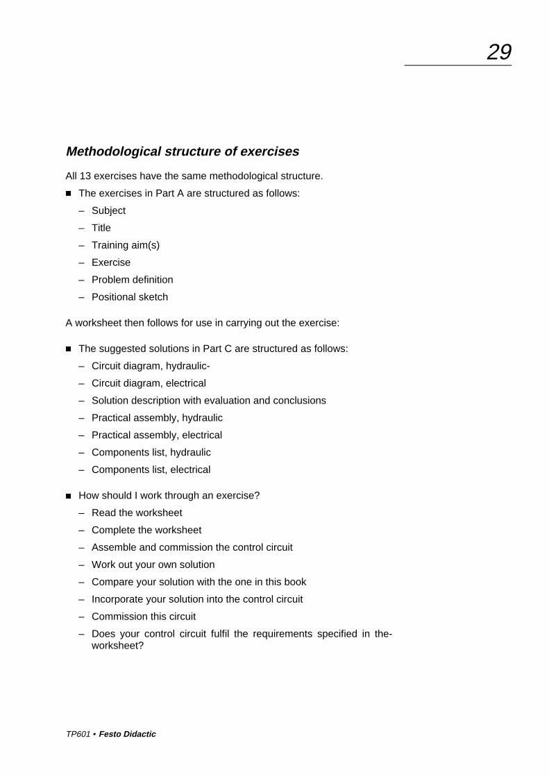
Methodological structure of exercises
All 13 exercises have the same methodological structure.
� The exercises in Part A are structured as follows:
– Subject
– Title
– Training aim(s)
– Exercise
– Problem definition
– Positional sketch
A worksheet then follows for use in carrying out the exercise:
� The suggested solutions in Part C are structured as follows:
– Circuit diagram, hydraulic-
– Circuit diagram, electrical
– Solution description with evaluation and conclusions
– Practical assembly, hydraulic
– Practical assembly, electrical
– Components list, hydraulic
– Components list, electrical
� How should I work through an exercise?
– Read the worksheet
– Complete the worksheet
– Assemble and commission the control circuit
– Work out your own solution
– Compare your solution with the one in this book
– Incorporate your solution into the control circuit
– Commission this circuit
– Does your control circuit fulfil the requirements specified in the-worksheet?

TP601 • Festo Didactic
30
TP601 • Festo Didactic
A-1
Part A – Course
Simple control circuits without limit switches
Exercise 1: Sorting deviceDouble-acting cylinder,directly actuated, manually A-3
Exercise 2: Component selection on conveyor beltDouble-acting cylinder,directly actuated, manually A-13
Exercise 3: Lifting stationSingle-acting cylinder,directly actuated, manually A-23
Exercise 4: Bending deviceDouble-acting cylinder, latching A-29
Exercise 5: Press-fitting deviceDouble-acting cylinder, latching,return stroke using pressure switch A-33
Exercise 6: Stamping machineDouble-acting cylinder, differential circuit A-39
Exercise 7: Door controlDouble-acting cylinder,interlock, INCHING operation A-43

TP601 • Festo Didactic
A-2
Control circuits with limit switches
Exercise 8: Machining unitDifferential circuit,return stroke using limit switch A-49
Exercise 9: Feed for drilling machineRapid-traverse feed circuit,speeds controlled by limit switch A-53
Exercise 10: PressPressure control circuit with limit switchand pressure switch A-59
Exercise 11: Feed devicePressureless pump bypass with limit switch A-63
Control circuits with two actuators
Exercise 12: Assembly devicePressure-dependent sequence control withcylinder and hydraulic motor A-69
Exercise 13: Lifting device for packagesPosition-dependent sequence controlwith two cylinders A-75
We hope you enjoy the designing and practical assembly of the circuits.Understanding hydraulics is fun!

TP601 • Festo Didactic
A-3Exercise 1
Electrohydraulics
Sorting device
� Understanding an directly actuated, manually operated circuit
� Actuation of a double-acting cylinder using a 4/2-way solenoid valve
� Naming the most important components of a double-acting cylinder
� Naming the most important components of a 4/2-way solenoid valve
� Understanding the use of the electrical signal input unit
� Selection of repuired components
� Developing and drawing the hydraulic and electrical circuit diagrams
� Understanding the variants available for mounting components on theprofile plate
� Mounting components in a mounting frame
� Working with hydraulic hose lines
� Connecting up electrical test leads in accordance with a diagram
� Commissioning the control circuit
� Complete the worksheets
� Define the required components
� Draw the hydraulic and electrical circuit diagrams
� Label the connections
� Number the components in the circuit assembly
� Familiarise yourself with the hydraulic and electrical power supplies
� Carry out practical assembly of the hydraulic and electrical controlcircuits
� Commission the control circuit
� Compile the components lists
� Dismantle the control circuit and replace the components in the stor-age tray
Subject
Title
Training aims
Problem definition

TP601 • Festo Didactic
A-4Exercise 1
A sorting device is used to sort heavy steel workpieces.
When a START pushbutton is pressed, the piston rod of a double-actingcylinder pushes the adjacent workpiece off the conveyor belt.When theSTART pushbutton is released, the piston rod returns to ist retractedend position.
Parameter
Only a small number of hydraulic and electrical components should beused.
Exercise
Fig. 1/1:Positional sketch
TP601 • Festo Didactic
A-5Exercise 1
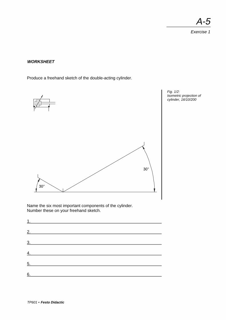
WORKSHEET
Produce a freehand sketch of the double-acting cylinder.
Name the six most important components of the cylinder.Number these on your freehand sketch.
1.
2.
3.
4.
5.
6.
Fig. 1/2:Isometric projection ofcylinder, 16/10/200

TP601 • Festo Didactic
A-6Exercise 1
Produce a freehand sketch of the 4/2-way solenoid valve.
Name five major components of the 4/2-way solenoid valve.Number these on your freehand sketch.
1.
2.
3.
4.
5.
Fig. 1/3:Isometrische Projektion4/2-Wege-Magentventil

TP601 • Festo Didactic
A-7Exercise 1
WORKSHEET
Name five major components of the electrical signal input unit.Number these on the illustration.
1.
2.
3.
4.
5.
Fig. 1/4:Signal input unit (photo)

TP601 • Festo Didactic
A-8Exercise 1
Mark the connection designations on the front panel.
What colour are the 4 mm sockets? Please indicate this.
What is the difference in the function of a pushbutton and a switch?
Fig. 1/5:Signal input unit;
front panel

TP601 • Festo Didactic
A-9Exercise 1
WORKSHEET
Complete the hydraulic circuit diagram.
Complete the list of hydraulic components.
Qty. Description
Hydraulic power pack, 2 l/min
Double-acting cylinder, 16/10/200
Hose line with quick-release coupling, 600 and 1000
Fig. 1/6:Circuit diagram, hydraulic
List ofhydraulic components

TP601 • Festo Didactic
A-10Exercise 1
Complete the electrical circuit diagram.
Complete the list of electrical components.
Qty. Description
Signal input unit, electrical
Cable set, universal with safety plugs
Power supply unit, 24V
Fig. 1/7:Circuit diagram, electrical
List ofelectrical components

TP601 • Festo Didactic
A-11Exercise 1
WORKSHEET
How do you mount the cylinder on the profile plate?
How do you mount the 4/2-way solenoid valve on the profile plate?
Fig. 1/8:Variant B
Fig. 1/9:Variant A

TP601 • Festo Didactic
A-12Exercise 1
How do you mount the electrical signal input unit on the profile plate??
Where else could you mount the electrical signal input unit?
Fig. 1/10:Variant D