
Electrodynamics - GREY COLLEGE SECONDARY
67
Electrodynamics p. 276
Transcript of Electrodynamics - GREY COLLEGE SECONDARY

Electrodynamicsp. 276

Ɛ = -NΔɸ
Δ𝑡
Induced emf
Emf (V)
Amount of windings
Change in magnetic flux

The induced emf in a conductor is directly proportional to the rate of
change in magnetic flux in a conductor.
Faraday’s law

If there is a change in the coupling between the magnetic field and the conductor, an emf is induced. If the
conductor is part of a complete circuit, a current is induced.
Electromagnetic induction

Flemming’s right hand rule

Mechanical energy → Electrical energy
Generators
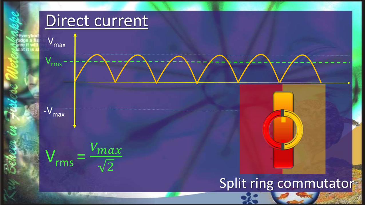
Vmax
-Vmax
Vrms = 𝑉𝑚𝑎𝑥
2
Vrms
Direct current
Split ring commutator

Vmax
-Vmax
N
SVrms = 𝑉𝑚𝑎𝑥
2
Vrms
Alternating current2 slip rings
Root of the mean squared

Imax
-Imax
Irms = 𝐼𝑚𝑎𝑥
2
Irms

Electrical energy →mechanical energy
Electric motor

N S
Electric motorLeft hand motor rule

To change the turn effect:• Increase or decrease the current• Change the amount of turns on the
solenoid• Increase or decrease the magnetic
field
Electric motor

Uses:• Electric drill• Watches• Dentist’s drill
Electric motor

Split ring commutators vs slip rings
Direct current motors vs. alternating current motors

Alternating currentp. 299
The power transferred to heat is: P = I2R.The current should therefor be restricted to a minimum when energy is sent across high voltage cables.
Transformers only works with alternating current

A Step-up transformer is used to increase the voltage, but decrease the current in order to send electricity across high voltage cables.A step-down transformer is used to decrease the voltage and increase the current in order to use the electricity in homes and industries.

Voltage alternates at 50 Hz.

Vmax
-Vmax
N
S

Vmax
-Vmax
N
S

Vmax
-Vmax
N
S

Vmax
-Vmax
N
S

Vmax
-Vmax
N
S

Vmax
-Vmax
N
S

Vmax
-Vmax
N
S

Vmax
-Vmax
N
S

Vmax
-Vmax
N
S

A geyser is labelled 2000W, 230V, 50 Hz.ExampleWhat does 50Hz mean?
50 cycles are completed per second

What is the maximum voltage that this geyser can withstand?
Vrms = 𝑉𝑚𝑎𝑥
2
230V = 𝑉𝑚𝑎𝑥
2
Vmax = 325,27V
A geyser is labelled 2000W, 230V, 50 Hz.Example

Calculate the resistance of the geyser.
Pave = Vrms.Irms =𝑉𝑟𝑚𝑠 2
𝑅
2000 =230 2
𝑅
R = 26,45Ω
A geyser is labelled 2000W, 230V, 50 Hz.Example

Calculate the current in the geyser.
Pave= Vrms.Irms
2000 = 230 × Irms
Irms = 8,70A
A geyser is labelled 2000W, 230V, 50 Hz.Example

A geyser is labelled 2000W, 230V, 50 Hz.
Example
Draw a potential difference against time graph for half a cycle and indicate Vrms
and Vmax on the graph.
Vmax(325,27)
-Vmax
(-325,27)
Vvms (230)
V (V)
t (s)

Exercise 1 (p. 283)2, 10
Exercise 2 (p. 295)5, 8, 9
Exercise 3 (p. 305)6 , 7, 11, 14

2. The following figure shows a typical AC generator.2.1 Name every part of an AC generator and give the function of each

2. The following figure shows a typical AC generator.2.2 Name the basic principle that occurs in an electric generator
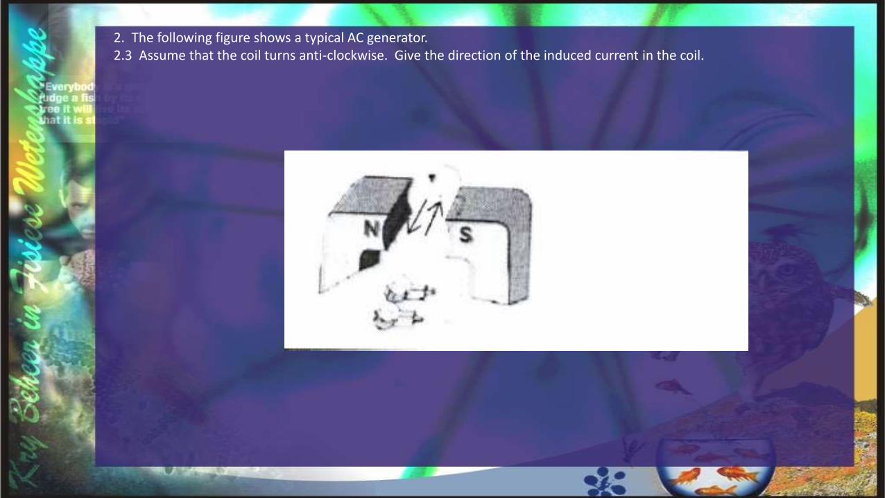
2. The following figure shows a typical AC generator.2.3 Assume that the coil turns anti-clockwise. Give the direction of the induced current in the coil.

2. The following figure shows a typical AC generator.2.4 Name the energy conversion that occurs in an electrical generator.

2. The following figure shows a typical AC generator.2.5 Which rule can be used to determine the direction of the induced current?

2. The following figure shows a typical AC generator.2.6 For each of the following positions of the coil, say whether the induced current in the coil is zero of a maximum and give the direction of the current. Also in each case give a reason for your answer.

2. The following figure shows a typical AC generator.2.7 Sketch a graph of emf versus position of the coil for one full rotation, where the coil originally begins in the horizontal position.

2. The following figure shows a typical AC generator.2.8 Sketch a graph of an induced current versus position of the coil for one full rotation, where the coil originally beginsin the horizontal position.

2. The following figure shows a typical AC generator.2.9 Name three methods to increase the induced emf in an electrical generator. Explain why each factor increases the induced emf.

10. AC-generators differ from DC-generators regarding their construction and type of current that is delivered. The simplified sketch here present a DC-generator.10.1 Which component (P or Q) makes it possible for this generator to deliver DC?

10. AC-generators differ from DC-generators regarding their construction and type of current that is delivered. The simplified sketch here present a DC-generator.10.2 Which structural changes must be made on this generator to change it to a AC-generator?

10. AC-generators differ from DC-generators regarding their construction and type of current that is delivered. The simplified sketch here present a DC-generator.10.3 Alternating current (AC) is generated at power plants.10.3.1 Explain in your own words what alternating current is.

10. AC-generators differ from DC-generators regarding their construction and type of current that is delivered. The simplified sketch here present a DC-generator.10.3 Alternating current (AC) is generated at power plants.10.3.2 Why is it beneficial to work with alternating current?

10. AC-generators differ from DC-generators regarding their construction and type of current that is delivered. The simplified sketch here present a DC-generator.10.4 Explain shortly why Eskom prefers AC over DC for the long distance transmission of electricity.

10. AC-generators differ from DC-generators regarding their construction and type of current that is delivered. The simplified sketch here present a DC-generator.10.5 The diagram below shows a dynamo that is attached to the wheel of a bicycle. When riding the bucyle, the wheel rotates a magnet near the coil.Explain how the current is induced in the coil.

p. 297
5. The following Figure shows a simple direct current motor.5.1 Draw an arrow on the Figure to indicate the direction in which the part FG of the coil will move.

p. 197
5. The following Figure shows a simple direct current motor.5.2 Draw a second arrow on the Figure to indicate the direction of the magnetic field.

p. 197
5. The following Figure shows a simple direct current motor.5.3 Why does the direct current motor's anchor have a coil with many windings, rather than only one winding as shown in the figure.

p. 197
5. The following Figure shows a simple direct current motor.5.4 Explain why the sides DE and FG of the coil, when they are in position, as shown in the figure, will experience a force.

p. 197
5. The following Figure shows a simple direct current motor.5.5 Explain why there is no force on sides FE and DG.

p. 197
5. The following Figure shows a simple direct current motor.5.6 Study the formula and name 5 ways what maximum torque can be exerted on the coil.
τ = NIABsinθ

8. The figure shows a simple electrical motor. 8.1 Name the parts of the motor that are indicated with (1) and (2) in the figure.

8. The figure shows a simple electrical motor. 8.2 What is the function of each of the parts named (1) and (2) in any electrical motor

8. The figure shows a simple electrical motor. 8.3 Name two differences between the electrical motor shown in the Figure and the kind of motor that we get in industrial appliances.

9. The figure shows two electrical machines marked Appliance 1 and Appliance 29.1 What is Appliance 1?

9. The figure shows two electrical machines marked Appliance 1 and Appliance 29.2 What energy-conversion takes place in Appliance 1?

9. The figure shows two electrical machines marked Appliance 1 and Appliance 29.3 What is appliance 2?

9. The figure shows two electrical machines marked Appliance 1 and Appliance 29.4 What energy-conversion takes place in Appliance 2

9. The figure shows two electrical machines marked Appliance 1 and Appliance 29.5 Name one use, one advantage and one disadvantage in Appliance 2.


p. 3056. The form of the wave is a graphic representation of the change in voltage versus time for an alternating current source.6.1 Calculate the frequency at which the alternating current is delivered.6.2 Calculate the effective value (rms) of the voltage.6.3 Calculate the power that is released through the source if it delivers a 5A-rms-current.

7.

11.

14.


![[electrodynamics]-griffiths ans](https://static.fdocuments.in/doc/165x107/55c57e93bb61ebbd5d8b46ae/electrodynamics-griffiths-ans.jpg)


