Electro Mechanical brake
17
A SEMINAR ON ELECTRO-MAGNETIC BRAKE Submitted By: Sushil Lamba 10406EN008 Mechanical IDD Part V
-
Upload
sushil-lamba -
Category
Engineering
-
view
583 -
download
16
Transcript of Electro Mechanical brake
A SEMINAR ON
ELECTRO-MAGNETIC BRAKE
Submitted By: Sushil Lamba
10406EN008
Mechanical IDD
Part V

INTRODUCTION
• Conventional braking systems involves hydraulic assembly operated by electronic
components.
• Need for better fuel economy, ease of vehicle maneuverability and improved safety
systems require new brake technologies.
• The Electro-Mechanical Braking system is different from conventional hydraulic and
electro-hydraulic braking systems.
• The EMB processing components requires high reliabilility electronic components .
• The use of electric brake actuators means additional requirements including motor
control operation within 42-volt power system and high temperatures, and a high
density of electronic components.

ELECTRONIC CONTROL
MODULE
Figure 1: EMB unit setup
Figure 2: Electronic Control Module

MECHANICAL DESIGN ANALYSIS
CONSTITUENT ELEMENTS OF LINEAR
ACTUATOR
• SUN ROLLER
• PLANETARY ROLLERS
• OUTER RING
• CARRIER
• PISTON
• THREADED MEMBER
Figure 3: Schematic of linear actuator


• Planetary rollers are shrink-fitted between sun roller and the fixed outer ring.
• Spiral threading is provided on the outer circumference of each of planetary rollers as well as on the inner circumference of the outer ring.
• While revolving and rotating, the planetary rollers will be axially shifted relative to the outer ring.
• The carrier and piston each support rotation and revolution of the planetary
rollers; then the rotary motion of the sun roller is finally converted into the linear motion of the piston.
• The amount of axial displacement x of the piston relative to the rotary motion of the sun roller can be expressed with the formula (1).
• The amount of axial displacement xBS of the nut on the ball-screw can be expressed with the formula (2).

Efficiency of the EMB
Sun roller supporting bearing
HousingRotation supporting bearing
Revolution
supporting
bearing
Torque:T S
Angular Thrust:FAxial
Assumptions:• The thrust occurring on the piston is uniformly carried by all the
planetary rollers and threads.
• Because of the smaller lead angle( not greater than 5 degrees), the circumferential component of the load occurring on the thread can be ignored.
• No slipping occurs at the contact points between the outer circumference of the sun roller and the outer circumference of each planetary roller and between the inner circumference of the outer ring and the outer circumference of each planetary roller.
• The areas where loss appears to occur are the revolution supporting bearing, rotation-supporting bearing, and sun roller supporting bearing and contact surfaces on threads.
Figure 4: Relation of input and output

• The torque being input from the sun roller causes the piston to
move axially. Then, the efficiency of the linear actuator and
relation between the work input and output can be expressed
with formulas (3) and (4), respectively.
• From the relation with a frictional circle ,
we determine the axial tangential force
Pa and took the resultant force value as
the axial load acting on the sun roller
supporting bearing.Figure 5: Load on sun roller

• On the screw threads between planetary
rollers and outer ring, the Hertz contact ellipse
shifts while the planetary rollers rotate.
• Suppose that each planetary roller moves
along the inner circumference of the outer
ring. Then, the contact ellipse on the screw
thread shifts with the sliding motion that
consists of the tangential displacement U of
the center of ellipse (expressed with the
formula (6)) and the rotational displacement θ
on the center of ellipse (expressed with the
formula (7)).
• From amount of sliding V( x, y) from
formula 8 and normal load from
formula 9, sliding-induced loss Wsc on
screw thread can be expressed using
formula 10
Figure 6: Contact Ellipse
Figure 7: Contact ellipse in thread of screw
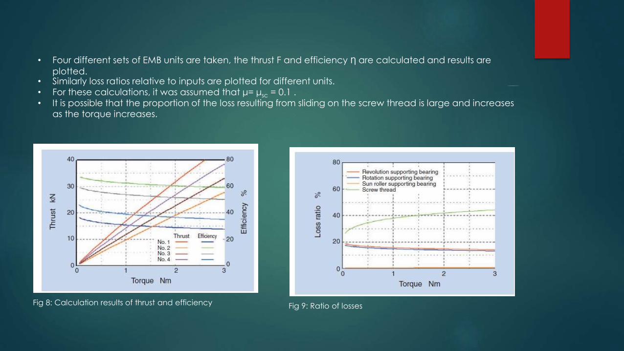
• Four different sets of EMB units are taken, the thrust F and efficiency Ƞ are calculated and results are
plotted.
Fig 8: Calculation results of thrust and efficiency Fig 9: Ratio of losses
• Similarly loss ratios relative to inputs are plotted for different units.• For these calculations, it was assumed that μ= μsc = 0.1 .• It is possible that the proportion of the loss resulting from sliding on the screw thread is large and increases
as the torque increases.

Evaluation for characteristics of linear actuators
• The specifications of the linear actuator units tested are summarized in Table .
• The test results of thrust and efficiency for the units A and B are given in Fig 10 . These results coincide with the result of simulated calculation.
• The relation between the torque and thrust on the linear actuator in one cycle (a duration where the thrust is increased from a zero level to a particular level, and then is decreased to a zero level) is shown in Fig11.
• When the thrust is decreased, a negative torque is necessary on the unit A while a positive torque occurs on the unit B. This is because the sun roller rotates by the thrust and, consequently, its thrust holding function is lost.
Table 1: Specifications of linear actuator
Figure 10: Test results of thrust and
efficiency.

• To address this issue, the relationship is developed between the equivalent lead angle of the linear actuator defined with the formula , efficiency of the linear actuator when it develops 30 kN and availability of its thrust holding function, and this relation is plotted in Fig. 12.
• With a greater equivalent lead angle, the efficiency is better; when the equivalent lead angle is 0.331 deg or greater, the thrust holding function is not available. To sum up, it must be understood that the linear actuator needs to be
designed to have an equivalent lead angle of approximately 0.3 deg so that it can have the thrust holding function.
Figure 11: Reaction between torque and thrust.
Figure 12: Relationship between equivalent lead angle, efficiency and load holding

Evaluation for electromechanical brake units
• It has been evaluated on a test rig and tested as mounted on an actual car while the configuration of the electromechanical brake (EMB) unit is illustrated in Fig. 13 and that of the motor is given in Fig. 14.
• So that the axial length of EMB unit can be shorter, the motor is arranged parallel with the linear actuator and the motor itself is an axial clearance-type motor that has two stators.
• From this motor, the torque is transmitted via a gearing to the sun roller. For convenience of incorporation into an actual car, the linear actuator used is the type B unit which features a compact size.
Figure 13: Prototype EMB unit
Figure 14: Axial Gap Motor

Evaluation about response
• A particular voltage was fed into the motor 0.1 sec. after the beginning of each measuring run, thereby the thrust increase/decrease characteristics were evaluated.
• Under any combination of test conditions, the time-dependent variation in the thrust is nearly constant in the region approximately 10 kN or greater. In the thrust range10 kN or lower, this variation does not appear to be linear.
• It is possible, by applying a greater voltage to the motor, to promote the variation in thrust, in either a thrust increase or decrease mode, to shorten the time needed to reach a targeted load.
• The initial clearance is set to 0.2 mm. When the voltage applied is 12 V, the time needed for a thrust to occur takes approximately 0.1 second while this time span is as short as approximately 0.05 second when the voltage is 20 V.Thus, the size of initial clearance significantly affects the response time.
Figure 15: Response time(increase characteristic)
Figure 16: Response time (decrease characteristic)

Test on actual car
• The prototype EMB unit was installed into each of rear wheels on thetest car.
• It was attempted to brake the car traveling at a speed of approximately 30 km/h, by onlyactuating the EMB units on the rear wheels, and could reliably stop the car. For this test, a 12-V
battery for automotive applications.
Figure 17: Prototype EMB system diagram

Advantages of EMB
• Shorter stopping distances and optimized stability.
• More comfort and safety due to adjustable pedals.
• No pedal vibration in ABS mode.
• Virtually silent.
• Environmentally friendly with no brake fluid.
• Improved crash worthiness.
• Saves space and uses fewer parts.
• Simple assembly.
• Capable of realizing all the required braking and stability functions, such as ABS, EBD, TCS, ESP, BA,
ACC, etc.
• Can easily be networked with future traffic management systems.
• Additional functions, such as an electric parking brake, can easily be integrated.

References
1.Tomohiko ADACHI: The Electronic Stability Control System, Journal of
Society of Automotive Engineers of Japan, Vol.60, No.12 pp.28-33 (2006)
2. Bo Cheng, Tetsuo Taniguchi, Tadashi Hatano, Toshiya Hirose: Effect of
Brake Assistance System in Emergency Situation, Society of Automotive
Engineers of Japan, Lecture Session Preprints, No.20065894
3. A. Palmgren,Ball and Roller Bearing Engineering, 3rd ed., Burbank,
Philadelphia, (1959) 34.