
Electro-Hydraulic / Motorcycle Lift Bench
23
Oct. 2018 Electro-Hydraulic / Motorcycle Lift Bench with Retractable Ramp M-2200IEH-XR Capacity 2,200lbs Installation, Operation & Maintenance Manual
Transcript of Electro-Hydraulic / Motorcycle Lift Bench
Oct. 2018
Electro-Hydraulic / Motorcycle Lift Bench
with Retractable Ramp M-2200IEH-XR Capacity 2,200lbs
Installation, Operation & Maintenance Manual
2 Oct. 2018
M-2200IEH-XR
CONTENTS 1. Safety Information
1.1 Note, Caution and Warning 1.2 Important Information 1.3 Safety Instructions 1.4 Caution and Warning Labels
2. Technical Specifications 2.1 Product Description 2.2 Product Specifications 2.3 Hydraulic Schematic 2.4 Circuit Diagram
3. Preparing and Installation 3.1 Site Selection 3.2 Surface Condition 3.3 Necessary Tools 3.4 Personal Protective Equipment 3.5 Set-Up & Installation
4. Operation 4.1 Operation Instructions
5. Maintenance Instructions
6. Exploded Views & Parts List
7. Trouble Shooting Guide
3 Oct. 2018
M-2200IEH-XR
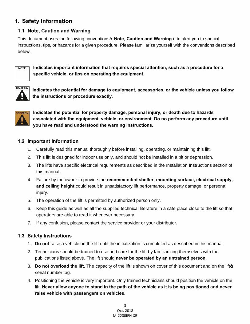
1. Safety Information 1.1 Note, Caution and Warning This document uses the following conventions—Note, Caution and Warning – to alert you to special instructions, tips, or hazards for a given procedure. Please familiarize yourself with the conventions described below.
Indicates important information that requires special attention, such as a procedure for a specific vehicle, or tips on operating the equipment. Indicates the potential for damage to equipment, accessories, or the vehicle unless you follow the instructions or procedure exactly.
Indicates the potential for property damage, personal injury, or death due to hazards associated with the equipment, vehicle, or environment. Do no perform any procedure until you have read and understood the warning instructions.
1.2 Important Information 1. Carefully read this manual thoroughly before installing, operating, or maintaining this lift.
2. This lift is designed for indoor use only, and should not be installed in a pit or depression. 3. The lifts have specific electrical requirements as described in the Installation Instructions section of
this manual.
4. Failure by the owner to provide the recommended shelter, mounting surface, electrical supply, and ceiling height could result in unsatisfactory lift performance, property damage, or personal injury.
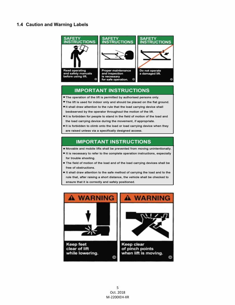
5. The operation of the lift is permitted by authorized person only.
6. Keep this guide as well as all the supplied technical literature in a safe place close to the lift so that operators are able to read it whenever necessary.
7. If any confusion, please contact the service provider or your distributor.
1.3 Safety Instructions 1. Do not raise a vehicle on the lift until the initialization is completed as described in this manual.
2. Technicians should be trained to use and care for the lift by familiarizing themselves with the publications listed above. The lift should never be operated by an untrained person.
3. Do not overload the lift. The capacity of the lift is shown on cover of this document and on the lift’s serial number tag.
4. Positioning the vehicle is very important. Only trained technicians should position the vehicle on the lift. Never allow anyone to stand in the path of the vehicle as it is being positioned and never raise vehicle with passengers on vehicles.
4 Oct. 2018
M-2200IEH-XR
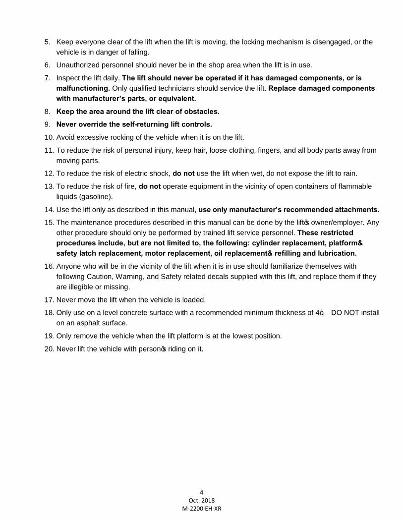
5. Keep everyone clear of the lift when the lift is moving, the locking mechanism is disengaged, or the vehicle is in danger of falling.
6. Unauthorized personnel should never be in the shop area when the lift is in use.
7. Inspect the lift daily. The lift should never be operated if it has damaged components, or is malfunctioning. Only qualified technicians should service the lift. Replace damaged components with manufacturer’s parts, or equivalent.
8. Keep the area around the lift clear of obstacles. 9. Never override the self-returning lift controls. 10. Avoid excessive rocking of the vehicle when it is on the lift.
11. To reduce the risk of personal injury, keep hair, loose clothing, fingers, and all body parts away from moving parts.
12. To reduce the risk of electric shock, do not use the lift when wet, do not expose the lift to rain.
13. To reduce the risk of fire, do not operate equipment in the vicinity of open containers of flammable liquids (gasoline).
14. Use the lift only as described in this manual, use only manufacturer’s recommended attachments. 15. The maintenance procedures described in this manual can be done by the lift’s owner/employer. Any
other procedure should only be performed by trained lift service personnel. These restricted procedures include, but are not limited to, the following: cylinder replacement, platform& safety latch replacement, motor replacement, oil replacement& refilling and lubrication.
16. Anyone who will be in the vicinity of the lift when it is in use should familiarize themselves with following Caution, Warning, and Safety related decals supplied with this lift, and replace them if they are illegible or missing.
17. Never move the lift when the vehicle is loaded.
18. Only use on a level concrete surface with a recommended minimum thickness of 4”. DO NOT install on an asphalt surface.
19. Only remove the vehicle when the lift platform is at the lowest position.
20. Never lift the vehicle with person’s riding on it.
5 Oct. 2018
M-2200IEH-XR
1.4 Caution and Warning Labels
6 Oct. 2018
M-2200IEH-XR
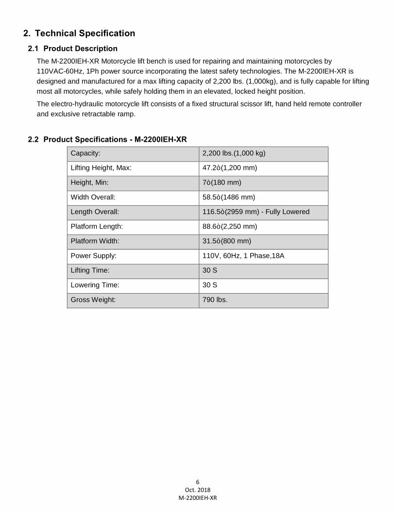
2. Technical Specification 2.1 Product Description
The M-2200IEH-XR Motorcycle lift bench is used for repairing and maintaining motorcycles by 110VAC-60Hz, 1Ph power source incorporating the latest safety technologies. The M-2200IEH-XR is designed and manufactured for a max lifting capacity of 2,200 lbs. (1,000kg), and is fully capable for lifting most all motorcycles, while safely holding them in an elevated, locked height position.
The electro-hydraulic motorcycle lift consists of a fixed structural scissor lift, hand held remote controller and exclusive retractable ramp.
2.2 Product Specifications - M-2200IEH-XR Capacity: 2,200 lbs.(1,000 kg)
Lifting Height, Max: 47.2” (1,200 mm)
Height, Min: 7” (180 mm)
Width Overall: 58.5” (1486 mm)
Length Overall: 116.5” (2959 mm) - Fully Lowered
Platform Length: 88.6” (2,250 mm)
Platform Width: 31.5” (800 mm)
Power Supply: 110V, 60Hz, 1 Phase,18A
Lifting Time: 30 S
Lowering Time: 30 S
Gross Weight: 790 lbs.
7 Oct. 2018
M-2200IEH-XR
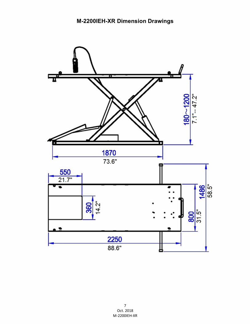
M-2200IEH-XR Dimension Drawings
8 Oct. 2018
M-2200IEH-XR
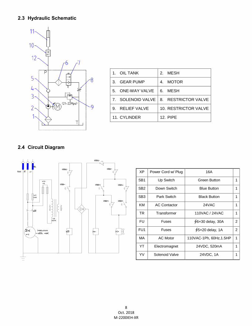
2.3 Hydraulic Schematic
2.4 Circuit Diagram
1. OIL TANK 2. MESH
3. GEAR PUMP 4. MOTOR
5. ONE-WAY VALVE 6. MESH
7. SOLENOID VALVE 8. RESTRICTOR VALVE
9. RELIEF VALVE 10. RESTRICTOR VALVE
11. CYLINDER 12. PIPE
XP Power Cord w/ Plug 16A
SB1 Up Switch Green Button 1
SB2 Down Switch Blue Button 1
SB3 Park Switch Black Button 1
KM AC Contactor 24VAC 1
TR Transformer 110VAC / 24VAC 1
FU Fuses ∮6×30 delay, 30A 2
FU1 Fuses ∮5×20 delay, 1A 2
MA AC Motor 110VAC-1Ph, 60Hz,1.5HP 1
YT Electromagnet 24VDC, 520mA 1
YV Solenoid Valve 24VDC, 1A 1
K MM A1 ~
K MF U
3 0 AY 8 0 L - 2 - 2
1 . 5 H P 1 8 A
4 0 V A
S B 2 S B 2
S B 1
S B 1
S B 3 S B 3
T R
Y VY T
P E N LX P
S B 0
S B 0
F U 11 A
9 Oct. 2018
M-2200IEH-XR
3. Preparing and Installation 3.1 Site Selection The hydraulic motorcycle lift is designed only for indoor use. Application in a room with explosion hazard is not permitted. Setting in a wet place, a car wash bay for instance, is also not recommended. Make sure to check the desired location for possible obstructions such as a low ceiling, overhead lines, adequate working area, access ways, exits, etc.
3.2 Surface Condition The lift should be installed on level ground with a concrete surface free from as many defects as possible to prevent unit from tipping or rocking. Only use on a level concrete surface with a recommended minimum thickness of 4”. DO NOT install on an asphalt type surface.
Failure in accomplish the foundation requirement may cause the lift instability or personal injury. Installing on asphalt, soft clay floor or near the expansion gap is prohibited.
3.3 Necessary Tools Scissors, Screw Driver, Rubber Hammer, Adjustable Spanner Wrench, (Ext.) Snap Ring Pliers and Hex Key Set.
Forklift & Soft Sling Straps also recommended.
3.4 Personal Protective Equipment Always wear proper protective equipment like proper clothing, shoes, gloves & safety glasses, etc.
3.5 Set-Up & Installation
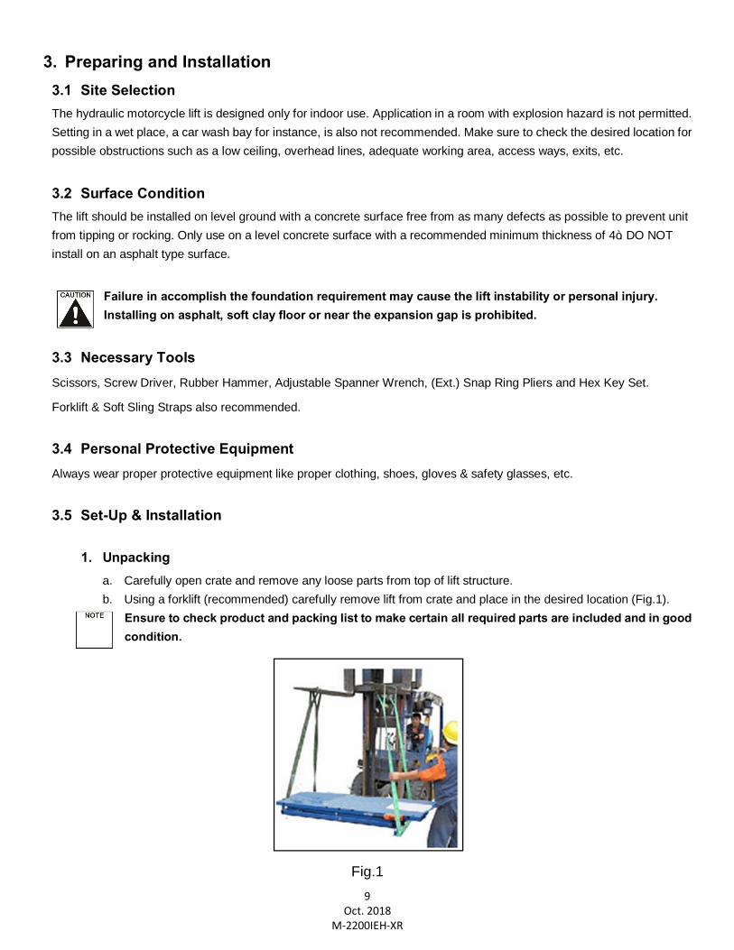
1. Unpacking
a. Carefully open crate and remove any loose parts from top of lift structure. b. Using a forklift (recommended) carefully remove lift from crate and place in the desired location (Fig.1).
Ensure to check product and packing list to make certain all required parts are included and in good condition.
Fig.1
10 Oct. 2018
M-2200IEH-XR
2. Power Connection
Before power connection is made, check your power supply outlet to ensure it’s in accordance with the requirements of the lift.
a. Connect lift’s electrical plug to a 110V-60Hz, 1Ph, 20A power supply outlet. Protection against power surges shall be provided by the user.
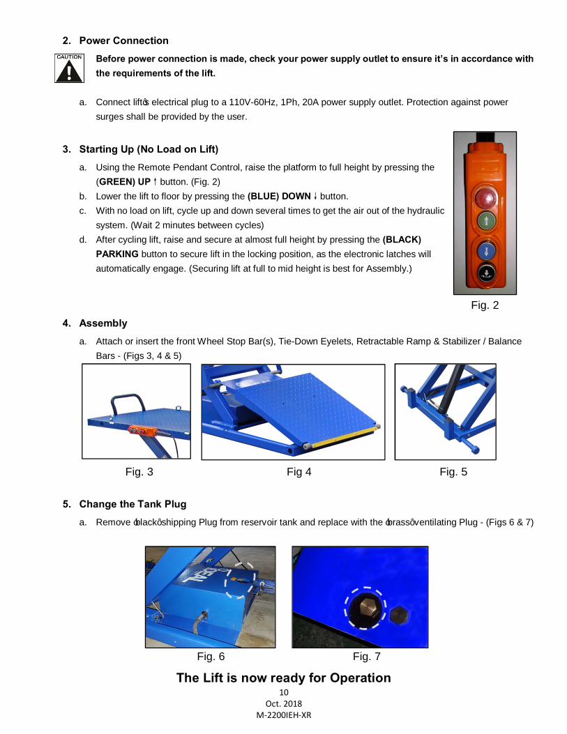
3. Starting Up (No Load on Lift) a. Using the Remote Pendant Control, raise the platform to full height by pressing the
(GREEN) UP↑button. (Fig. 2) b. Lower the lift to floor by pressing the (BLUE) DOWN↓button. c. With no load on lift, cycle up and down several times to get the air out of the hydraulic
system. (Wait 2 minutes between cycles) d. After cycling lift, raise and secure at almost full height by pressing the (BLACK)
PARKING button to secure lift in the locking position, as the electronic latches will automatically engage. (Securing lift at full to mid height is best for Assembly.)
Fig. 2
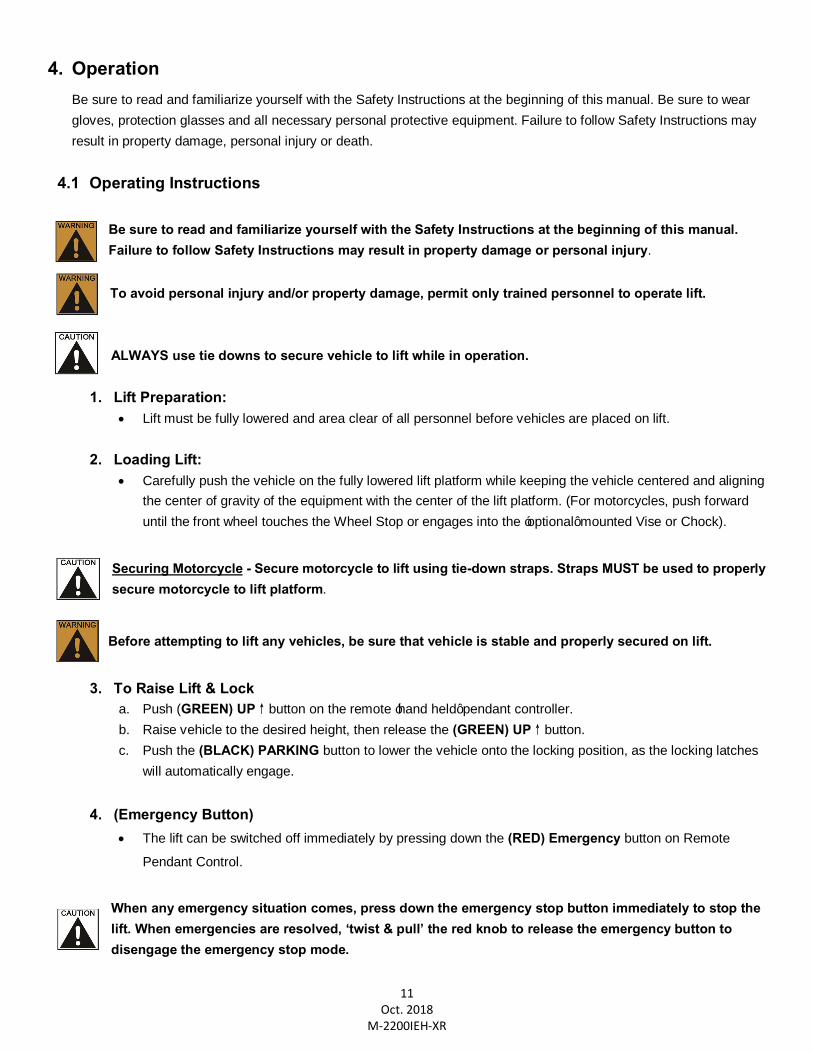
4. Assembly a. Attach or insert the front Wheel Stop Bar(s), Tie-Down Eyelets, Retractable Ramp & Stabilizer / Balance
Bars - (Figs 3, 4 & 5)
Fig. 3 Fig 4 Fig. 5
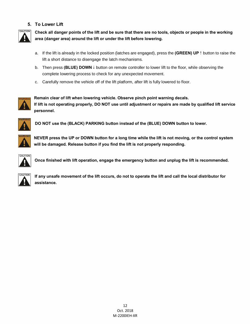
5. Change the Tank Plug a. Remove ‘black’ shipping Plug from reservoir tank and replace with the ‘brass’ ventilating Plug - (Figs 6 & 7)
Fig. 6 Fig. 7
The Lift is now ready for Operation
11 Oct. 2018
M-2200IEH-XR
4. Operation
Be sure to read and familiarize yourself with the Safety Instructions at the beginning of this manual. Be sure to wear gloves, protection glasses and all necessary personal protective equipment. Failure to follow Safety Instructions may result in property damage, personal injury or death.
4.1 Operating Instructions
Be sure to read and familiarize yourself with the Safety Instructions at the beginning of this manual. Failure to follow Safety Instructions may result in property damage or personal injury.
To avoid personal injury and/or property damage, permit only trained personnel to operate lift. ALWAYS use tie downs to secure vehicle to lift while in operation.
1. Lift Preparation: · Lift must be fully lowered and area clear of all personnel before vehicles are placed on lift.
2. Loading Lift:
· Carefully push the vehicle on the fully lowered lift platform while keeping the vehicle centered and aligning the center of gravity of the equipment with the center of the lift platform. (For motorcycles, push forward until the front wheel touches the Wheel Stop or engages into the ‘optional’ mounted Vise or Chock).
Securing Motorcycle - Secure motorcycle to lift using tie-down straps. Straps MUST be used to properly secure motorcycle to lift platform.
Before attempting to lift any vehicles, be sure that vehicle is stable and properly secured on lift.
3. To Raise Lift & Lock
a. Push (GREEN) UP↑button on the remote ‘hand held’ pendant controller. b. Raise vehicle to the desired height, then release the (GREEN) UP↑button. c. Push the (BLACK) PARKING button to lower the vehicle onto the locking position, as the locking latches
will automatically engage.
4. (Emergency Button) · The lift can be switched off immediately by pressing down the (RED) Emergency button on Remote
Pendant Control.
When any emergency situation comes, press down the emergency stop button immediately to stop the lift. When emergencies are resolved, ‘twist & pull’ the red knob to release the emergency button to disengage the emergency stop mode.
12 Oct. 2018
M-2200IEH-XR
5. To Lower Lift
Check all danger points of the lift and be sure that there are no tools, objects or people in the working area (danger area) around the lift or under the lift before lowering.
a. If the lift is already in the locked position (latches are engaged), press the (GREEN) UP↑button to raise the
lift a short distance to disengage the latch mechanisms.
b. Then press (BLUE) DOWN↓button on remote controller to lower lift to the floor, while observing the complete lowering process to check for any unexpected movement.
c. Carefully remove the vehicle off of the lift platform, after lift is fully lowered to floor.
Remain clear of lift when lowering vehicle. Observe pinch point warning decals. If lift is not operating properly, DO NOT use until adjustment or repairs are made by qualified lift service personnel. DO NOT use the (BLACK) PARKING button instead of the (BLUE) DOWN button to lower.
NEVER press the UP or DOWN button for a long time while the lift is not moving, or the control system will be damaged. Release button if you find the lift is not properly responding.
Once finished with lift operation, engage the emergency button and unplug the lift is recommended.
If any unsafe movement of the lift occurs, do not to operate the lift and call the local distributor for assistance.
13 Oct. 2018
M-2200IEH-XR
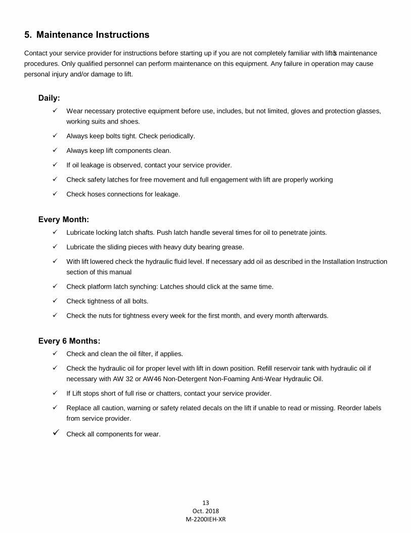
5. Maintenance Instructions
Contact your service provider for instructions before starting up if you are not completely familiar with lift’s maintenance procedures. Only qualified personnel can perform maintenance on this equipment. Any failure in operation may cause personal injury and/or damage to lift.
Daily:
ü Wear necessary protective equipment before use, includes, but not limited, gloves and protection glasses, working suits and shoes.
ü Always keep bolts tight. Check periodically.
ü Always keep lift components clean.
ü If oil leakage is observed, contact your service provider.
ü Check safety latches for free movement and full engagement with lift are properly working
ü Check hoses connections for leakage.
Every Month:
ü Lubricate locking latch shafts. Push latch handle several times for oil to penetrate joints.
ü Lubricate the sliding pieces with heavy duty bearing grease.
ü With lift lowered check the hydraulic fluid level. If necessary add oil as described in the Installation Instruction section of this manual
ü Check platform latch synching: Latches should click at the same time.
ü Check tightness of all bolts.
ü Check the nuts for tightness every week for the first month, and every month afterwards.
Every 6 Months:
ü Check and clean the oil filter, if applies.
ü Check the hydraulic oil for proper level with lift in down position. Refill reservoir tank with hydraulic oil if necessary with AW 32 or AW46 Non-Detergent Non-Foaming Anti-Wear Hydraulic Oil.
ü If Lift stops short of full rise or chatters, contact your service provider.
ü Replace all caution, warning or safety related decals on the lift if unable to read or missing. Reorder labels from service provider.
ü Check all components for wear.
14 Oct. 2018
M-2200IEH-XR
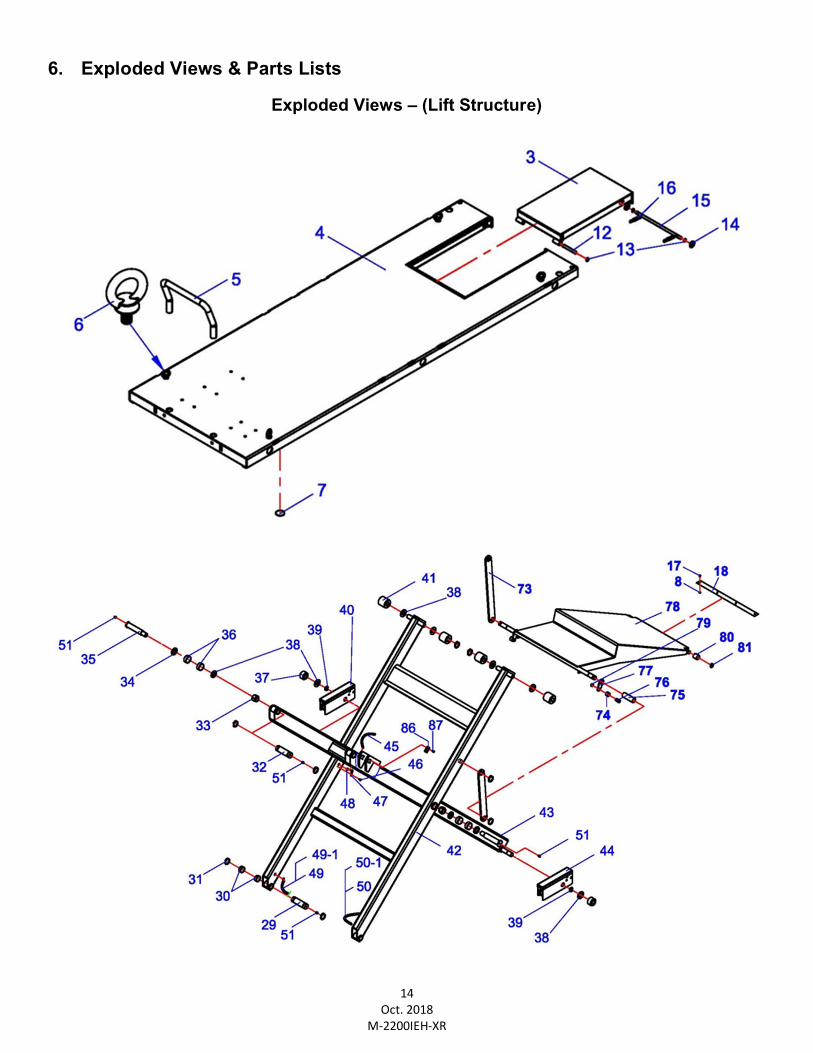
6. Exploded Views & Parts Lists
Exploded Views – (Lift Structure)
15 Oct. 2018
M-2200IEH-XR
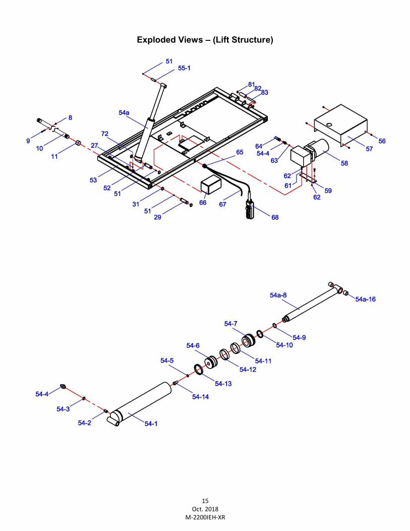
Exploded Views – (Lift Structure)
16 Oct. 2018
M-2200IEH-XR
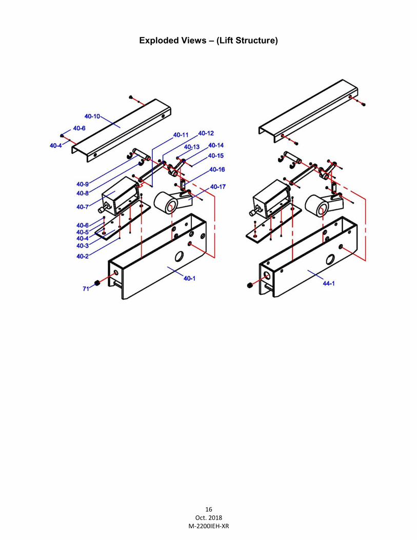
Exploded Views – (Lift Structure)
17 Oct. 2018
M-2200IEH-XR
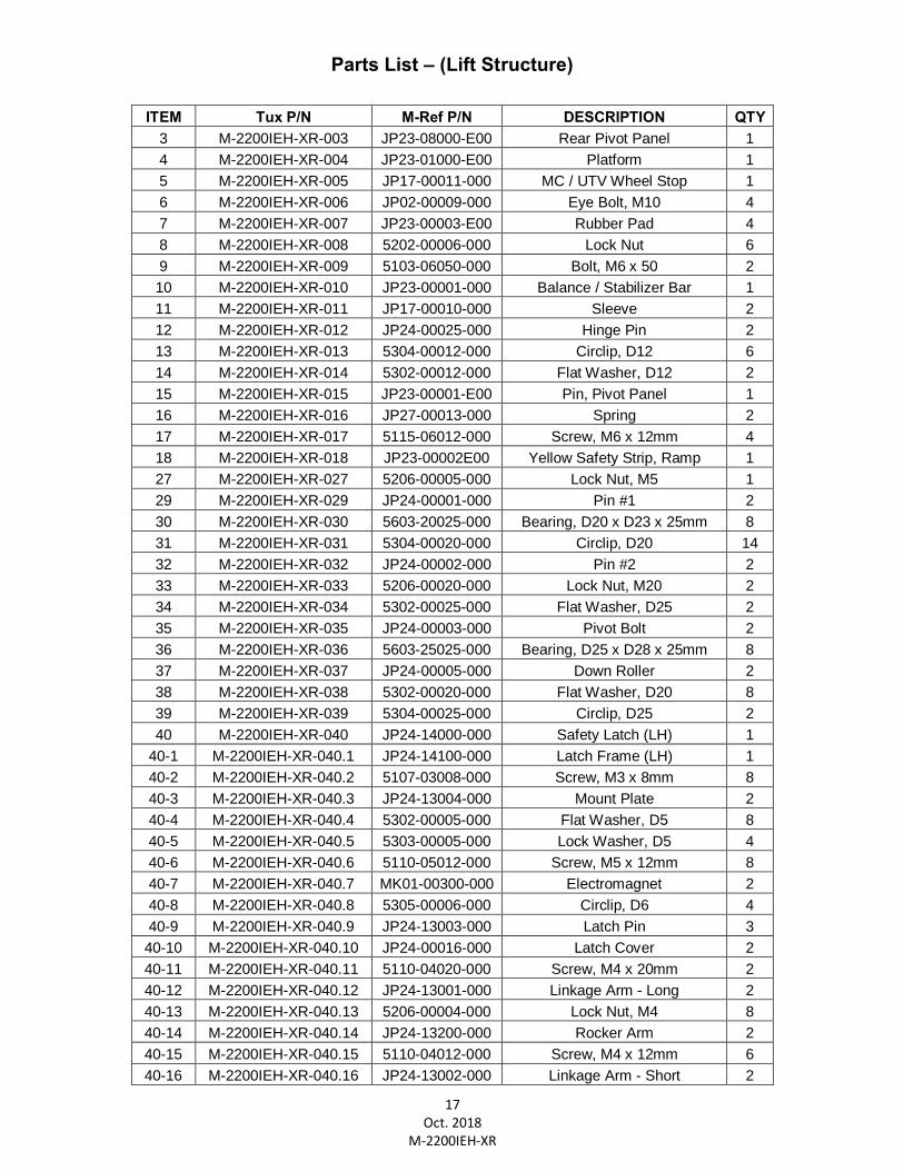
Parts List – (Lift Structure)
ITEM Tux P/N M-Ref P/N DESCRIPTION QTY 3 M-2200IEH-XR-003 JP23-08000-E00 Rear Pivot Panel 1 4 M-2200IEH-XR-004 JP23-01000-E00 Platform 1 5 M-2200IEH-XR-005 JP17-00011-000 MC / UTV Wheel Stop 1 6 M-2200IEH-XR-006 JP02-00009-000 Eye Bolt, M10 4 7 M-2200IEH-XR-007 JP23-00003-E00 Rubber Pad 4 8 M-2200IEH-XR-008 5202-00006-000 Lock Nut 6 9 M-2200IEH-XR-009 5103-06050-000 Bolt, M6 x 50 2 10 M-2200IEH-XR-010 JP23-00001-000 Balance / Stabilizer Bar 1 11 M-2200IEH-XR-011 JP17-00010-000 Sleeve 2 12 M-2200IEH-XR-012 JP24-00025-000 Hinge Pin 2 13 M-2200IEH-XR-013 5304-00012-000 Circlip, D12 6 14 M-2200IEH-XR-014 5302-00012-000 Flat Washer, D12 2 15 M-2200IEH-XR-015 JP23-00001-E00 Pin, Pivot Panel 1 16 M-2200IEH-XR-016 JP27-00013-000 Spring 2 17 M-2200IEH-XR-017 5115-06012-000 Screw, M6 x 12mm 4 18 M-2200IEH-XR-018 JP23-00002E00 Yellow Safety Strip, Ramp 1 27 M-2200IEH-XR-027 5206-00005-000 Lock Nut, M5 1 29 M-2200IEH-XR-029 JP24-00001-000 Pin #1 2 30 M-2200IEH-XR-030 5603-20025-000 Bearing, D20 x D23 x 25mm 8 31 M-2200IEH-XR-031 5304-00020-000 Circlip, D20 14 32 M-2200IEH-XR-032 JP24-00002-000 Pin #2 2 33 M-2200IEH-XR-033 5206-00020-000 Lock Nut, M20 2 34 M-2200IEH-XR-034 5302-00025-000 Flat Washer, D25 2 35 M-2200IEH-XR-035 JP24-00003-000 Pivot Bolt 2 36 M-2200IEH-XR-036 5603-25025-000 Bearing, D25 x D28 x 25mm 8 37 M-2200IEH-XR-037 JP24-00005-000 Down Roller 2 38 M-2200IEH-XR-038 5302-00020-000 Flat Washer, D20 8 39 M-2200IEH-XR-039 5304-00025-000 Circlip, D25 2 40 M-2200IEH-XR-040 JP24-14000-000 Safety Latch (LH) 1
40-1 M-2200IEH-XR-040.1 JP24-14100-000 Latch Frame (LH) 1 40-2 M-2200IEH-XR-040.2 5107-03008-000 Screw, M3 x 8mm 8 40-3 M-2200IEH-XR-040.3 JP24-13004-000 Mount Plate 2 40-4 M-2200IEH-XR-040.4 5302-00005-000 Flat Washer, D5 8 40-5 M-2200IEH-XR-040.5 5303-00005-000 Lock Washer, D5 4 40-6 M-2200IEH-XR-040.6 5110-05012-000 Screw, M5 x 12mm 8 40-7 M-2200IEH-XR-040.7 MK01-00300-000 Electromagnet 2 40-8 M-2200IEH-XR-040.8 5305-00006-000 Circlip, D6 4 40-9 M-2200IEH-XR-040.9 JP24-13003-000 Latch Pin 3
40-10 M-2200IEH-XR-040.10 JP24-00016-000 Latch Cover 2 40-11 M-2200IEH-XR-040.11 5110-04020-000 Screw, M4 x 20mm 2 40-12 M-2200IEH-XR-040.12 JP24-13001-000 Linkage Arm - Long 2 40-13 M-2200IEH-XR-040.13 5206-00004-000 Lock Nut, M4 8 40-14 M-2200IEH-XR-040.14 JP24-13200-000 Rocker Arm 2 40-15 M-2200IEH-XR-040.15 5110-04012-000 Screw, M4 x 12mm 6 40-16 M-2200IEH-XR-040.16 JP24-13002-000 Linkage Arm - Short 2
18 Oct. 2018
M-2200IEH-XR
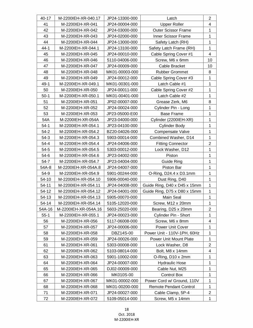
40-17 M-2200IEH-XR-040.17 JP24-13300-000 Latch 2 41 M-2200IEH-XR-041 JP24-00004-000 Upper Roller 4 42 M-2200IEH-XR-042 JP24-03000-000 Outer Scissor Frame 1 43 M-2200IEH-XR-043 JP24-02000-000 Inner Scissor Frame 1 44 M-2200IEH-XR-044 JP24-13000-000 Safety Latch (RH) 1
44-1 M-2200IEH-XR-044.1 JP24-13100-000 Safety Latch Frame (RH) 1 45 M-2200IEH-XR-045 JP24-00010-000 Cable Spring Cover #1 4 46 M-2200IEH-XR-046 5110-04006-000 Screw, M6 x 6mm 10 47 M-2200IEH-XR-047 JP24-00009-000 Cable Bracket 10 48 M-2200IEH-XR-048 MK01-00003-000 Rubber Grommet 8 49 M-2200IEH-XR-049 JP24-00012-000 Cable Spring Cover #3 1
49-1 M-2200IEH-XR-049.1 MK01-00301-000 Latch Cable #1 1 50 M-2200IEH-XR-050 JP24-00011-000 Cable Spring Cover #2 1
50-1 M-2200IEH-XR-050.1 MK01-00401-000 Latch Cable #2 1 51 M-2200IEH-XR-051 JP02-00007-000 Grease Zerk, M6 8 52 M-2200IEH-XR-052 JP24-00024-000 Cylinder Pin - Long 1 53 M-2200IEH-XR-053 JP23-05000-E00 Base Frame 1
54A M-2200IEH-XR-054A JP23-04000-000 Cylinder (2200IEH-XR) 1 54-1 M-2200IEH-XR-054.1 JP23-04100-000 Cylinder Body 1 54-2 M-2200IEH-XR-054.2 BZ20-04026-000 Compensate Valve 1 54-3 M-2200IEH-XR-054.3 5903-00014-000 Combined Washer, D14 1 54-4 M-2200IEH-XR-054.4 JP24-04006-000 Fitting Connector 2 54-5 M-2200IEH-XR-054.5 5303-00012-000 Lock Washer, D12 1 54-6 M-2200IEH-XR-054.6 JP23-04002-000 Piston 1 54-7 M-2200IEH-XR-054.7 JP23-04004-000 Guide Ring 1
54A-8 M-2200IEH-XR-054A.8 JP24-04007-000 Piston Bar 1 54-9 M-2200IEH-XR-054.9 5901-00244-000 O-Ring, D24.4 x D3.1mm 1
54-10 M-2200IEH-XR-054.10 5906-00040-000 Dust Ring, D40 1 54-11 M-2200IEH-XR-054.11 JP24-04008-000 Guide Ring, D40 x D45 x 15mm 1 54-12 M-2200IEH-XR-054.12 JP24-04001-000 Guide Ring, D75 x D80 x 15mm 1 54-13 M-2200IEH-XR-054.13 5905-00070-000 Main Seal 1 54-14 M-2200IEH-XR-054.14 5105-12020-000 Screw, M12 x 20mm 1
54A-16 M-2200IEH-XR-054A.16 5603-25020-000 Bearing, D25 x 20mm 2 55-1 M-2200IEH-XR-055.1 JP24-00023-000 Cylinder Pin - Short 1 56 M-2200IEH-XR-056 5117-06008-000 Screw, M6 x 8mm 4 57 M-2200IEH-XR-057 JP24-00006-000 Power Unit Cover 1 58 M-2200IEH-XR-058 DBZ14S-00 Power Unit - 110V-1PH, 60Hz 1 59 M-2200IEH-XR-059 JP24-00026-000 Power Unit Mount Plate 1 61 M-2200IEH-XR-061 5303-00008-000 Lock Washer, D8 2 62 M-2200IEH-XR-062 5103-08014-000 Bolt, M8 x 14mm 4 63 M-2200IEH-XR-063 5901-10002-000 O-Ring, D10 x 2mm 1 64 M-2200IEH-XR-064 JP24-00007-000 Hydraulic Hose 1 65 M-2200IEH-XR-065 DJ02-00009-000 Cable Nut, M25 1 66 M-2200IEH-XR-066 MK010S-00 Control Box 1 67 M-2200IEH-XR-067 MK01-00002-000 Power Cord w/ Ground, 110V 1 68 M-2200IEH-XR-068 MK01-00200-000 Remote Pendant Control 1 71 M-2200IEH-XR-071 JP24-00027-000 Cable Clamp, 5P-4 2 72 M-2200IEH-XR-072 5109-05014-000 Screw, M5 x 14mm 1
19 Oct. 2018
M-2200IEH-XR
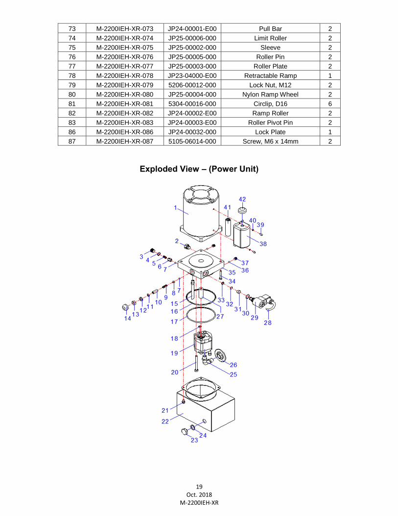
Exploded View – (Power Unit)
73 M-2200IEH-XR-073 JP24-00001-E00 Pull Bar 2 74 M-2200IEH-XR-074 JP25-00006-000 Limit Roller 2 75 M-2200IEH-XR-075 JP25-00002-000 Sleeve 2 76 M-2200IEH-XR-076 JP25-00005-000 Roller Pin 2 77 M-2200IEH-XR-077 JP25-00003-000 Roller Plate 2 78 M-2200IEH-XR-078 JP23-04000-E00 Retractable Ramp 1 79 M-2200IEH-XR-079 5206-00012-000 Lock Nut, M12 2 80 M-2200IEH-XR-080 JP25-00004-000 Nylon Ramp Wheel 2 81 M-2200IEH-XR-081 5304-00016-000 Circlip, D16 6 82 M-2200IEH-XR-082 JP24-00002-E00 Ramp Roller 2 83 M-2200IEH-XR-083 JP24-00003-E00 Roller Pivot Pin 2 86 M-2200IEH-XR-086 JP24-00032-000 Lock Plate 1 87 M-2200IEH-XR-087 5105-06014-000 Screw, M6 x 14mm 2
20 Oct. 2018
M-2200IEH-XR
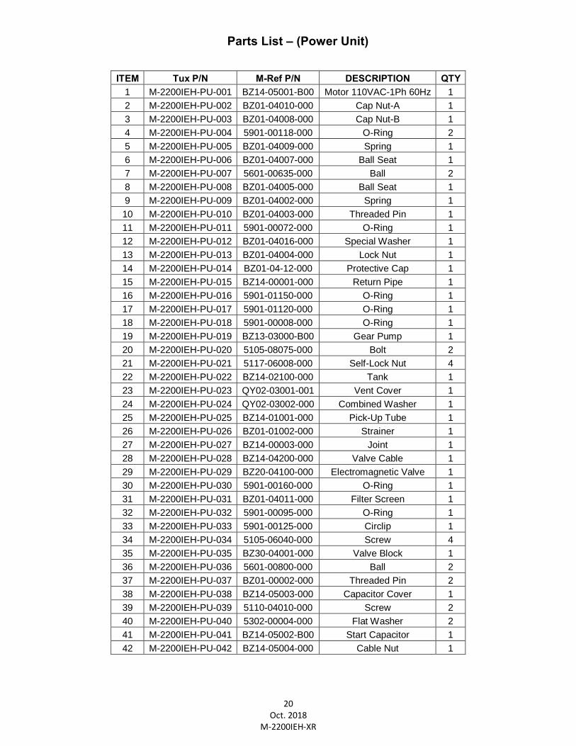
Parts List – (Power Unit)
ITEM Tux P/N M-Ref P/N DESCRIPTION QTY
1 M-2200IEH-PU-001 BZ14-05001-B00 Motor 110VAC-1Ph 60Hz 1 2 M-2200IEH-PU-002 BZ01-04010-000 Cap Nut-A 1 3 M-2200IEH-PU-003 BZ01-04008-000 Cap Nut-B 1 4 M-2200IEH-PU-004 5901-00118-000 O-Ring 2 5 M-2200IEH-PU-005 BZ01-04009-000 Spring 1 6 M-2200IEH-PU-006 BZ01-04007-000 Ball Seat 1 7 M-2200IEH-PU-007 5601-00635-000 Ball 2 8 M-2200IEH-PU-008 BZ01-04005-000 Ball Seat 1 9 M-2200IEH-PU-009 BZ01-04002-000 Spring 1 10 M-2200IEH-PU-010 BZ01-04003-000 Threaded Pin 1 11 M-2200IEH-PU-011 5901-00072-000 O-Ring 1 12 M-2200IEH-PU-012 BZ01-04016-000 Special Washer 1 13 M-2200IEH-PU-013 BZ01-04004-000 Lock Nut 1 14 M-2200IEH-PU-014 BZ01-04-12-000 Protective Cap 1 15 M-2200IEH-PU-015 BZ14-00001-000 Return Pipe 1 16 M-2200IEH-PU-016 5901-01150-000 O-Ring 1 17 M-2200IEH-PU-017 5901-01120-000 O-Ring 1 18 M-2200IEH-PU-018 5901-00008-000 O-Ring 1 19 M-2200IEH-PU-019 BZ13-03000-B00 Gear Pump 1 20 M-2200IEH-PU-020 5105-08075-000 Bolt 2 21 M-2200IEH-PU-021 5117-06008-000 Self-Lock Nut 4 22 M-2200IEH-PU-022 BZ14-02100-000 Tank 1 23 M-2200IEH-PU-023 QY02-03001-001 Vent Cover 1 24 M-2200IEH-PU-024 QY02-03002-000 Combined Washer 1 25 M-2200IEH-PU-025 BZ14-01001-000 Pick-Up Tube 1 26 M-2200IEH-PU-026 BZ01-01002-000 Strainer 1 27 M-2200IEH-PU-027 BZ14-00003-000 Joint 1 28 M-2200IEH-PU-028 BZ14-04200-000 Valve Cable 1 29 M-2200IEH-PU-029 BZ20-04100-000 Electromagnetic Valve 1 30 M-2200IEH-PU-030 5901-00160-000 O-Ring 1 31 M-2200IEH-PU-031 BZ01-04011-000 Filter Screen 1 32 M-2200IEH-PU-032 5901-00095-000 O-Ring 1 33 M-2200IEH-PU-033 5901-00125-000 Circlip 1 34 M-2200IEH-PU-034 5105-06040-000 Screw 4 35 M-2200IEH-PU-035 BZ30-04001-000 Valve Block 1 36 M-2200IEH-PU-036 5601-00800-000 Ball 2 37 M-2200IEH-PU-037 BZ01-00002-000 Threaded Pin 2 38 M-2200IEH-PU-038 BZ14-05003-000 Capacitor Cover 1 39 M-2200IEH-PU-039 5110-04010-000 Screw 2 40 M-2200IEH-PU-040 5302-00004-000 Flat Washer 2 41 M-2200IEH-PU-041 BZ14-05002-B00 Start Capacitor 1 42 M-2200IEH-PU-042 BZ14-05004-000 Cable Nut 1
21 Oct. 2018
M-2200IEH-XR
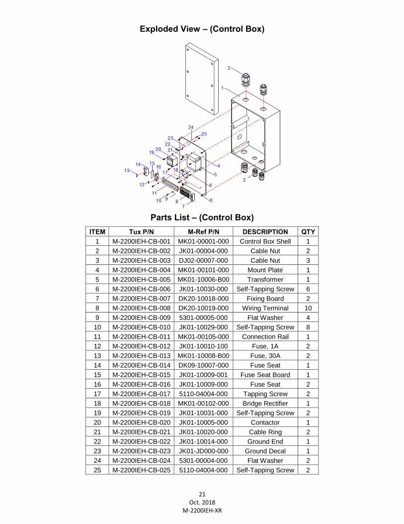
Exploded View – (Control Box)
Parts List – (Control Box)
ITEM Tux P/N M-Ref P/N DESCRIPTION QTY 1 M-2200IEH-CB-001 MK01-00001-000 Control Box Shell 1 2 M-2200IEH-CB-002 JK01-00004-000 Cable Nut 2 3 M-2200IEH-CB-003 DJ02-00007-000 Cable Nut 3 4 M-2200IEH-CB-004 MK01-00101-000 Mount Plate 1 5 M-2200IEH-CB-005 MK01-10006-B00 Transformer 1 6 M-2200IEH-CB-006 JK01-10030-000 Self-Tapping Screw 6 7 M-2200IEH-CB-007 DK20-10018-000 Fixing Board 2 8 M-2200IEH-CB-008 DK20-10019-000 Wiring Terminal 10 9 M-2200IEH-CB-009 5301-00005-000 Flat Washer 4 10 M-2200IEH-CB-010 JK01-10029-000 Self-Tapping Screw 8 11 M-2200IEH-CB-011 MK01-00105-000 Connection Rail 1 12 M-2200IEH-CB-012 JK01-10010-100 Fuse, 1A 2 13 M-2200IEH-CB-013 MK01-10008-B00 Fuse, 30A 2 14 M-2200IEH-CB-014 DK09-10007-000 Fuse Seat 1 15 M-2200IEH-CB-015 JK01-10009-001 Fuse Seat Board 1 16 M-2200IEH-CB-016 JK01-10009-000 Fuse Seat 2 17 M-2200IEH-CB-017 5110-04004-000 Tapping Screw 2 18 M-2200IEH-CB-018 MK01-00102-000 Bridge Rectifier 1 19 M-2200IEH-CB-019 JK01-10031-000 Self-Tapping Screw 2 20 M-2200IEH-CB-020 JK01-10005-000 Contactor 1 21 M-2200IEH-CB-021 JK01-10020-000 Cable Ring 2 22 M-2200IEH-CB-022 JK01-10014-000 Ground End 1 23 M-2200IEH-CB-023 JK01-JD000-000 Ground Decal 1 24 M-2200IEH-CB-024 5301-00004-000 Flat Washer 2 25 M-2200IEH-CB-025 5110-04004-000 Self-Tapping Screw 2
22 Oct. 2018
M-2200IEH-XR
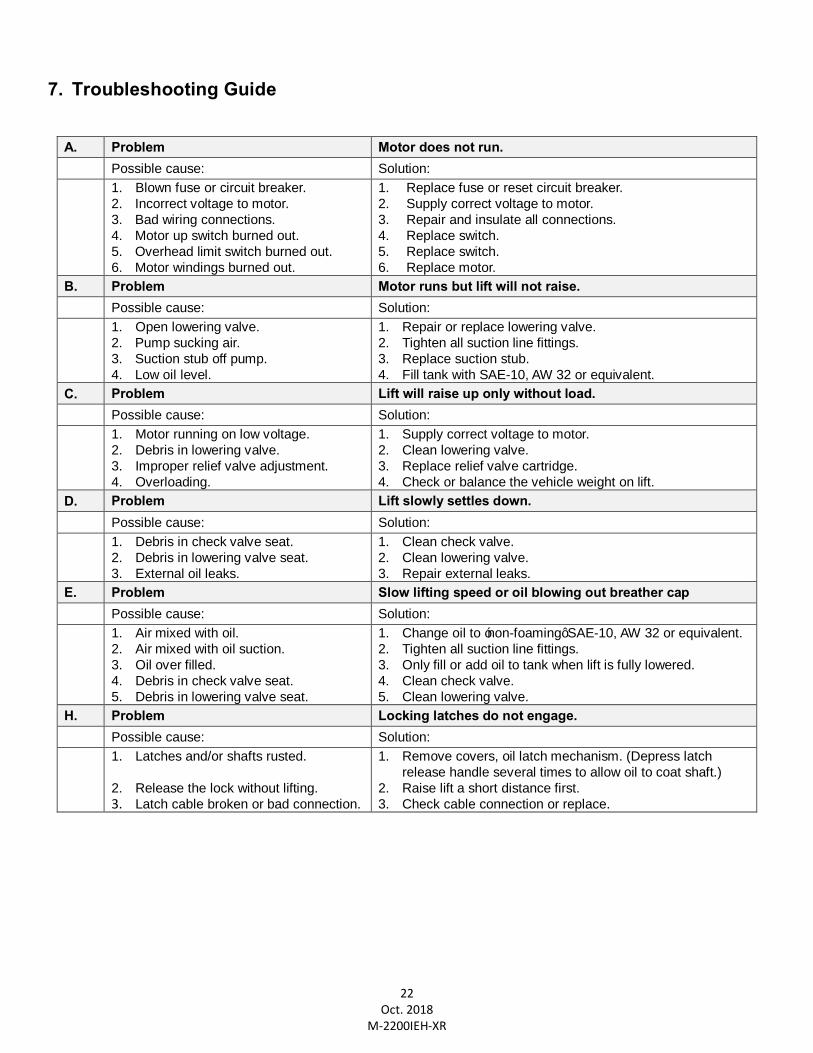
7. Troubleshooting Guide
A. Problem Motor does not run. Possible cause: Solution:
1. Blown fuse or circuit breaker. 2. Incorrect voltage to motor. 3. Bad wiring connections. 4. Motor up switch burned out. 5. Overhead limit switch burned out. 6. Motor windings burned out.
1. Replace fuse or reset circuit breaker. 2. Supply correct voltage to motor. 3. Repair and insulate all connections. 4. Replace switch. 5. Replace switch. 6. Replace motor.
B. Problem Motor runs but lift will not raise. Possible cause: Solution:
1. Open lowering valve. 2. Pump sucking air. 3. Suction stub off pump. 4. Low oil level.
1. Repair or replace lowering valve. 2. Tighten all suction line fittings. 3. Replace suction stub. 4. Fill tank with SAE-10, AW 32 or equivalent.
C. Problem Lift will raise up only without load. Possible cause: Solution:
1. Motor running on low voltage. 2. Debris in lowering valve. 3. Improper relief valve adjustment. 4. Overloading.
1. Supply correct voltage to motor. 2. Clean lowering valve. 3. Replace relief valve cartridge. 4. Check or balance the vehicle weight on lift.
D. Problem Lift slowly settles down. Possible cause: Solution:
1. Debris in check valve seat. 2. Debris in lowering valve seat. 3. External oil leaks.
1. Clean check valve. 2. Clean lowering valve. 3. Repair external leaks.
E. Problem Slow lifting speed or oil blowing out breather cap Possible cause: Solution:
1. Air mixed with oil. 2. Air mixed with oil suction. 3. Oil over filled. 4. Debris in check valve seat. 5. Debris in lowering valve seat.
1. Change oil to ‘non-foaming’ SAE-10, AW 32 or equivalent. 2. Tighten all suction line fittings. 3. Only fill or add oil to tank when lift is fully lowered. 4. Clean check valve. 5. Clean lowering valve.
H. Problem Locking latches do not engage. Possible cause: Solution:
1. Latches and/or shafts rusted.
2. Release the lock without lifting. 3. Latch cable broken or bad connection.
1. Remove covers, oil latch mechanism. (Depress latch release handle several times to allow oil to coat shaft.)
2. Raise lift a short distance first. 3. Check cable connection or replace.
23 Oct. 2018
M-2200IEH-XR
LIMITED WARRANTY Structural Warranty:
The following parts and structural components carry a five year warranty:
Columns Arms Uprights Swivel Pins Legs Carriages Overhead Beam Tracks Cross Rails Top Rail Beam
Limited One-Year Warranty: Tuxedo Distributors, LLC (iDEAL) offers a limited one-year warranty to the original purchaser of Lifts and Wheel Service equipment in the United States and Canada. Tuxedo will replace, without charge, any part found defective in materials or workmanship under normal use, for a period of one year after purchase. The purchaser is responsible for all shipping charges. This warranty does not apply to equipment that has been improperly installed or altered or that has not been operated or maintained according to specifications.
Other Limitations: This warranty does not cover:
1. Parts needed for normal maintenance 2. Wear parts, including but not limited to cables, slider blocks, chains, rubber pads and pulleys 3. Replacement of lift and tire changer cylinders after the first 30 days. A seal kit and installation instructions will
be sent for repairs thereafter. 4. On-site labor
Upon receipt, the customer must visually inspect the equipment for any potential freight damage before signing clear on the shipping receipt. Freight damage is not considered a warranty issue and therefore must be noted for any potential recovery with the shipping company.
The customer is required to notify Tuxedo of any missing parts within 72 hours. Timely notification must be received to be covered under warranty.
Tuxedo will replace any defective part under warranty at no charge as soon as such parts become available from the manufacturer. No guarantee is given as to the immediate availability of replacement parts.
Tuxedo reserves the right to make improvements and/or design changes to its lifts without any obligation to previously sold, assembled or fabricated equipment.
There is no other express warranty on the Tuxedo lifts and this warranty is exclusive of and in lieu of all other warranties, expressed or implied, including all warranties of merchantability and fitness for a particular purpose. To the fullest extent allowed by law, Tuxedo shall not be liable for loss of use, cost of cover, lost profits, inconvenience, lost time, commercial loss or other incidental or consequential damages.
This Limited Warranty is granted to the original purchaser only and is not transferable or assignable.
Some states do not allow exclusion or limitation of consequential damages or how long an implied warranty lasts, so the above limitations and exclusions may not apply. This warranty gives you specific legal rights and you may have other rights, which may vary from state to state.
8320 E Hwy 67, Alvarado, TX 76009
Ph. 817-558-9337 / Fax 817-558-9740