ELECTRICITY & MAGNETISM BY: Arana Rampersad Form: 5D Physics.
28
ELECTRICITY & ELECTRICITY & MAGNETISM MAGNETISM BY: Arana Rampersad BY: Arana Rampersad Form: 5D Form: 5D Physics Physics
-
Upload
oswald-patrick -
Category
Documents
-
view
220 -
download
0
Transcript of ELECTRICITY & MAGNETISM BY: Arana Rampersad Form: 5D Physics.

ELECTRICITY & ELECTRICITY & MAGNETISMMAGNETISM
BY: Arana RampersadBY: Arana Rampersad
Form: 5DForm: 5D
PhysicsPhysics

ELECTRONICSELECTRONICS
RECTIFICATIONRECTIFICATION
RECTIFICATIONRECTIFICATIONWhat is Rectification?What is Rectification?Rectification is the process of converting Rectification is the process of converting
alternating current (a.c.) to direct current alternating current (a.c.) to direct current (d.c.). This is done by a device called a (d.c.). This is done by a device called a rectifier. rectifier.
A device which performs the opposite A device which performs the opposite function (converting DC to AC) is known function (converting DC to AC) is known as an inverter.as an inverter.

RECTIFICATIONRECTIFICATION
FULL WAVE RECTIFICATIONFULL WAVE RECTIFICATIONA full-wave rectifier converts the whole of the input A full-wave rectifier converts the whole of the input
waveform to one of constant polarity (positive or waveform to one of constant polarity (positive or negative) at its output. Full-wave rectification negative) at its output. Full-wave rectification converts both polarities of the input waveform to converts both polarities of the input waveform to DC (direct current), and is more efficient. DC (direct current), and is more efficient.

RECTIFICATIONRECTIFICATION
HALF WAVE RECTIFICATIONHALF WAVE RECTIFICATION In half wave rectification, either the positive or In half wave rectification, either the positive or
negative half of the AC wave is passed, while negative half of the AC wave is passed, while the other half is blocked. Because only one half the other half is blocked. Because only one half of the input waveform reaches the output, it is of the input waveform reaches the output, it is very inefficient if used for power transfer. very inefficient if used for power transfer.

How can a semiconductor diode be How can a semiconductor diode be used in half wave rectificationused in half wave rectification
The two types of semiconductors are: p-type (doped with group The two types of semiconductors are: p-type (doped with group 3 elements) and n-type (doped with group 5 elements.)3 elements) and n-type (doped with group 5 elements.)
A diode is used for rectifying an alternating current, i.e., to A diode is used for rectifying an alternating current, i.e., to obtain from it current which flows in one direction only.obtain from it current which flows in one direction only.
An alternating voltage is applied to the anode by connecting it An alternating voltage is applied to the anode by connecting it to one end of the secondary of a mains transformer, which may to one end of the secondary of a mains transformer, which may be either step-up or step-down according to the voltage be either step-up or step-down according to the voltage required. The cathode heater coil is supplied with current from a required. The cathode heater coil is supplied with current from a separate low-voltage required. The cathode heater coil is separate low-voltage required. The cathode heater coil is supplied with current from a low-voltage secondary winding on supplied with current from a low-voltage secondary winding on the same transformer. The unidirectional current output is the same transformer. The unidirectional current output is obtained from connections made to the other end of the obtained from connections made to the other end of the secondary and the cathode respectively.secondary and the cathode respectively.

How can a semiconductor diode be How can a semiconductor diode be used in half wave rectificationused in half wave rectification
The action is that during that half of the cycle when the anode is The action is that during that half of the cycle when the anode is positive it attracts electrons from the space charge, and hence positive it attracts electrons from the space charge, and hence a current flows in the anode circuit. During the other half of the a current flows in the anode circuit. During the other half of the cycle, when the anode becomes negative, it repels electrons, cycle, when the anode becomes negative, it repels electrons, and consequently no current flows. The output therefore and consequently no current flows. The output therefore consists of a series of impulses or half waves in the same consists of a series of impulses or half waves in the same direction.direction.

Differentiate between direct current Differentiate between direct current from batteries and rectified alternating from batteries and rectified alternating current by a consideration of the V-t current by a consideration of the V-t
graphs for both cases. graphs for both cases.
Rectifying Alternating Current (AC)Rectifying Alternating Current (AC) Alternating Current (AC) flows one way, then the other Alternating Current (AC) flows one way, then the other
way, continually reversing direction. An AC voltage is way, continually reversing direction. An AC voltage is continually changing between positive (+) and continually changing between positive (+) and negative (-). negative (-).
The rate of changing direction is called the The rate of changing direction is called the frequencyfrequency of the AC and it is measured in of the AC and it is measured in hertz (Hz)hertz (Hz) which is the which is the number of forwards-backwards number of forwards-backwards cycles per secondcycles per second. .

Differentiate between direct current Differentiate between direct current from batteries and rectified alternating from batteries and rectified alternating current by a consideration of the V-t current by a consideration of the V-t
graphs for both cases.graphs for both cases. Rectifying Alternating Current (AC)Rectifying Alternating Current (AC)
The diagram below shows a.c. from power supply. The diagram below shows a.c. from power supply. The shape is called a sine wave.The shape is called a sine wave.

Differentiate between direct current Differentiate between direct current from batteries and rectified alternating from batteries and rectified alternating current by a consideration of the V-t current by a consideration of the V-t
graphs for both cases.graphs for both cases. Direct Current (DC) from batteries.Direct Current (DC) from batteries. Direct Current always flows in the same direction, but it may Direct Current always flows in the same direction, but it may
increase and decrease. A DC voltage is always positive (or increase and decrease. A DC voltage is always positive (or always negative), but it may increase and decrease. always negative), but it may increase and decrease.
Electronic circuits normally require a Electronic circuits normally require a steady DCsteady DC supply supply which is constant at one value or a which is constant at one value or a smooth DCsmooth DC supply supply which has a small variation called which has a small variation called rippleripple. .
Cells, batteries and regulated power supplies provide Cells, batteries and regulated power supplies provide steady DCsteady DC which is ideal for electronic circuits. which is ideal for electronic circuits.

Differentiate between direct current Differentiate between direct current from batteries and rectified alternating from batteries and rectified alternating current by a consideration of the V-t current by a consideration of the V-t
graphs for both cases.graphs for both cases. Direct Current (DC) from batteries.Direct Current (DC) from batteries.
The diagram below show steady d.c. from a battery.The diagram below show steady d.c. from a battery.

A simple test to determine whether A simple test to determine whether a semiconductor diode is defective.a semiconductor diode is defective.
A diode is like a one-way electronic valve. Electrons A diode is like a one-way electronic valve. Electrons flow only one way through a diode junction. When a flow only one way through a diode junction. When a source of more positive potential is applied to the source of more positive potential is applied to the anode, the diode will conduct. This is what is called anode, the diode will conduct. This is what is called "forward biasing". If the diode is reversed, current will "forward biasing". If the diode is reversed, current will not pass through the diode. This is what is called not pass through the diode. This is what is called "reverse biasing". The circuit shown below shows the "reverse biasing". The circuit shown below shows the tester light illuminate.tester light illuminate.

A simple test to determine whether A simple test to determine whether a semiconductor diode is defective.a semiconductor diode is defective.
The picture shows the tester The picture shows the tester illuminating with a diode illuminating with a diode forward biased. The cathode forward biased. The cathode (banded end) of the diode is in (banded end) of the diode is in the alligator clip. If you the alligator clip. If you shorten the alligator clip to the shorten the alligator clip to the probe tip you will see a probe tip you will see a brighter illumination than brighter illumination than when connected to the diode. when connected to the diode. This is called a voltage drop This is called a voltage drop across the diode junction. If across the diode junction. If you reverse the diode, the you reverse the diode, the tester will not light. This is a tester will not light. This is a good diode. good diode.
If the light illuminates brightly If the light illuminates brightly both ways, or neither way, both ways, or neither way, the diode is defective. Note the diode is defective. Note that it must light only in one that it must light only in one direction. If the light direction. If the light illuminates very dimly on only illuminates very dimly on only one direction and not the one direction and not the other, the diode may still be other, the diode may still be okay. okay.

ELECTRONICSELECTRONICS
LOGIC GATESLOGIC GATES

LOGIC GATESLOGIC GATES
Logic gatesLogic gates are the fundamental are the fundamental components in digital electronics.components in digital electronics.
There are five basic logic gates: NOT, There are five basic logic gates: NOT, AND, OR, NAND and NOR.AND, OR, NAND and NOR.
A useful tool which analyses the inputs A useful tool which analyses the inputs and outputs of one or more gates by and outputs of one or more gates by logging them in an orderly manner is logging them in an orderly manner is known as a known as a truth tabletruth table..
Symbols for NOT, AND, OR, NAND Symbols for NOT, AND, OR, NAND and NOR logic gates.and NOR logic gates.
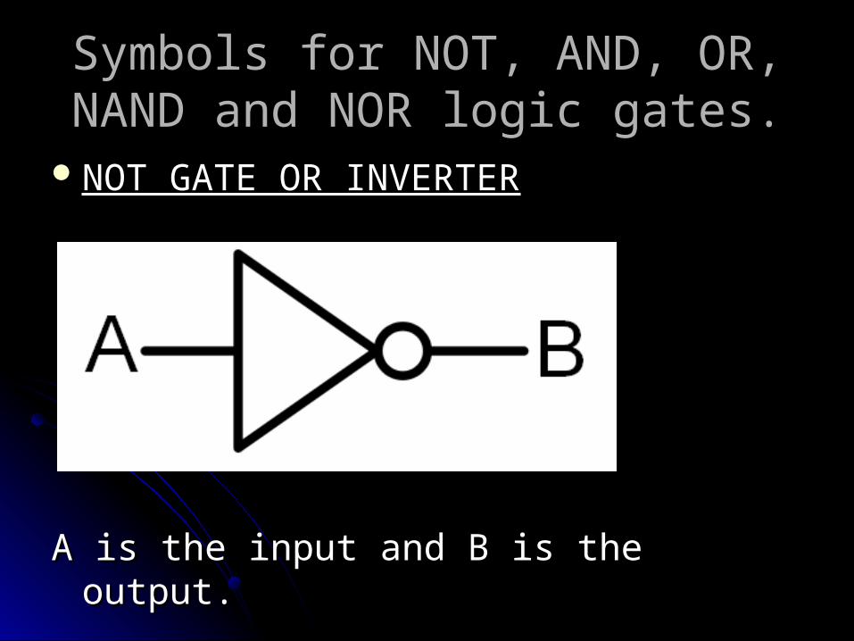
NOT GATE OR INVERTERNOT GATE OR INVERTER
A is the input and B is the output.A is the input and B is the output.

Symbols for NOT, AND, OR, NAND Symbols for NOT, AND, OR, NAND and NOR logic gates.and NOR logic gates.
AND GATEAND GATE
A and B are the inputs and C is the Output.A and B are the inputs and C is the Output.
Symbols for NOT, AND, OR, NAND Symbols for NOT, AND, OR, NAND and NOR logic gates.and NOR logic gates.
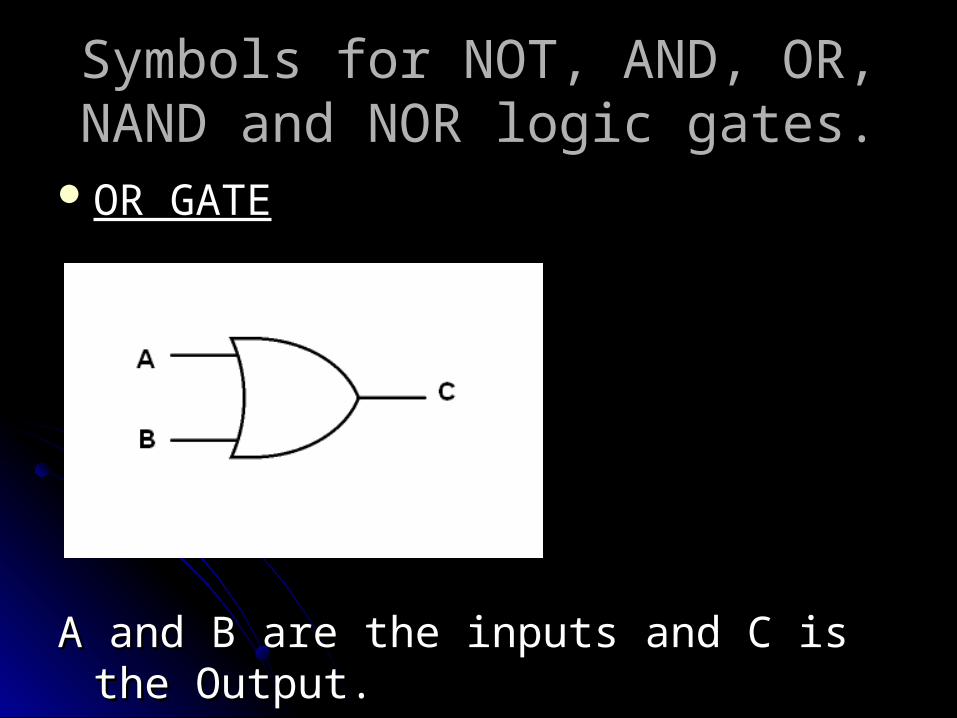
OR GATEOR GATE
A and B are the inputs and C is the Output.A and B are the inputs and C is the Output.

Symbols for NOT, AND, OR, NAND Symbols for NOT, AND, OR, NAND and NOR logic gates.and NOR logic gates.
NAND GATENAND GATE
A and B are the inputs and C is the Output.A and B are the inputs and C is the Output.

Symbols for NOT, AND, OR, NAND Symbols for NOT, AND, OR, NAND and NOR logic gates.and NOR logic gates.
NOR GATENOR GATE
A and B are the inputs and C is the Output.A and B are the inputs and C is the Output.
The Functions of each gate with the The Functions of each gate with the aid of truth tables.aid of truth tables.
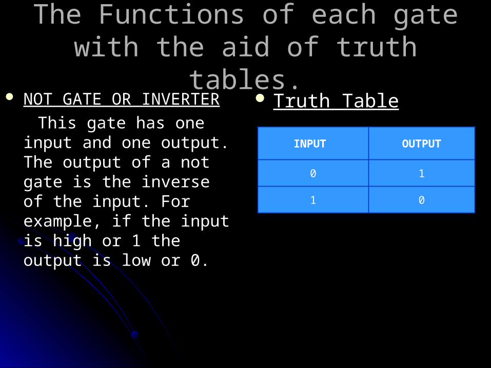
NOT GATE OR INVERTERNOT GATE OR INVERTER
This gate has one input and This gate has one input and one output. The output of a one output. The output of a not gate is the inverse of the not gate is the inverse of the input. For example, if the input. For example, if the input is high or 1 the output input is high or 1 the output is low or 0.is low or 0.
Truth TableTruth Table
INPUT OUTPUT
0 1
1 0

The Functions of each gate with the The Functions of each gate with the aid of truth tables.aid of truth tables.
AND GATEAND GATE
This gate has two or more This gate has two or more inputs and one output. The inputs and one output. The output is high or on only if all output is high or on only if all the inputs are high or on. the inputs are high or on. Under any other conditions Under any other conditions the output is low or off.the output is low or off.
Truth TableTruth Table
INPUT A INPUT B OUTPUT
0 0 0
0 1 0
1 0 0
1 1 1

The Functions of each gate with the The Functions of each gate with the aid of truth tables.aid of truth tables.
OR GATEOR GATE
This gate has two or more This gate has two or more inputs and one output. The inputs and one output. The output is high or on as long output is high or on as long as one or more of the inputs as one or more of the inputs are high or on. Under any are high or on. Under any other conditions the output is other conditions the output is low or off.low or off.
Truth TableTruth Table
INPUT A INPUT B OUTPUT
0 0 0
0 1 1
1 0 1
1 1 1

The Functions of each gate with the The Functions of each gate with the aid of truth tables.aid of truth tables.
NAND GATENAND GATE
This gate has two or more This gate has two or more inputs and one output. The inputs and one output. The output is low or off only if all output is low or off only if all the inputs are high or on. the inputs are high or on. Under any other conditions Under any other conditions the output is high or on.the output is high or on.
Truth TableTruth Table
INPUT A INPUT B OUTPUT
0 0 1
0 1 1
1 0 1
1 1 0

The Functions of each gate with the The Functions of each gate with the aid of truth tables.aid of truth tables.
NOR GATENOR GATE
This gate has two or more This gate has two or more inputs and one output. The inputs and one output. The output is high or on only if all output is high or on only if all the inputs are low or off. the inputs are low or off. Under any other conditions Under any other conditions the output is low or off.the output is low or off.
Truth TableTruth Table
INPUT A INPUT B OUTPUT
0 0 1
0 1 0
1 0 0
1 1 0
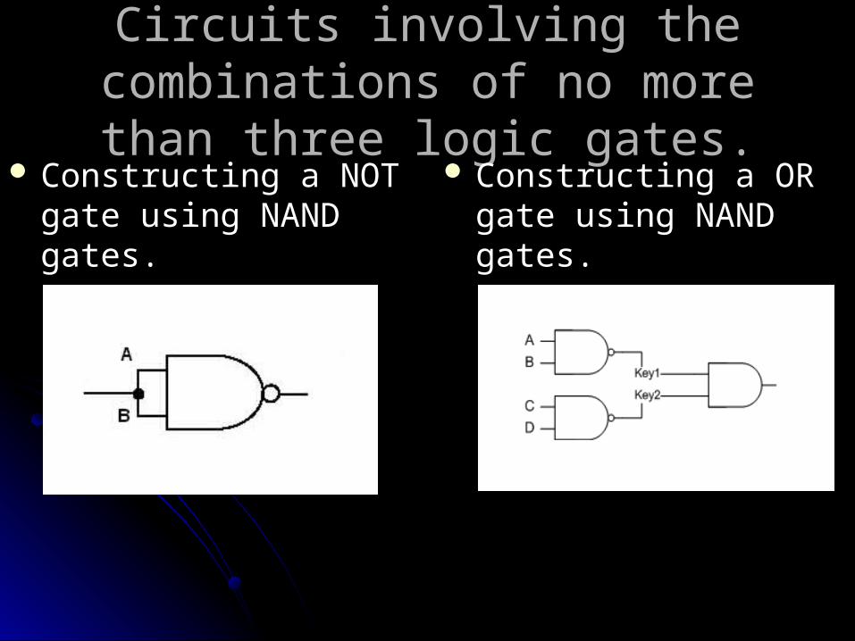
Circuits involving the combinations Circuits involving the combinations of no more than three logic gates.of no more than three logic gates.
Constructing a NOT gate Constructing a NOT gate using NAND gates.using NAND gates.
Constructing a OR gate Constructing a OR gate using NAND gates.using NAND gates.

Circuits involving the combinations Circuits involving the combinations of no more than three logic gates.of no more than three logic gates.
Constructing a AND gate Constructing a AND gate using NAND gates.using NAND gates.
Constructing a NOT gate Constructing a NOT gate using NOR gates.using NOR gates.

Circuits involving the combinations Circuits involving the combinations of no more than three logic gates.of no more than three logic gates.
Constructing a OR gate Constructing a OR gate using NOR gates.using NOR gates.
Constructing a AND gate Constructing a AND gate using NOR gates.using NOR gates.


![e Governance%5B1%5D%5B1%5D[1]](https://static.fdocuments.in/doc/165x107/577d33c21a28ab3a6b8ba828/e-governance5b15d5b15d1.jpg)