Electricity LD
5
Fig. 1 Luminous effects of spontaneous gas discharge at reduced pressure Electricity Electrical conduction in gases Gas discharge at reduced pressure LD Physics Leaflets Investigating spontaneous gas discharge in air as a function of pressure Objects of the experiments Observing spontaneous gas discharge in air as a function of pressure. Measuring the high voltage from the current-limited high-voltage power supply as a function of pressure. Principles Glow discharge is a special form of gas discharge. It takes place spontaneously at low pressures and with a relatively small current density and is accompanied by conspicuous luminous effects. Investigating these effects has yielded basic knowledge on the structure of atoms. In the experiment, a cylindrical glass tube is connected to a vacuum pump and slowly evacuated. A high voltage is applied to the electrodes at the front. At standard pressure no dis- charge occurs. Only at a certain reduced pressure a current begin to flow accompanied by glow light. If the pressure is further reduced, several phases can be observed: first a streamer extends from the anode to the cathode. Then almost the entire space is filled with a luminous column. A surface glow covers the cathode. The column becomes shorter and shorter and disintegrates into several layers whereas the sur- face glow grows. The layering of the luminous zone comes about because the electrons which excite atoms by collision have to cover an accelerating gap after each collisional exci- tation in order to acquire the energy needed for another exci- tation. The distance between the layers thus is a visible measure of the free path. P3.9.2.1 0210-Sel 1
Transcript of Electricity LD

Fig. 1 Luminous effects of spontaneous gas discharge at reduced pressure
ElectricityElectrical conduction in gasesGas discharge at reduced pressure
LDPhysicsLeaflets
Investigatingspontaneous gas discharge in airas a function of pressure
Objects of the experimentsObserving spontaneous gas discharge in air as a function of pressure.
Measuring the high voltage from the current-limited high-voltage power supply as a function of pressure.
Principles
Glow discharge is a special form of gas discharge. It takesplace spontaneously at low pressures and with a relativelysmall current density and is accompanied by conspicuousluminous effects. Investigating these effects has yielded basicknowledge on the structure of atoms.
In the experiment, a cylindrical glass tube is connected to avacuum pump and slowly evacuated. A high voltage is appliedto the electrodes at the front. At standard pressure no dis-charge occurs. Only at a certain reduced pressure a currentbegin to flow accompanied by glow light. If the pressure isfurther reduced, several phases can be observed: first astreamer extends from the anode to the cathode. Then almostthe entire space is filled with a luminous column. A surfaceglow covers the cathode. The column becomes shorter andshorter and disintegrates into several layers whereas the sur-face glow grows. The layering of the luminous zone comesabout because the electrons which excite atoms by collisionhave to cover an accelerating gap after each collisional exci-tation in order to acquire the energy needed for another exci-tation. The distance between the layers thus is a visiblemeasure of the free path.
P3.9.2.1
0210
-Sel
1

Setup
The experimental setup is illustrated in Fig. 2.
– If possible, operate the rotary-vane vacuum pump with anexhaust filter.
– Attach the ball valve with two flanges (a) to the inletmanifold of the rotary-vane vacuum pump and connect thecross over that.
– Mount the variable leak valve (b) and the gauge tube (c) onthe sides of the cross.
– Evenly lubricate the ground socket of the discharge tubewith a thin layer of high-vacuum grease. Press the dis-charge tube on the male ground joint (d) without wedgingor using force, and connect the male ground joint to thecross.
– Check the setup of the vacuum components, and close theclamping rings carefully.
– Connect the gauge tube to the vacuum meter THER-MOVAC.
– Connect the electrodes of the discharge tube with high-voltage cables to the right 5-kV output (I < 2 mA) of thehigh-voltage power supply.
Carrying out the experiment
Remark: for best possible observation of the luminous effects,the experiment should be carried out in a completely darkenedroom.
– Switch the high-voltage power supply on, and set theoutput voltage to U = 5 kV.
– Switch the vacuum meter THERMOVAC on.– Open the variable leak valve completely, the ball valve
partly, and switch the rotary-vane vacuum pump on.– Close the variable leak valve gradually and cautiously so
that that pressure in the discharge tube is reduced moreand more.
– Observe the discharge process while the pressuredecreases. Describe the luminous effects, and write yourobservations down together with the pressure p and thehigh voltage U in each case. For this purpose it is advisableto keep the pressure constant by cautiously controlling thevariable leak valve for a sufficient time period of observa-tion when a luminous effect characteristic of gas dischargeis visible.
– To achieve the ultimate vacuum, open the ball valvecompletely, and close the variable leak valve.
Measuring example
Diagrams of the processes in the discharge tube and of thevoltage in dependence on the pressure (see Figs. 3a-i).
Apparatus1 discharge tube, open . . . . . . . . . . . 554 16
1 rotary-vane vacuum pump, D 2.5 E . . . 378 752
1 small flange DN 10 KFwith male ground joint NS 19/39 . . . . . . 378 0231 cross . . . . . . . . . . . . . . . . . . . 378 0154 centring rings DN 16 KF . . . . . . . . . 378 0454 clamping rings . . . . . . . . . . . . . . 378 0501 variable leak valve . . . . . . . . . . . . 378 7761 ball valve with two flanges DN 16 KF . . 378 777
1 vacuum meter THERMOVAC TM 21 . . . 378 5001 gauge tube TR 211 . . . . . . . . . . . . 378 5011 gauge head cable, 3 m . . . . . . . . . . 378 502
1 high-vacuum grease P, 50 g . . . . . . . 378 701
1 high-voltage power supply, 10 kV . . . . 521 702 high-voltage cables . . . . . . . . . . . . 501 05
additionally recommended:
1 exhaust filter AF 1.8 . . . . . . . . . . . . 378 764
Fig. 2 Experimental setup for investigating spontaneous gas dis-charge in air as a function of pressure
P3.9.2.1 LD Physics Leaflets
2
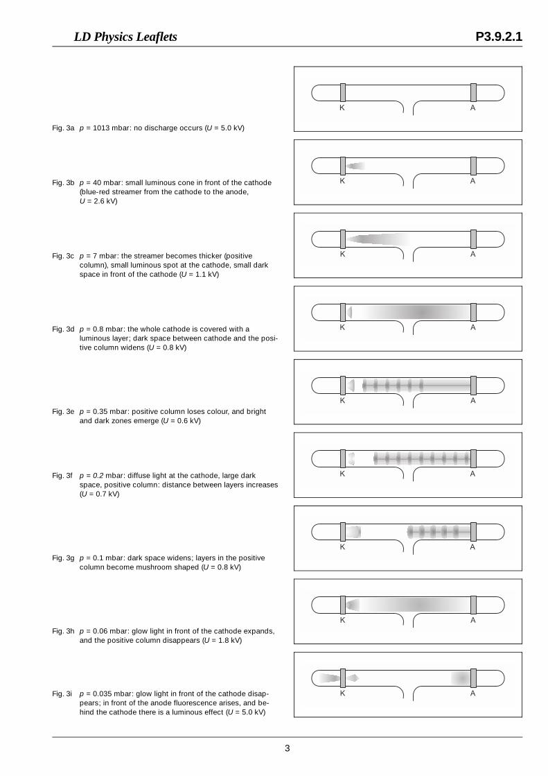
Fig. 3a p = 1013 mbar: no discharge occurs (U = 5.0 kV)
Fig. 3b p = 40 mbar: small luminous cone in front of the cathode(blue-red streamer from the cathode to the anode,U = 2.6 kV)
Fig. 3c p = 7 mbar: the streamer becomes thicker (positivecolumn), small luminous spot at the cathode, small darkspace in front of the cathode (U = 1.1 kV)
Fig. 3d p = 0.8 mbar: the whole cathode is covered with aluminous layer; dark space between cathode and the posi-tive column widens (U = 0.8 kV)
Fig. 3e p = 0.35 mbar: positive column loses colour, and brightand dark zones emerge (U = 0.6 kV)
Fig. 3f p = 0.2 mbar: diffuse light at the cathode, large darkspace, positive column: distance between layers increases(U = 0.7 kV)
Fig. 3g p = 0.1 mbar: dark space widens; layers in the positivecolumn become mushroom shaped (U = 0.8 kV)
Fig. 3h p = 0.06 mbar: glow light in front of the cathode expands,and the positive column disappears (U = 1.8 kV)
Fig. 3i p = 0.035 mbar: glow light in front of the cathode disap-pears; in front of the anode fluorescence arises, and be-hind the cathode there is a luminous effect (U = 5.0 kV)
LD Physics Leaflets P3.9.2.1
3
Evaluation and results
At standard pressure, there are, apart from unchargedmolecules, some negative and positive ions in the dischargetube – produced, e.g., by cosmic radiation – which, accordingto their charge, migrate to the anode or the cathode if anelectric field is applied. However, no discharge occurs. Aspractically no current flows through the discharge tube, thehigh voltage reaches the set value.
By reducing the gas pressure, the free path of the ions isincreased. If the field is sufficiently strong, the velocities ac-quired by the ions are so high that positive ions knock outelectrons from the cathode. These electrons migrate to theanode and, on their way, ionize neutral molecules (impactionization).
If the pressure in the discharge tube decreases, a blue-redluminescent “current thread” appears for some time andpasses into a luminescent effect filling the whole space if thetube is further evacuated (positive column). The voltage breaksdown since the current exceeds the power of the high-voltagepower supply.
If the pressure continues decreasing, the luminescent effectdisintegrates into layers with the shape of discs or mushroomsrespectively. The distance between these layers increases. Theluminescent effect itself becomes weaker.
In front of the cathode, a dark space appears. On the cathodea blue light spot arises.
Eventually this luminescent effect disappears. The glass sur-face begins to fluoresce. Behind the anode a green fluorescentspot is seen which is caused by the cathode rays. At the otherend of the tube, behind the cathode, canal rays are observed(positive gas ions).
While the luminescent effect in the tube disappears, the volt-age gradually assumes its initial value since the current throughthe discharge tube decreases.
The electrons acquire the kinetic energy necessary for impactionization by passing a certain path length (up to the darkspace) in the electric field.
Impact ionization causes the molecules to light up.
The surface glow directly on the cathode is caused by positiveions impinging on the surface.
In the positive column, positive as well as negative ions moveat high velocities into different directions. This gives rise to newexcitations, but hardly to recombination.
If the positive column is made up of layers, the energy of theelectrons in such a layer is sufficient for impact ionization. Theenergy loss has to be compensated by another accelerationbefore the next luminescent layer can be formed.
LD DIDACTIC GmbH ⋅ Leyboldstrasse 1 ⋅ D-50354 Hürth ⋅ Phone (02233) 604-0 ⋅ Telefax (02233) 604-222 ⋅ E-mail: [email protected]© by LD DIDACTIC GmbH Printed in the Federal Republic of Germany
Technical alterations reserved
P3.9.2.1 LD Physics Leaflets