Electricity from a European onshore wind farm using SG 5.0 ...
29
Environmental Product Declaration according to ISO 14025 PCR 2007:08 - Electricity, steam, and hot water generation & distribution - Version 4.0 The International EPD® System Version 1.0 Publication date 2020-07-24 Valid until 2025-07-24 Reg. Number S-P-02157 Geographical validity Europe Electricity from a European onshore wind farm using SG 5.0-145 wind turbines
Transcript of Electricity from a European onshore wind farm using SG 5.0 ...

Environmental Product Declaration according to ISO 14025
PCR 2007:08 - Electricity, steam, and hot water generation & distribution - Version 4.0
The International EPD® System
Version 1.0
Publication date 2020-07-24
Valid until 2025-07-24
Reg. Number S-P-02157
Geographical validity Europe
Electricity from a European
onshore wind farm using
SG 5.0-145 wind turbines
Pag 2 de 29
Contents
1. Introduction .................................................................................................................... 4
1.1. Functional unit ......................................................................................................... 4
1.2. Environmental Declaration and the EPD system ..................................................... 5
2. The company and the product ........................................................................................ 6
2.1. Siemens Gamesa Renewable Energy ..................................................................... 6
2.2. Product system description ..................................................................................... 7
3. Environmental performance based on LCA ...................................................................10
3.1. Life cycle assessment methodology .......................................................................10
3.2. System boundaries and data sources ....................................................................10
3.3. Eco-profile ..............................................................................................................18
3.4. Hot spot analysis and conclusions ..........................................................................21
4. Additional environmental impact ....................................................................................22
4.1. Biodiversity protection ............................................................................................22
4.2. Land use ................................................................................................................23
4.3. Environmental risks ................................................................................................24
4.4. Electromagnetic fields ............................................................................................24
4.5. Noise ......................................................................................................................25
4.6. Visual impact ..........................................................................................................26
5. Certification body and mandatory statements ................................................................26
5.1. Information from the certification body ....................................................................26
5.2. Mandatory statements ............................................................................................26
5.3. Programme and verification information .................................................................28
6. Links and references .....................................................................................................29
Pag 3 de 29
Acronyms and abbreviations
AEP Annual Energy Production
BoM Bill of Materials
B2B Business to Business
B2C Business to consumer
EPD Environmental Product Declaration
GPI General Programme Instructions
HSE Health, Safety & Environment
IUCN International Union for Conservation of Nature
PCR Product Category Rules
CPC Central Product Classification
IEC International Electro technical Commission
ISO International Organization for Standardization
LCA Life Cycle Assessment
LCI Life Cycle Inventory
LCIA Life Cycle Impact Assessment
LCoE Levelized cost of energy
MW Megawatt
WTG Wind Turbine Generator
Pag 4 de 29
1. Introduction
1.1. Functional unit
This document represents the certified Environmental Product Declaration (EPD), of the electricity
generated through an Onshore wind farm of SG 5.0-145 wind turbine generators, located in an European
scenario and operating under medium wind conditions (IEC II wind class).
Siemens Gamesa is dedicated to both the design and the manufacturing of its wind turbines as well as
to the installation commissioning and maintenance of the final product at the wind farm. Therefore, the
company is fully aware of the entire life cycle of their products.
The functional unit, to which all outcomes are referred to is:
A total reference flow of 3,450,246.927 MWh has been used to refer all the inputs and outputs of the
system to 1 single kWh. This reference flow represents the whole net electricity generation expected for
8 SG 5.0-145 WTG under medium wind conditions during its service life, which has been set to 20 years.
Siemens Gamesa is able to supply different kind of towers, seeking a right placement of the rotor at the
height which optimizes the energy harvested. The baseline scenario includes 102.5 meters high towers.
Wind energy is the most reliable and effective renewable energy to meet the growing electricity
demand1, with the foreseeable depletion of the non-renewable traditional energy resources.
Furthermore, it is a guarantee of competitiveness, because in most countries is responsible for the
lowering price of the energy pool.
Although having common features with other renewable energy sources -avoids CO2 emissions, it is an
inexhaustible resource and reduces the energy vulnerability of countries– its industrial character and
maturity, with a developed technological learning curve, allows achieving very competitive market prices.
Wind energy will be the leading technology in transforming the global electricity supply structure towards
a truly sustainable energy future based on indigenous, non-polluting and competitive renewable
technologies.
1 https://ec.europa.eu/eurostat/statistics-explained/index.php?title=Renewable_energy_statistics
Functional unit
1 kWh net of electricity generated through an onshore wind farm of Siemens Gamesa SG 5.0-145
wind turbine generators, located in a European scenario and operating under medium wind
conditions (IEC II), and thereafter distributed to a 132 kV European electrical grid.
Pag 5 de 29
1.2. Environmental Declaration and the EPD system
An environmental product declaration is defined in ISO 14025 as the quantification of environmental
data for a product with categories and parameters specified in the ISO 14040 standard series, but not
excluding additional environmental information.
The international EPD® system (Environdec) has as main goal, the ambition to help and support
organizations to communicate the environmental performance of their products (goods and services) in
a credible and understandable manner.
Therefore, it offers a complete program for any organization interested in developing and communicating
EPDs according to ISO 14025, also supporting other EPD programmes (i.e. national, sectoral, etc.) in
seeking cooperation and harmonization and helping organizations to broaden the use of environmental
claims on the international market.
Environmental Product Declarations add a new dimension to the market, offering information on the
environmental performance of products and services. The use of EPDs, leads to a number of benefits
for organizations that develop declarations of their own products as well as for those who make use of
the information contained in these Environmental Product Declarations.
This EPD has been made in accordance with the standards of the International EPD Consortium.
Environdec, is a system for international use of type III Environmental Declarations, according to ISO
14025. The international EPD® system and its applications are described in the General Program
Instructions (GPI).
The documents on which this EPD is based are, in order of relevance:
• Product Category Rules 2007:08. Electricity, steam, and hot water generation & distribution.
Version 4.0
• General Programme Instructions for Environmental Product Declarations, Ver. 3.01;
• ISO 14025:2010 - Type III environmental declarations;
• ISO 14040:2006 and ISO 14044:2006 on Life Cycle Assessment (LCA).
This EPD contains a LCA-based environmental behavior statement. It also contains additional
environmental information, in accordance with the corresponding PCR 2007:08 - Electricity, steam, and
hot water generation & distribution - Version 4.0:
• Information on the biodiversity protection;
• Information on land use and land cover classification in Europe;
• Information on environmental risks;
• Information on electromagnetic field generation;
• Information on the product noise;
• Information about the visual impact of the wind farm.

Pag 6 de 29
2. The company and the product
2.1. Siemens Gamesa Renewable Energy
Siemens Gamesa is a leading supplier of wind power solutions to customers all over the globe. A key
player and innovative pioneer in the renewable energy sector, we have installed products and
technology in more than 90 countries, with a total capacity base of over 89.5 GW installed globally and
23,000 employees.
Siemens Gamesa´s end-to-end value chain expertise encompasses onshore and offshore wind turbine
design, manufacturing, installation as well as cutting-edge service solutions.
Siemens Gamesa business management system, is certified according to the following international
standards:
• ISO 14001:2015 - Environmental management systems;
• ISO 14006:2011 - Environmental management systems. Guidelines for incorporating eco-
design:
Onshore
Siemens Gamesa Onshore offers an extensive range of wind turbine technologies to cover all wind
classes and site conditions around the world. Continuous innovation, a dedication to technological
excellence and solutions adapted to customer needs are the pillars of our portfolio, setting the
foundation for Siemens Gamesa as a benchmark technologist. This is backed by validated and
recognized products, as well as by more than 35 years of experience and over 76.9 GW installed
across the globe.
Offshore
Siemens Gamesa Offshore is the most experienced player in offshore wind; pioneering the industry
when installing the world’s first offshore wind power plant, Vindeby in Denmark, in 1991. Since then,
we have successfully installed approximately 3,000 offshore wind turbines with a combined
capacity of more than 11.5 GW. These turbines have been installed in Denmark, UK, Germany,
Norway, Sweden, Finland, The Netherlands, China, and Taiwan.
Services
Siemens Gamesa has a proven track record of excellence in operation and maintenance.
Leveraging scale and global reach, we offer a flexible service portfolio that can be tailored to our
customers’ diverse operating models. We also provide advanced diagnostics and digitalization
capabilities, as well as customized offshore services.
Verified eco-designed wind turbines
• SG 114 - 2.1 MW
• SG 114 - 2.625 MW
• SG 126 - 2.625 MW
• SG 132 - 3.465 MW

Pag 7 de 29
• ISO 14064:2006 - Greenhouse gases;
• ISO 9001:2015 - Quality management systems;
• OHSAS 18001:2007 - Occupational health and safety management systems.
2.2. Product system description
The baseline system under study is an European onshore wind farm using SG 5.0-145 wind turbines
with 102.5-meter towers. Since Siemens Gamesa started the LCA study, it was found interesting to
extrapolate the results, as far as possible, to a test case of a European wind farm and not only to a
specific site. The reason pursued, is to make the information extracted from this report useful to a wider
audience. To achieve this goal, it has become necessary to create a generic wind farm model,
representing a Siemens Gamesa European average client.
2.2.1. The European SG 5.0-145 wind site
The differences between the environmental impacts caused by the commissioning of various wind farms
rely primarily on two variables, the location and the size of the site. The location of the wind farm is
directly related to the environmental impact caused in the product distribution stage. The farther the
wind farm is from the production centers, the more logistics needed.
To determine the geographical location of an average Siemens Gamesa 5.0 MW European wind farm,
an analysis has been performed including the location of all the WTGs with a nominal power over 3.0
MW which have been sold by Siemens Gamesa during the last 5 years (2014-2018). Starting from that
information, 6 different European countries have been considered, covering a 79.1% of the total installed
power in Europe. The following table, contains the 6 selected locations including their relative
representativeness within the LCA and the number of installed machines in the virtual site.
Country Representativeness Nº
WTG
Reference wind farm Area
Sweden 26.4%
8
Sidensjö Västernorrland
UK 21.3% Lochluichart Higland – Scotland
Ireland 17.1% Mount Lucas Offaly
Germany 17.0% Süderlügum Schleswig-Holstein
France 10.4% Les Gourlus Marne
Denmark 7.8%
Dostrup Mariagerfjord -
Nordjylland Table 1: Country representativeness and reference locations selected for the European average wind farm
The countries analyzed are Sweden, UK, Ireland, Germany, France and Denmark. These 6 countries
are considered representative of the European situation of Siemens Gamesa over 3.0 MW clients. For
each of these countries, one specific wind farm has been selected as geographical reference.
Regarding the size of the wind farm, the average size of a wind site in Europe has been calculated
dividing the total installed power between the total number of windfarms, and rounding the number up
to 8 wind turbines. Therefore, the installed power considered for the European average wind farm is set
Pag 8 de 29
to 40 MW. When modelling the infrastructures shared by many wind turbines (i.e. transformer substation,
internal wiring, connection infrastructure to the electrical network, road conditioning to allow access to
machinery…), this average wind farm size of 40 MW installed has been used to reference all the values.
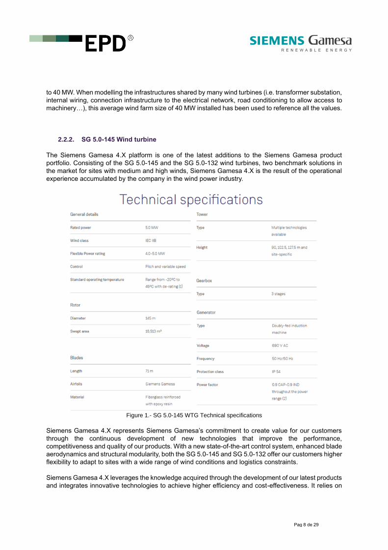
2.2.2. SG 5.0-145 Wind turbine
The Siemens Gamesa 4.X platform is one of the latest additions to the Siemens Gamesa product
portfolio. Consisting of the SG 5.0-145 and the SG 5.0-132 wind turbines, two benchmark solutions in
the market for sites with medium and high winds, Siemens Gamesa 4.X is the result of the operational
experience accumulated by the company in the wind power industry.
Figure 1.- SG 5.0-145 WTG Technical specifications
Siemens Gamesa 4.X represents Siemens Gamesa’s commitment to create value for our customers
through the continuous development of new technologies that improve the performance,
competitiveness and quality of our products. With a new state-of-the-art control system, enhanced blade
aerodynamics and structural modularity, both the SG 5.0-145 and SG 5.0-132 offer our customers higher
flexibility to adapt to sites with a wide range of wind conditions and logistics constraints.
Siemens Gamesa 4.X leverages the knowledge acquired through the development of our latest products
and integrates innovative technologies to achieve higher efficiency and cost-effectiveness. It relies on
Pag 9 de 29
proven concepts with extensive track record in the market, such as the combination of a three-stage
gearbox (two planetary and one parallel) and a doubly-fed induction generator, which offer the higher
levels of reliability. In addition to this, the inclusion of an optional premium converter allows us to comply
with the most demanding grid connection requirements.
With over 30% increase in AEP over previous solutions from the Siemens Gamesa 3.X platform, the SG
5.0-145 and SG 5.0-132 models are a benchmark in their segment for LCoE and profitability. Designed
for medium wind sites, the SG 5.0-145 is boasting a 145-meter rotor, various tower options (90m,
102.5m, 127.5m or site specific) and increased nominal power of up to 5.0 MW, this turbine guarantees
maximum efficiency at a reduced Levelized Cost of Energy.
The expected service life of the product is stated in 20 years, not considering Siemens Gamesa’s life
extension program which can significantly enhance this period of time. For the present LCA, a life cycle
model has been created, using 102.5 m high towers.
2.2.3. Electricity transmission and distribution infrastructure
Once the wind is converted into electricity by the SG 5.0-145 wind turbine, the energy is delivered to
each consumer through the electrical transmission and distribution network. This electrical transport
stage also entails some environmental impacts that cannot be left out.
On one hand, the environmental impacts associated with the construction and dismantling of the
infrastructure needed to transport all the electricity generated by the WTGs, must be considered. The
materials used to build these overhead lines, depend on the voltage level of the electricity being
transported in each step, from the power generation until later consumption.
Furthermore, the electrical losses which occur as a result of the inevitable heating of electric wires during
transport and in the successive voltage transformations that occur until the consumption point, cannot
be avoided. All these impacts have also been considered in the system under study.
The WTG generates low voltage electricity (690 V). This voltage is increased in the transformer located
inside the nacelle reaching medium voltage level to minimize electricity losses (30 kV). At the exit of the
wind farm there is another transformer station allowing the delivery of high voltage electricity (132 kV)
to the general network.
The distance between the wind farm transformer station and the connection point to the electrical grid
is a variable value dependent on the specific location. According to previous Siemens Gamesa
experiences in an European context, this value could be assumed to be 15 km average, which is the
length of the line modeled for the LCA. The environmental impacts of building and dismantling this
electricity transmission line have been taken from the Ecoinvent 3.5 (cut-off) LCI database. Ecoinvent
estimates a technical service life for this kind of line of 30-40 years, over the windfarm technical life
cycle.
It should also be noted, that Siemens Gamesa is not a company dedicated to the energy distribution
business. Instead, it is dedicated to the manufacture of wind turbine generators, so that the
environmental impacts of this stage are inside the wind energy life cycle, but outside of the direct range
of the Siemens Gamesa activities.
Pag 10 de 29
3. Environmental performance based on LCA
3.1. Life cycle assessment methodology
As stated in ISO 14025:2010 (Environmental labels and declarations - Type III environmental
declarations - Principles and procedures), the environmental impact data outlined in an Environmental
Impact Declaration EPD, are part of the results obtained from an analysis following the Life Cycle
Assessment methodology.
The LCA methodology, which has been followed when conducting this study is a procedure based on
the international standards ISO 14040, ISO 14044 and the Product Category Rules 2007:08 - Electricity,
steam, and hot water generation & distribution - Version 4 for CPC 171, electrical energy.
With the use of the LCA method we are able to obtain a complete breakdown of the elementary inputs
and outputs which compose our product system along its whole life cycle. These inputs and outputs are
given in the form of raw material consumptions or as different kind of emissions, and are the indicators
showing the real interaction of the analyzed product with nature.
Besides, the LCA methodology also allows us to obtain global results associated to different
environmental impact categories such as global warming potential, acidification potential, eutrophication
potential or photochemical ozone creation potential, if we apply different characterization methods.
The LCA only quantifies information on environmental impacts, leaving apart social and economic
indicators. In the same way, some environmental impacts associated with the product life cycle as land
use, biodiversity protection, electromagnetic fields, noise, visual impact or accidental risks cannot be
identified from the LCA perspective. For this reason, these environmental impacts will be individually
analyzed in section 4 of this EPD (“Additional environmental impact”).
3.2. System boundaries and data sources
This Environmental Product Declaration reflects the cradle-to-grave life cycle impact of the electricity
generated through an onshore wind farm using SG 5.0-145 wind turbines, located on an European
scenario, operating under medium wind conditions (IEC II) and thereafter distributed to an European
132 kV power transmission grid.
Obviously, the energy life cycle is a complex system in which it is necessary to clearly establish the
boundaries between the different phases to avoid mistakes. Following the recommendations of the PCR,
the whole life cycle has been divided into three main modules. These are the core module, the up-
stream module and the down-stream module. The concepts included in each of these modules are
summarized in the following paragraphs.
The following figure provides a simplified representation of the boundaries of the studied system,
decomposing the life cycle on different modules, as required by the PCR. The arrows represent the
different transport of materials, parts or bigger components.

Pag 11 de 29
Figure 2: System boundaries
The data used to create the models of the life cycle phases described in the above diagram, have been
obtained directly from Siemens Gamesa Renewable Energy or from its suppliers. These data are fully
traceable and are the basis for ensuring that the results of the LCA correspond to the reality of the
product.
As baseline, all the data for which Siemens Gamesa has direct access to, have been included in the
analysis seeking the best data completeness. However, given the complexity of the system and the
multitude of information needed, in order to ease the assessment, the following cut-off criteria have been
followed when making the life cycle inventory:
• The sum of all material flows that have not been included in the analysis should be less than
1% of the total weight of all material flows;
• The sum of all energy flows that have not been included in the analysis should be less than 1%
of the total energy flows.
By the time the study ended, 99.39% of the total material flows of the system had been successfully
included. The inflows that have been not included in the model, are related to small parts and pieces
that are difficult to be inventoried (e.g. nuts, bolts, washers, small parts…). From previous Siemens
Gamesa experiences, it is known that these parts do not have relevant environmental contribution in the
results. In addition, all the energy flows incurred in Siemens Gamesa manufacturing plants have also
been included in the analysis. Regarding data quality, the environmental impact of the processes where

Pag 12 de 29
other generic data were used, is below 10% of the overall environmental impact from the whole product
system.
From these primary data, when creating the life cycle model of the analyzed system Ecoinvent 3.5 (cut-
off) life cycle inventories database has been used. Ecoinvent is the most well-known LCA database
worldwide used by around 4,500 users in more than 40 countries. This database contains international
industrial life cycle inventory data on energy supply, resource extraction, material supply, chemicals,
metals, agriculture, waste management services, and transport services. Ecoinvent is the world's
leading supplier of consistent and transparent life cycle inventory (LCI) data of known quality.
All the data used to create the life cycle model of the electricity generated by an onshore wind farm
using SG 5.0-145 wind turbines, reflect the technology currently used by the manufacturer and are
considered representative for the period of validity of this EPD.
In the points of the study where impact allocation was required, physical allocation criteria was used to
resolve multifunctionality issues, as recommended by the relevant PCR of the International EPD®
System concerning this product category. In the manufacturing stage of the wind turbine, the annual
environmental aspects of every production center were divided between the total units of components
manufactured during that year in every specific location, in order to obtain the allocated impacts per
wind turbine. Three different manufacturing centers required more detailed mass criteria to allocate their
global impacts to every produced component, given the fact that they produce components not only for
the SG 5.0-145 wind turbine but also for other machines. These centers were Valencia power converters
at Benissanó (electrical cabinets), Nellore (blade manufacturing) and Ágreda (Rotor/Nacelle assembly).
In the next sections, the scope of the study and the data sources used are further detailed for every of
the different stages that compose the life cycle of the generated and distributed energy.
3.2.1. Upstream
The upstream module considered in the study, includes the environmental impacts related to the
production of all necessary ancillary substances for the proper operation of the wind farm during the 20
years of service life.
Since wind power requires no fuel for equipment operation, this module mainly includes the required
quantities of hydraulic oil, lubricating oils and greases, as well as the emissions arising from the transport
of these substances from the suppliers to the wind farm. The replacements of lubricating oil, hydraulic
oil and grease due to preventive maintenance, were obtained from the lubrication charts and from the
maintenance manual of the SG 5.0-145 wind turbine. These documents specify the maintenance needs
of this equipment and are considered representative provided that no substantial variations related to
the maintenance of the wind turbine occur.
3.2.2. Core – Infrastructure
The core infrastructure phase encompasses all the steps related to the construction, and
decommissioning of the wind farm from the cradle to the grave. This comprehends all the stages from
the extraction of the raw materials needed to build the WTGs and the wind farm, until the dismantling of

Pag 13 de 29
the wind farm, including the proper management of the generated waste and the recycled components
as well as their corresponding end of life treatments.
This module also refers to the manufacturing processes of the WTG performed by Siemens Gamesa
and its suppliers. Besides, the expected corrective maintenance actions for the machinery during its
service life (estimated component replacements and repairs) are included. All the environmental impacts
arising from the logistics related to the previously mentioned concepts, are part of the core module too.
3.2.2.1. Wind farm Construction
The main environmental aspects of the construction of a wind farm are commonly related to the
machinery use during the groundwork and WTG assembly, as well as to the material consumption for
the foundations and terrain adaptation.
For this EPD, Siemens Gamesa has calculated the environmental impacts arisen from the construction
of a virtual 8 WTG wind farm model, as explained in section 2.2.1, and not from a single specific wind
site. Siemens Gamesa holds reliable primary data on wind farm construction in a European context from
two specific wind projects commissioned in 2019, which have been used as data sources. These are
Ballestas windfarm (20 turbines) and El Valle windfarm (14 turbines), both located in Spain. These data
have been adapted accordingly for the simulation of this virtual European 8 WTG wind farm.
Figure 3: Wind turbine generator assembly
Different items have been considered in the LCA model of the wind farm construction stage, such as the
energy consumed by the machinery when building the foundations, the terrain adaptation and the WTG
assembly, or the consumption of construction materials for the foundations and underground wiring
networks. All the assets and materials needed for the construction of the on-site electrical substation,
have also been included in the analysis.

Pag 14 de 29
3.2.2.2. Wind turbine generator manufacturing
On the other hand, Siemens Gamesa is responsible for the manufacturing and assembly of most of the
major components of the wind turbine. The company, as manufacturer of the WTGs has provided
primary data on the raw materials, energy flows and generated waste streams during the wind turbines
manufacturing and assembly stage, according to their real manufacturing processes. These data are
based on the technology currently used by Siemens Gamesa, and are considered representative as
long as the same manufacturing technologies are used.
Data on the environmental aspects of Siemens Gamesa production processes have been collected
during a 1 year period (from January 2018 to December 2018, both included). In addition, the material
breakdown of the WTGs has been extracted from the BoM of the turbine models actually designed
during the year 2018.
In the case of an onshore SG 5.0-145 wind turbine delivered to any European location, the factories
involved in the manufacturing of the machine are the ones collected in the following table. Primary data
have been gathered for all of these manufacturing plants, which have been individually assessed for the
purpose of the study.
Activity Location Owner
Assembly of converter and
electrical cabinets Benissanó - SPAIN SIEMENS GAMESA
Nacelle & rotor assembly Ágreda - SPAIN SIEMENS GAMESA
Generator manufacturing Reinosa - SPAIN SIEMENS GAMESA
Gearbox manufacturing Asteasu - SPAIN SIEMENS GAMESA
Gearbox assembly Lerma - SPAIN SIEMENS GAMESA
Blades manufacturing Nellore - INDIA SIEMENS GAMESA
Hub manufacturing Agurain - SPAIN WEC
Tower manufacturing Avilés - SPAIN WINDAR
Table 2: Manufacturing plants included in the core infrastructure module
These facilities are responsible for the manufacturing and assembly of the main components of the SG
5.0-145 wind turbine, given an European client.
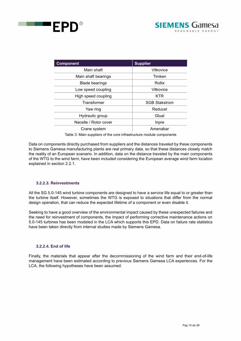
In addition to these processes, which are the ones related to the main components, in the following table
other suppliers that have been considered for the LCA are also listed. The manufacturing processes
carried out by these suppliers, have been analyzed using manufacturing processes from Ecoinvent 3.5
(cut-off) database.
Pag 15 de 29
Component Supplier
Main shaft Vitkovice
Main shaft bearings Timken
Blade bearings Rollix
Low speed coupling Vitkovice
High speed coupling KTR
Transformer SGB Stakstrom
Yaw ring Reducel
Hydraulic group Glual
Nacelle / Rotor cover Inpre
Crane system Amenabar
Table 3: Main suppliers of the core infrastructure module components
Data on components directly purchased from suppliers and the distances traveled by these components
to Siemens Gamesa manufacturing plants are real primary data, so that these distances closely match
the reality of an European scenario. In addition, data on the distance traveled by the main components
of the WTG to the wind farm, have been included considering the European average wind farm location
explained in section 2.2.1.
3.2.2.3. Reinvestments
All the SG 5.0-145 wind turbine components are designed to have a service life equal to or greater than
the turbine itself. However, sometimes the WTG is exposed to situations that differ from the normal
design operation, that can reduce the expected lifetime of a component or even disable it.
Seeking to have a good overview of the environmental impact caused by these unexpected failures and
the need for reinvestment of components, the impact of performing corrective maintenance actions on
5.0-145 turbines has been modeled in the LCA which supports this EPD. Data on failure rate statistics
have been taken directly from internal studies made by Siemens Gamesa.
3.2.2.4. End of life
Finally, the materials that appear after the decommissioning of the wind farm and their end-of-life
management have been estimated according to previous Siemens Gamesa LCA experiences. For the
LCA, the following hypotheses have been assumed.

Pag 16 de 29
Sub-system End of life hypothesis
Foundation materials Above ground surface is removed and the rest is
left in situ
Tower Fully recyclable.
Blades 95 % Landfilled
5 % Repaired
Blade bearings Fully recyclable
Hub Fully recyclable
Rotor cover Landfilled
Nacelle cover Landfilled
Beam system / Nacelle structure Fully recyclable
Main shaft Fully recyclable
High speed shaft Fully reusable / repairable
Gearbox Fully reusable / repairable
Generator 90 % Recycled
10 % Landfilled
Transformer 85 % Recycled
15 % Landfilled
Pitch system Fully reusable / repairable
Hydraulic group Fully reusable / repairable
Yaw system Fully recyclable
Crane system Fully repairable
Electrical cabinets / converter 90 % Recycled
10 % Landfilled
Wind farm wiring and WTG cables 95 % Recycled
5 % Landfilled
Table 4: End of life hypotheses
3.2.3. Core – Process
All the environmental impacts associated with the operation of the wind farm, given its 20 years of life,
have been considered in this module. One of the main advantages of the wind energy over other non-
renewable sources of energy is its independence on fossil fuels. This environmental benefit is reflected
at this stage when we look at the results.
In the core-process module the following concepts have been considered:
• Preventive maintenance required during the lifespan of the wind farm, including the
maintenance staff trips to the wind farm;
• The proper waste management of the consumables needed during operation and maintenance
of the wind farm, including transportation stage to the authorized entity for later treatment.

Pag 17 de 29
Figure 4: Blade manufacturing in Siemens Gamesa
Finally, the core also contains a vital part of the wind turbine life cycle, which is the technical
performance. Factors such as the annual energy production, the availability of the machine, the electrical
losses during operation or the energy self-consumption of the turbine for its auxiliary systems, have a
decisive influence on the environmental impact of the functional unit. These are also primary data
directly provided by the manufacturer.
3.2.4. Downstream
Lastly, the downstream stage comprises all the impacts that happen from the moment when the energy
is delivered to the electricity network (leaving this way the wind farm), until the moment when it reaches
the final consumer.
The downstream module represents mainly two different environmental impacts. The first one is the
impact related to the construction and decommissioning of the electrical grid, which is considered within
the sub-module “downstream infrastructure”. The second impact is related to the electrical losses
inherent to the voltage transformations and to the Joule effect when transporting the generated
electricity, which are considered in the sub-module “downstream process”. Note that these losses
depend on the connection voltage of the final consumer.
Given the fact that the present study does not cover a specific site but an average European location,
the electrical losses that occur between the wind farm electrical substation and the main electricity
network, can’t be directly measured. Siemens Gamesa has experienced difficulties trying to separate
the distributed energy losses to every kind of European customer. Accordingly, an average value of 2,2%
until a 132 KV network has been used to simulate these electrical losses, according to European
Regulators Group for electricity and gas (ERGEG). This means that 2,2% of every generated Kwh, is
lost in the distribution network between the wind farm and the declared customer.
On the other hand, the distance between the wind farm transformer station and the connection point to
the electrical grid is a variable value dependent on the specific location. According to previous Siemens
Gamesa experiences, this value could be assumed to be 15 km average, which is the length of the line
modeled for the LCA. The data used for the modelization of this electrical network have been obtained
from the ecoinvent 3.5 (cut-off) database.

Pag 18 de 29
3.3. Eco-profile
In the following tables, the environmental performance of the SG 5.0-145 wind turbine from a life cycle
perspective is shown, in the separated phases that were described above. The characterization factors
for each of these impact categories have been extracted from the CML-IA environmental impact
assessment methodology (version 4.8 - August 2016), the Intergovernmental Panel on Climate Change
(IPCC 2013 – AR5), the AWARE method (WULCA recommendations on characterization model for water
scarcity 2015, 2017), and the LOTOS-EUROS methodology as applied in the ReCiPe LCIA method
2008.
The EPD verifier had access to more comprehensive information on the LCA, which supports this
declaration. The functional unit, to which all outcomes are referred to is:
3.3.1. Potential environmental impacts
Potential environmental impacts
Unit Upstream Core
process Core
Infrastructure Total
generated Downstream
process Downstream infrastructure
Total distributed
Global warming potential
Fossil
g CO2 eq
2.15E-02 7.40E-02 6.47E+00 6.56E+00 1.44E-01 2.47E-01 6.95E+00
Biogenic 1.69E-05 2.54E-05 6.60E-02 6.61E-02 1.45E-03 4.01E-04 6.79E-02
Land use and transform.
2.48E-04 1.81E-05 5.57E-03 5.84E-03 1.28E-04 7.07E-04 6.67E-03
TOTAL 2.18E-02 7.41E-02 6.54E+00 6.63E+00 1.46E-01 2.49E-01 7.03E+00
Photochemical oxidant formation potential
g NMVOC
eq 1.75E-04 1.73E-04 3.80E-02 3.83E-02 8.43E-04 1.03E-03 4.02E-02
g C2H4eq 6.65E-06 8.32E-06 2.60E-03 2.61E-03 5.75E-05 1.31E-04 2.80E-03
Acidification potential g SO2 eq 1.00E-04 1.69E-04 4.23E-02 4.26E-02 9.37E-04 1.74E-03 4.53E-02
Eutrophication potential
g PO43-
eq 2.27E-05 6.27E-05 3.47E-02 3.47E-02 7.64E-04 7.78E-04 3.63E-02
Particulate matter g PM2.5
eq 1.10E-05 2.55E-05 6.94E-03 6.98E-03 1.54E-04 2.87E-04 7.42E-03
Abiotic depletion potential - Elements
g Sb eq 6.76E-08 5.41E-07 6.00E-04 6.00E-04 1.32E-05 4.87E-06 6.18E-04
Abiotic depletion potential – Fossil fuels
MJ, net calorific value
8.67E-04 5.96E-04 7.86E-02 8.01E-02 1.76E-03 2.34E-03 8.42E-02
Water scarcity potential
m3 eq 3.77E-06 5.69E-06 2.36E-03 2.37E-03 5.22E-05 5.28E-05 2.48E-03
Table 5: Potential environmental impacts
Functional unit
1 kWh net of electricity generated through an onshore wind farm of Siemens Gamesa SG 5.0-145
wind turbine generators, located in a European scenario and operating under medium wind
conditions (IEC II), and thereafter distributed to a 132 kV European electrical grid.
Pag 19 de 29
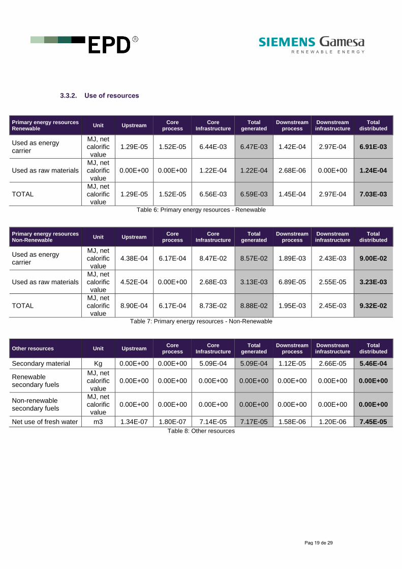
3.3.2. Use of resources
Primary energy resources Renewable
Unit Upstream Core
process Core
Infrastructure Total
generated Downstream
process Downstream infrastructure
Total distributed
Used as energy carrier
MJ, net calorific value
1.29E-05 1.52E-05 6.44E-03 6.47E-03 1.42E-04 2.97E-04 6.91E-03
Used as raw materials MJ, net calorific value
0.00E+00 0.00E+00 1.22E-04 1.22E-04 2.68E-06 0.00E+00 1.24E-04
TOTAL MJ, net calorific value
1.29E-05 1.52E-05 6.56E-03 6.59E-03 1.45E-04 2.97E-04 7.03E-03
Table 6: Primary energy resources - Renewable
Primary energy resources Non-Renewable
Unit Upstream Core
process Core
Infrastructure Total
generated Downstream
process Downstream infrastructure
Total distributed
Used as energy carrier
MJ, net calorific value
4.38E-04 6.17E-04 8.47E-02 8.57E-02 1.89E-03 2.43E-03 9.00E-02
Used as raw materials MJ, net calorific value
4.52E-04 0.00E+00 2.68E-03 3.13E-03 6.89E-05 2.55E-05 3.23E-03
TOTAL MJ, net calorific value
8.90E-04 6.17E-04 8.73E-02 8.88E-02 1.95E-03 2.45E-03 9.32E-02
Table 7: Primary energy resources - Non-Renewable
Other resources Unit Upstream Core
process Core
Infrastructure Total
generated Downstream
process Downstream infrastructure
Total distributed
Secondary material Kg 0.00E+00 0.00E+00 5.09E-04 5.09E-04 1.12E-05 2.66E-05 5.46E-04
Renewable secondary fuels
MJ, net calorific value
0.00E+00 0.00E+00 0.00E+00 0.00E+00 0.00E+00 0.00E+00 0.00E+00
Non-renewable secondary fuels
MJ, net calorific value
0.00E+00 0.00E+00 0.00E+00 0.00E+00 0.00E+00 0.00E+00 0.00E+00
Net use of fresh water m3 1.34E-07 1.80E-07 7.14E-05 7.17E-05 1.58E-06 1.20E-06 7.45E-05
Table 8: Other resources

Pag 20 de 29
3.3.3. Waste production and output flows
Waste production Unit Upstream Core
process Core
Infrastructure Total
generated Downstream
process Downstream infrastructure
Total distributed
Hazardous waste disposed
Kg 3.29E-10 1.41E-09 2.47E-05 2.47E-05 5.43E-07 2.88E-08 2.53E-05
Non-hazardous waste disposed
Kg 1.82E-06 1.69E-05 6.13E-03 6.15E-03 1.35E-04 4.93E-05 6.33E-03
Ash Kg 2.67E-08 1.36E-07 1.85E-05 1.87E-05 4.12E-07 1.28E-06 2.04E-05
Inert waste Kg 1.79E-06 1.67E-05 6.11E-03 6.13E-03 1.35E-04 4.80E-05 6.31E-03
Radioactive waste disposed
Kg 6.22E-09 3.71E-09 3.07E-07 3.17E-07 6.97E-09 4.19E-09 3.28E-07
Table 9: Waste production
Output flows Unit Upstream Core
process Core
Infrastructure Total
generated Downstream
process Downstream infrastructure
Total distributed
Components for reuse Kg 0.00E+00 0.00E+00 0.00E+00 0.00E+00 0.00E+00 0.00E+00 0.00E+00
Material for recycling Kg 0.00E+00 0.00E+00 1.05E-03 1.05E-03 2.32E-05 5.07E-05 1.13E-03
Materials for energy recovery
Kg 0.00E+00 1.12E-05 0.00E+00 1.12E-05 2.47E-07 2.91E-07 1.18E-05
Table 10: Output flows
Pag 21 de 29
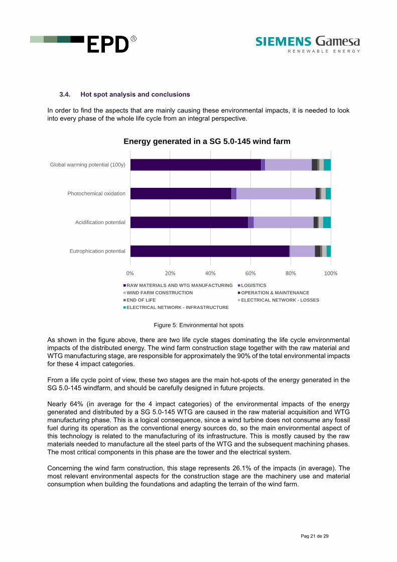
3.4. Hot spot analysis and conclusions
In order to find the aspects that are mainly causing these environmental impacts, it is needed to look
into every phase of the whole life cycle from an integral perspective.
Figure 5: Environmental hot spots
As shown in the figure above, there are two life cycle stages dominating the life cycle environmental
impacts of the distributed energy. The wind farm construction stage together with the raw material and
WTG manufacturing stage, are responsible for approximately the 90% of the total environmental impacts
for these 4 impact categories.
From a life cycle point of view, these two stages are the main hot-spots of the energy generated in the
SG 5.0-145 windfarm, and should be carefully designed in future projects.
Nearly 64% (in average for the 4 impact categories) of the environmental impacts of the energy
generated and distributed by a SG 5.0-145 WTG are caused in the raw material acquisition and WTG
manufacturing phase. This is a logical consequence, since a wind turbine does not consume any fossil
fuel during its operation as the conventional energy sources do, so the main environmental aspect of
this technology is related to the manufacturing of its infrastructure. This is mostly caused by the raw
materials needed to manufacture all the steel parts of the WTG and the subsequent machining phases.
The most critical components in this phase are the tower and the electrical system.
Concerning the wind farm construction, this stage represents 26.1% of the impacts (in average). The
most relevant environmental aspects for the construction stage are the machinery use and material
consumption when building the foundations and adapting the terrain of the wind farm.
0% 20% 40% 60% 80% 100%
Eutrophication potential
Acidification potential
Photochemical oxidation
Global warming potential (100y)
Energy generated in a SG 5.0-145 wind farm
RAW MATERIALS AND WTG MANUFACTURING LOGISTICS
WIND FARM CONSTRUCTION OPERATION & MAINTENANCE
END OF LIFE ELECTRICAL NETWORK - LOSSES
ELECTRICAL NETWORK - INFRASTRUCTURE

Pag 22 de 29
Finally, the rest of the modules such as use and maintenance, end of life, electrical losses in the network
and logistics, have a minor contribution to the life cycle environmental impacts of the generated and
distributed energy using SG 5.0-145 WTGs. More detailed conclusions on the environmental impacts
were made in the full LCA report. Please, refer to Siemens Gamesa Renewable Energy for further
information.
4. Additional environmental impact
4.1. Biodiversity protection
Siemens Gamesa products and services, use certain natural resources (water, fossil fuels and wind) to
perform its activities, thereby interacting with, and potentially affecting, ecosystems, landscapes and
species. This mainly happens across our operations over the product life cycle, for example:
• When we establish new facilities;
• When constructing our wind power plants.
Some impacts to biodiversity can include, for example:
• Potential land use changes by using vehicles and machinery to open up paths and remove
vegetation;
• Prolonged human presence which temporarily affects the behavior of species of fauna in a
generally reversible way;
• Potential species mortality due to collisions with our customers’ wind turbines.
Despite these potential impacts on biodiversity, Siemens Gamesa wind projects are constructed in a
sustainable way allowing a balanced coexistence, thus conserving and protecting natural assets, i.e.
biodiversity and climate. This respect for biodiversity and ecosystems plays a leading role in the
company’s business strategy. There are different regulatory and voluntary instruments to achieve a
positive net balance in relation to biodiversity and the environment, including:
• Company policies and procedures under the integrated management system;
• Full compliance with permits granted by environmental and conservation authorities at each
region, which set out requirements to ensure the local environment’s protection;
• Setting environmental and control plans and implementing management systems, the majority
of which have been certified according to the ISO 14001 standard to prevent and control
environmental risks;
• Fulfilling legislation on conducting environmental impact studies, which include analysis and
prevention mechanisms that consider different alternatives and lay down corrective measures
to avoid, mitigate or offset any possible damage.
As a general rule, protected areas and areas of high biodiversity value without protection are avoided
during the design stage of new infrastructures. Potential environmental impacts are analyzed through a
formal HSE aspects evaluation and by conducting environmental impact assessments beforehand, with
measures to correct and minimize the impacts. In case that they cannot be completely mitigated,
offsetting measures are taken.

Pag 23 de 29
The company has activities in some areas where threatened species included in the IUCN Red List and
in other national conservation lists live or could be present. This, however, does not mean that they are
affected or threatened by such activities. Hence, the identification of species on the IUCN Red List and
other species included in national conservation lists which could be affected by Siemens Gamesa’s
activities is permanently monitored to take the necessary measures to avoid endangering them.
4.2. Land use
As this EPD is not relative to one specific site in Europe, but to an average European Siemens Gamesa
location, a specific land use analysis cannot be performed. Alternatively, a description on the land uses
across Europe, has been performed.
The data source used for the land use and land cover classes information in Europe, are the maps
published by the Copernicus Land Monitoring system. Copernicus, is a European system for monitoring
the Earth. Data is collected by different sources, including Earth observation satellites and in-situ
sensors. The data is processed and provides reliable and up-to-date information in six thematic areas:
land, marine, atmosphere, climate change, emergency management and security.
4.2.1. Description of land cover classes across Europe
The following table shows the land cover classes across the area for which the study is representative.
The surface is expressed in hectares. The bigger areas in Europe are occupied by non-irrigated arable
lands as well as by coniferous and mixed forest, which will be the most common affected areas when a
new wind farm is built.
Land cover classes Surface (ha) %
Urban fabric 21,587,189 4.1%
Other artificial areas 1,606,124 0.3%
Non-irrigated arable land 109,894,155 21.0%
Permanently irrigated arable land 4,695,274 0.9%
Pastures 41,045,873 7.9%
Other agricultural areas 55,442,269 10.6%
Broad-leaved forest 55,083,970 10.5%
Coniferous and mixed forest 104,911,554 20.1%
Other shrub and/or herbaceous areas 76,061,803 14.6%
Beaches, sands and rocks 23,490,231 4.5%
Burnt areas 223,000 0.0%
Wetlands 14,410,030 2.8%
Water bodies 13,962,613 2.7%
TOTAL 522,414,084 100.0%
Table 11: Land cover classes across Europe
Pag 24 de 29
4.2.2. Description of the activities on the occupied areas
The area of land occupied by artificial elements in a 8 wind turbine windfarm will be approximately of
174,240 m2. This area will be mainly occupied by the following artificial elements during 20 years and 6
months, including the construction, operation and dismantling periods of the windfarm:
• Foundations;
• Turbines;
• Tracks / roads;
• Control buildings;
• Electrical substation compounds;
• Trenches for internal wiring.
NMENL RISKS
4.3. Environmental risks
Although the probability and severity of undesirable events is very low, the most representative
environmental risk is the accidental oil spill. The environmental management system currently in place
at Siemens Gamesa, prevents accidental spills through technical control elements (spill trays, loading
and unloading areas, storage of chemical products, protection of the rainwater network, etc.), along with
management mechanisms.
Should spills happen, Siemens Gamesa is equipped with environmental anomaly detection, reporting
and correction methods which are aimed at preventing this kind of events from being repeated.
Significant spills are construed as spills that cause damage to the facility’s external surroundings. Small
spills are defined as spills with an actual consequence of moderate or lower corresponding to level 3 on
a 1-5 scale.
A total of 308 small spills were recorded during 2018. There was just one significant spill in the reporting
period, amounting to 1,700 liters of oil released from a pad-mounted transformer. All spills were reported
and corrected in accordance with internal procedures. None of these spills required any exceptional
corrective measures. When using the declared windfarm as reference, these spills happen less
frenquent than once in three years.
4.4. Electromagnetic fields
The 2014/35/UE Directive regulates the electromagnetic compatibility of equipment. It aims to ensure
the functioning of the internal market by requiring equipment to comply with an adequate level of
electromagnetic compatibility. The directive makes a clear distinction between apparatus and fixed
installations with regard to documentation of compliance with the protection requirements. The term
“fixed installation”, in the view of the European Commission, is a comprehensive term for electrical
installations consisting of different types of apparatus and other devices that are combined permanently
at an unchangeable location.
A formal conformity assessment of such installations is often difficult to perform and, in some cases,
even impossible due to their size and complexity. In addition, fixed installations are often subject to
constant change through which the formal conformity assessment of their undefined and changeable
EMC conditions also appears to be problematic. Wind turbine is transported to its site of installation in
Pag 25 de 29
separate parts and assembled on-site, erected and put into operation. It is operated exclusively at that
location. According to these requirements, a wind turbine is a fixed installation according to the definition
of terms in the EMC Directive.
For these reasons, the EMC Directive foregoes a formal conformity assessment and CE marking of
fixed installations. However, it stipulates that such installations must be installed according to generally
accepted rules of technology, and that the specifications for the intended use of the installed components
have been observed. The measures for compliance with the essential requirements of the EMC Directive
also has been documented in the technical file. In addition, the basic standard for the design of wind
turbines, EN 61400-1, obligates to EMC assessment and to the respective measurements. According
to the design risk assessment, there are not person exposed to electromagnetic radiation hazards in
the wind turbine.
4.5. Noise
The noise produced by a wind turbine is twofold, one mechanics and other aerodynamics. The first
comes from the machine components, and can easily be reduced by conventional techniques.
Aerodynamic noise produced by the air flowing on the blades tends to increase with the speed rotation
of the blades and with wind flow turbulent conditions noise may increase. Although inside the nacelle
mechanical noise exists, it is low compared to aerodynamic noise, and at ground level, the only relevant
noise is the aerodynamic one.
The emitted noise values are within the normal values within the wind industry. It is noteworthy that wind
farms are located in uninhabited areas and distances greater than 300 m the noise level is greatly
reduced and is considered negligible to be lower than the ambient noise threshold in nature, wind, etc.
Nevertheless, for locations with strict noise requirements, low noise operation modes are available. In
those versions, the total noise is limited to the required maximum value by reducing the power generated
in the most critical wind speed bins.
4.5.1. Noise calculation
There are two international standards establishing noise measurement procedure and noise levels
declaration:
• IEC 61400-11 (Ed. 3 2012): Wind turbine generator systems - Acoustic noise measurement
techniques. Definition of how to perform noise measurements of a wind turbine;
• IEC 61400-14 (Ed. 2005): Wind turbines - Declaration of apparent sound power level. Definition
of how to declare the noise generated by an AEG.
According to the measures carried out for the SG 5.0-145 wind turbine generator according to IEC
61400-14: 2005 and IEC 61400-11; 3rd Ed.; noise level is lower than 111.6 dBA.
Pag 26 de 29
4.6. Visual impact
The landscape impact caused by the presence of wind turbines and power lines is a subjective aspect,
which affects differently, depending on the location of the wind farm. The location of wind farms is also
determined by analyzing the different points from which they are visible to, thereby causing minimal
visual impact. Each wind farm prior to the decision to its location has had an environmental impact
assessment that has been approved by the relevant environmental authority.
In many cases, as part of the assessment process, interactive maps are used to illustrate the potential
effects of the wind turbines. These maps allow viewing the theoretical visibility of the proposed turbines,
zooming into an area and viewing photomontages from some particular viewpoints in the surrounding
area to see what the wind farm would look like.
5. Certification body and mandatory statements
5.1. Information from the certification body
The verification process of this environmental product declaration has been carried on by Tecnalia R&I
Certificación, accredited certification body by ENAC (the Spanish National Accreditation Body) and the
International EPD® System, which verifies that the attached Environmental Product Declaration
complies with the applicable reference documents and also certifies that the data presented by the
manufacturer are complete and traceable in order to provide supporting evidence of the environmental
impacts declared in this EPD document, according to the International EPD® System General
Programme Instructions.
The EPD has been made in accordance with the General Programme Instructions for the International
EPD® System, published by EPD International AB, and PCR 2007:08 - Electricity, steam, and hot water
generation & distribution - Version 4.0, valid until 2024-03-16.
This certification is valid until 2025-07-24.
5.2. Mandatory statements
5.2.1. General
Note that EPDs within the same product category but from different programmes may not be
comparable.
5.2.2. Life cycle stages omitted
According to the reference PCR, the phase of electricity use has been omitted, since the use of electricity
fulfils various functions in different contexts.

Pag 27 de 29
5.2.3. Means of obtaining explanatory materials
The ISO 14025 standard requires that the explanatory material should be available if the EPD will be
communicated to end users. This EPD is industrial consumer oriented (B2B) and communication is not
intended for B2C (Business-to-consumer).
5.2.4. Responsibility of the verifier and the programme operator
The verifier and the programme operator do not make any claim nor have any responsibility of the
legality of the product.
5.2.5. Ownership, liability and responsibility
The EPD owner has the sole ownership, liability and responsibility of the EPD.
5.2.6. EPD validity
An EPD should provide current information, and may be updated if conditions change. The stated
validity is therefore subject to the continued registration and publication at www.environdec.com.
Pag 28 de 29
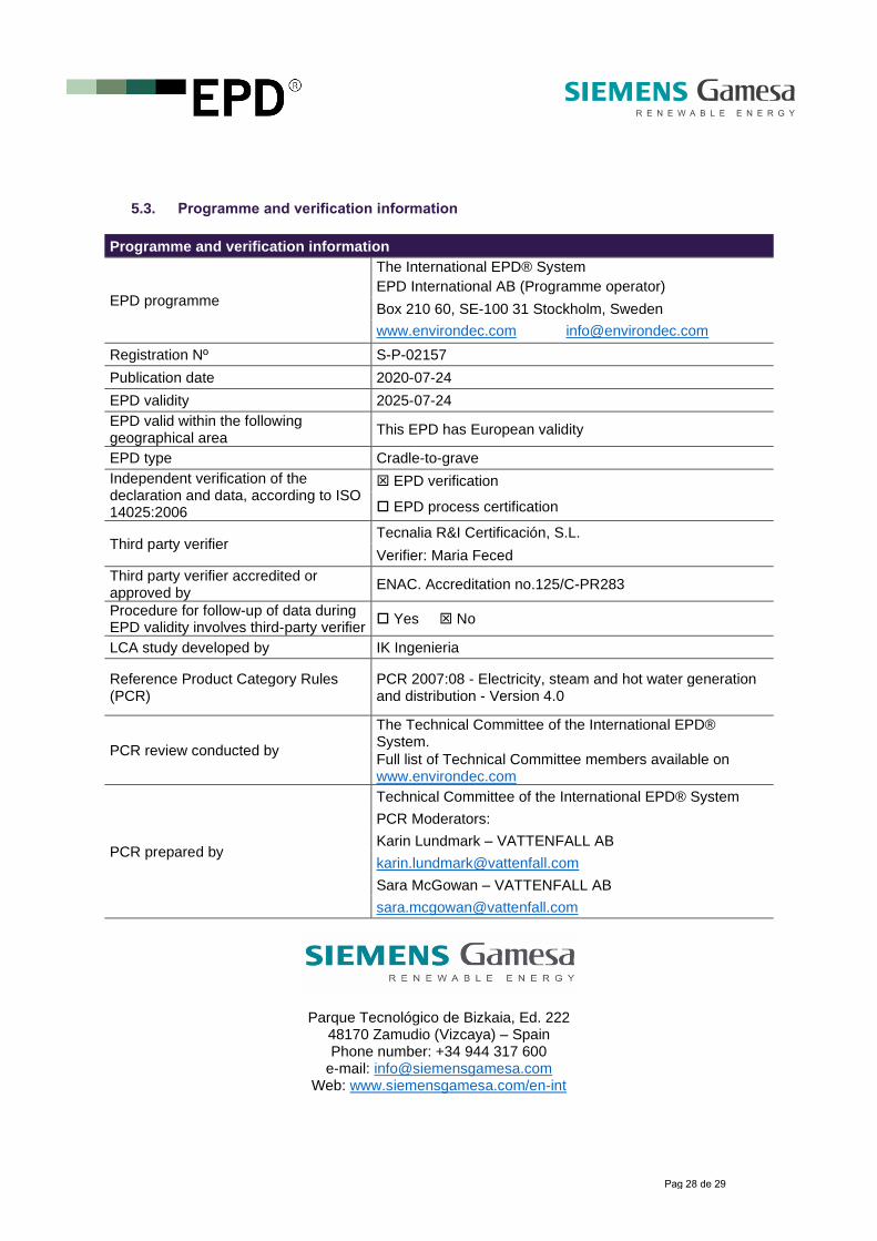
5.3. Programme and verification information
Programme and verification information
EPD programme
The International EPD® System
EPD International AB (Programme operator)
Box 210 60, SE-100 31 Stockholm, Sweden
www.environdec.com [email protected] Registration Nº S-P-02157
Publication date 2020-07-24
EPD validity 2025-07-24
EPD valid within the following geographical area
This EPD has European validity
EPD type Cradle-to-grave
Independent verification of the declaration and data, according to ISO 14025:2006
EPD verification
EPD process certification
Third party verifier Tecnalia R&I Certificación, S.L.
Verifier: Maria Feced
Third party verifier accredited or approved by
ENAC. Accreditation no.125/C-PR283
Procedure for follow-up of data during EPD validity involves third-party verifier
Yes No
LCA study developed by IK Ingenieria
Reference Product Category Rules (PCR)
PCR 2007:08 - Electricity, steam and hot water generation and distribution - Version 4.0
PCR review conducted by
The Technical Committee of the International EPD® System.
Full list of Technical Committee members available on www.environdec.com
PCR prepared by
Technical Committee of the International EPD® System
PCR Moderators:
Karin Lundmark – VATTENFALL AB
Sara McGowan – VATTENFALL AB
Parque Tecnológico de Bizkaia, Ed. 222 48170 Zamudio (Vizcaya) – Spain Phone number: +34 944 317 600
e-mail: [email protected] Web: www.siemensgamesa.com/en-int

Pag 29 de 29
6. Links and references
Additional information about Siemens Gamesa Renewable Energy:
www.siemensgamesa.com/en-int
Siemens Gamesa Renewable Energy sustainability commitment:
www.siemensgamesa.com/en-int/sustainability
Additional information about the International EPD® System:
www.environdec.com
The International EPD® System is based on a hierarchical approach using the following international
standards:
• ISO 9001, Quality management systems;
• ISO 14001, Environmental management systems;
• ISO 14040, LCA - Principles and procedures;
• ISO 14044, LCA - Requirements and guidelines;
• ISO 14025, Type III environmental declarations.
Data base used for the LCA:
EcoInvent 3.5 Database, published by the Swiss Centre for Life Cycle Inventories
http://www.ecoinvent.org