Electricity & Circuits: An introduction for neuroscientists.
28
Electricity & Circuits: An introduction for neuroscientists
-
Upload
braydon-searles -
Category
Documents
-
view
223 -
download
0
Transcript of Electricity & Circuits: An introduction for neuroscientists.
Electricity & Circuits:An introduction for neuroscientists
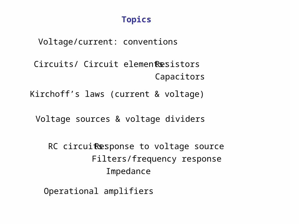
Voltage/current: conventions
ResistorsCircuits/ Circuit elements:
Kirchoff’s laws (current & voltage)
Capacitors
Voltage sources & voltage dividers
RC circuits: Response to voltage source
Filters/frequency response
Impedance
Operational amplifiers
Topics
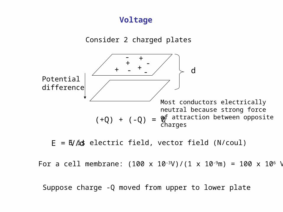
Voltage
Consider 2 charged plates
+
-+
+--
+
- dPotentialdifference
(+Q) + (-Q) = 0
Most conductors electricallyneutral because strong forceof attraction between oppositecharges
E = V/d E is electric field, vector field (N/coul)
Suppose charge -Q moved from upper to lower plate
For a cell membrane: (100 x 10-3V)/(1 x 10-9m) = 100 x 106 V/m
+
-
++
--
+
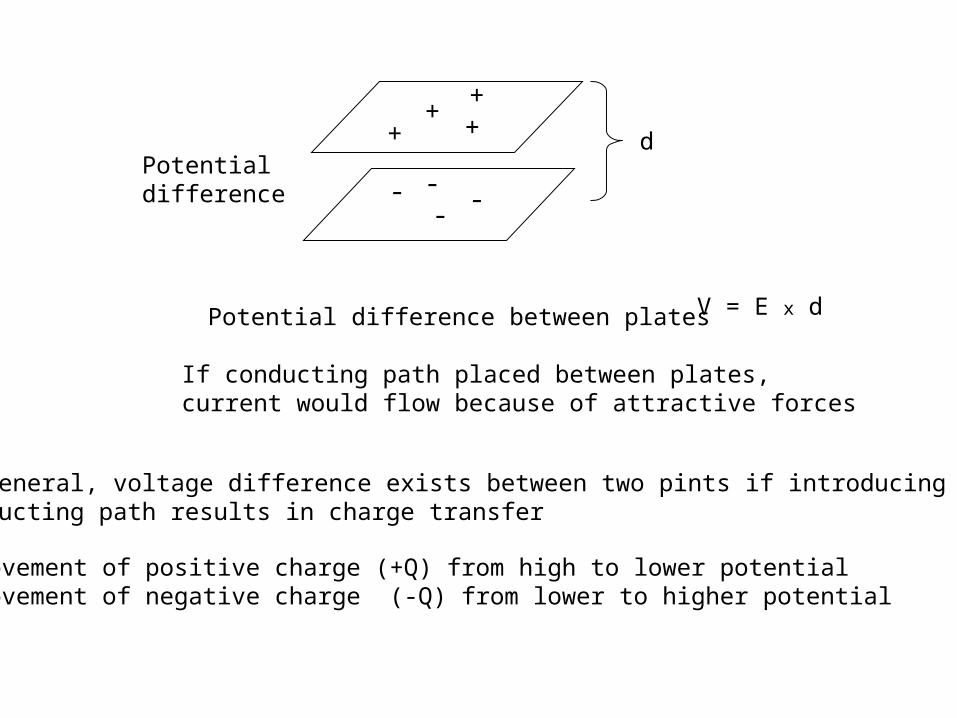
-Potentialdifference
d
Potential difference between plates
If conducting path placed between plates,current would flow because of attractive forces
In general, voltage difference exists between two pints if introducing aconducting path results in charge transfer
Movement of positive charge (+Q) from high to lower potentialMovement of negative charge (-Q) from lower to higher potential
V = E x d
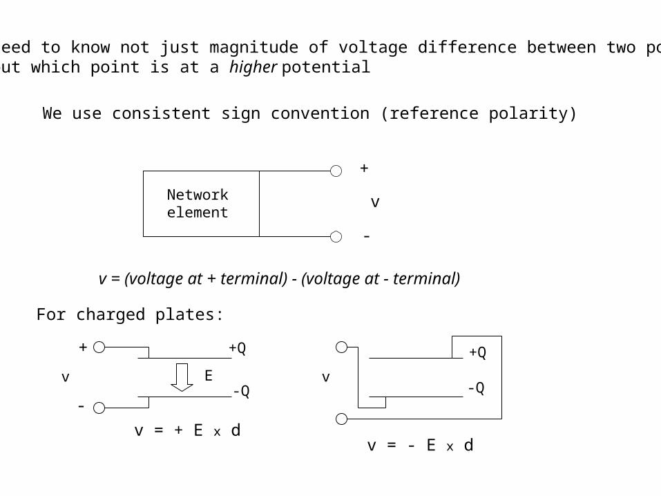
Need to know not just magnitude of voltage difference between two pointsbut which point is at a higher potential
We use consistent sign convention (reference polarity)
Networkelement
+
-
v
v = (voltage at + terminal) - (voltage at - terminal)
For charged plates:
+Q
-Q -Q
+Q
E
+
-
v = + E x d
v v
v = - E x d
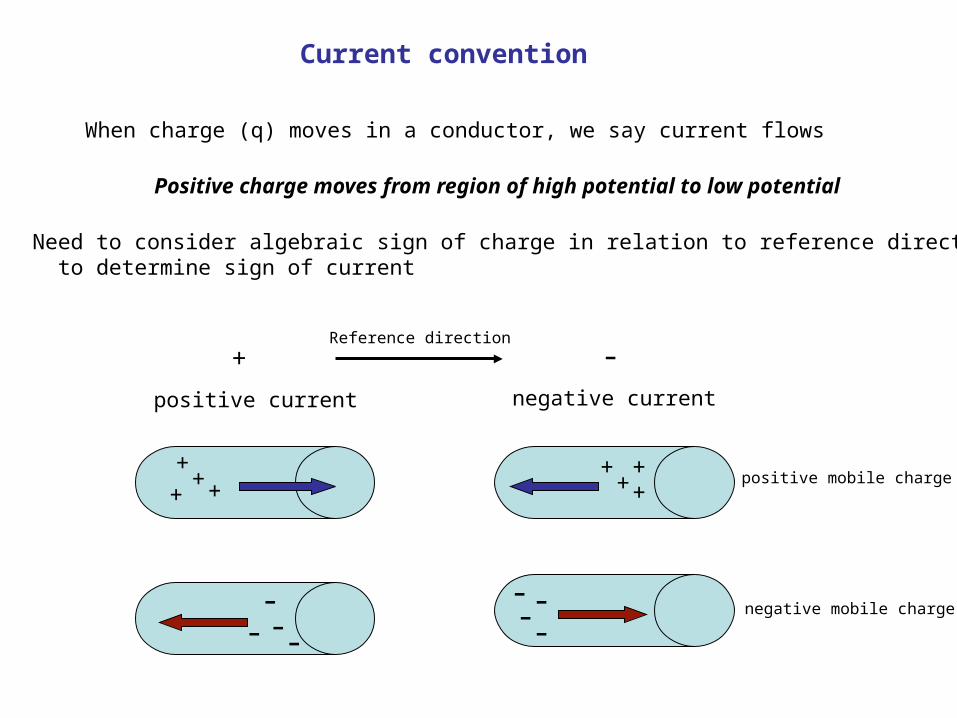
Current convention
When charge (q) moves in a conductor, we say current flows
Positive charge moves from region of high potential to low potential
Need to consider algebraic sign of charge in relation to reference direction to determine sign of current
+ -Reference direction
positive current negative current
++
+ ++++
+
- --
--- --
positive mobile charge
negative mobile charge
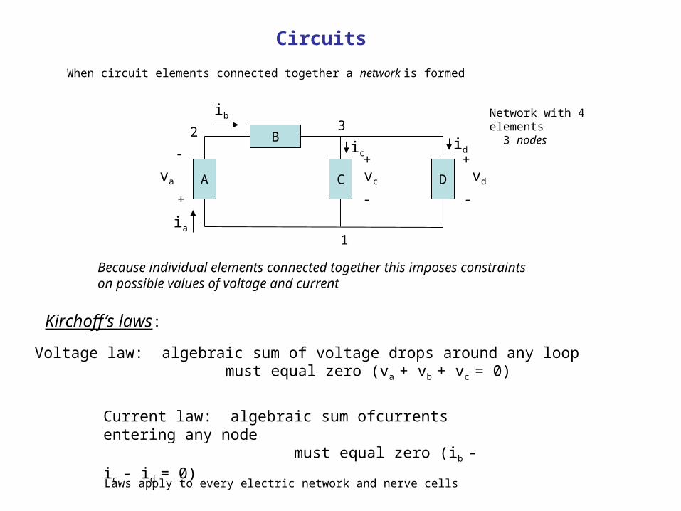
Circuits
B
C DA
When circuit elements connected together a network is formed
va
ia
+
-
ib
ic id
1
2 3Network with 4 elements 3 nodes
Because individual elements connected together this imposes constraintson possible values of voltage and current
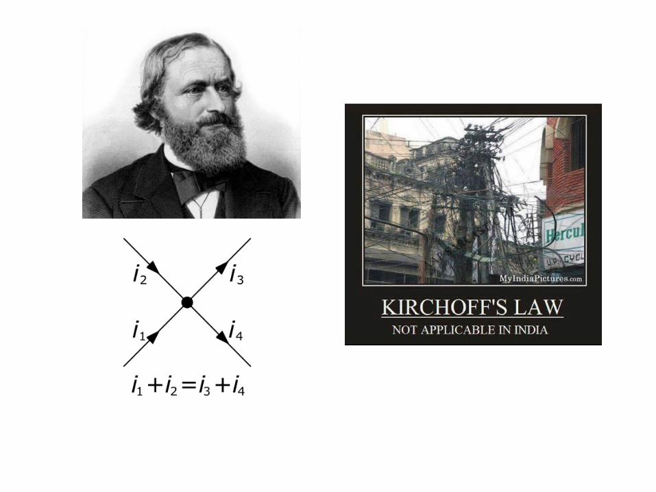
Kirchoff’s laws:
+
-
vc
+
-
vd
Voltage law: algebraic sum of voltage drops around any loop must equal zero (va + vb + vc = 0)
Current law: algebraic sum ofcurrents entering any node must equal zero (ib - ic - id = 0)
Laws apply to every electric network and nerve cells
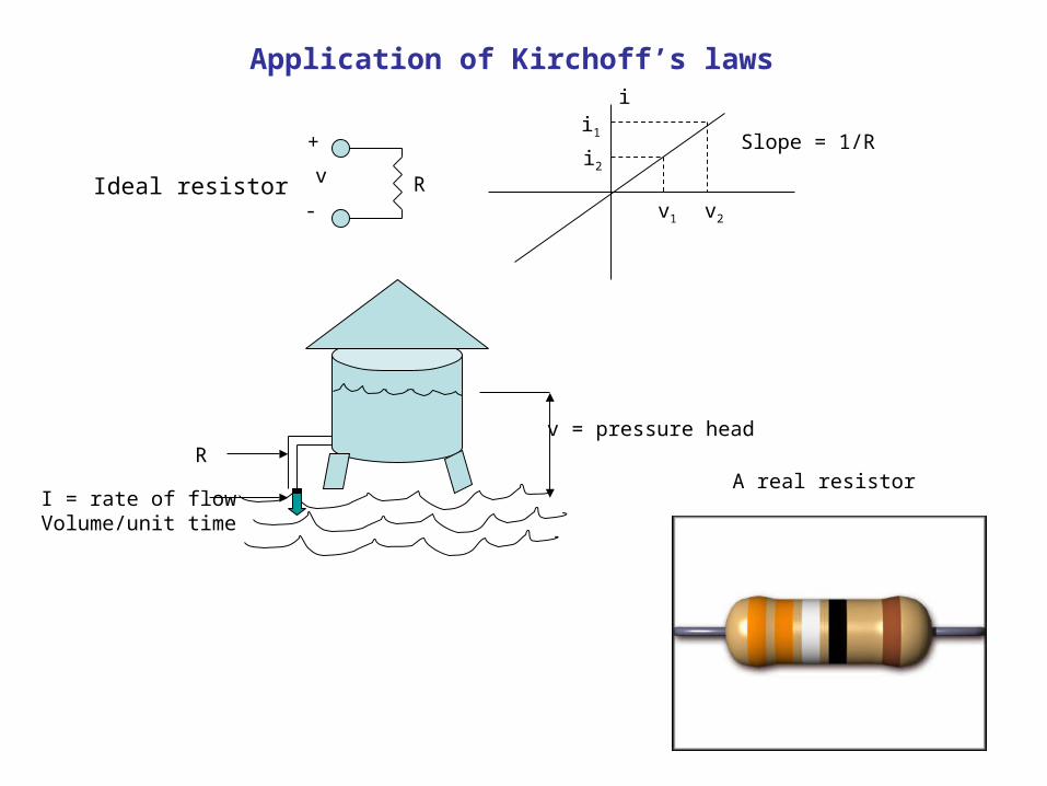
Application of Kirchoff’s laws
Ideal resistor Rv
+
-
ii1
i2
v1 v2
Slope = 1/R
v = pressure headR
I = rate of flowVolume/unit time
A real resistor
Ohm’s law
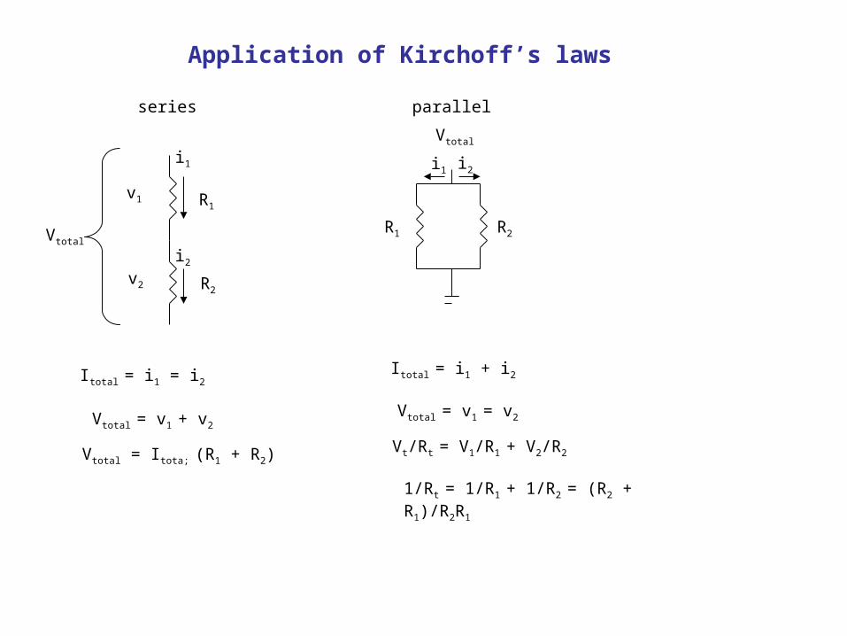
Application of Kirchoff’s laws
v1
v2
R1
R2
i1
i2
Vtotal
Itotal = i1 = i2
series parallel
Vtotal
R1 R2
i2i1
Vtotal = v1 + v2
Vtotal = Itota; (R1 + R2)
Itotal = i1 + i2
Vtotal = v1 = v2
Vt/Rt = V1/R1 + V2/R2
1/Rt = 1/R1 + 1/R2 = (R2 + R1)/R2R1
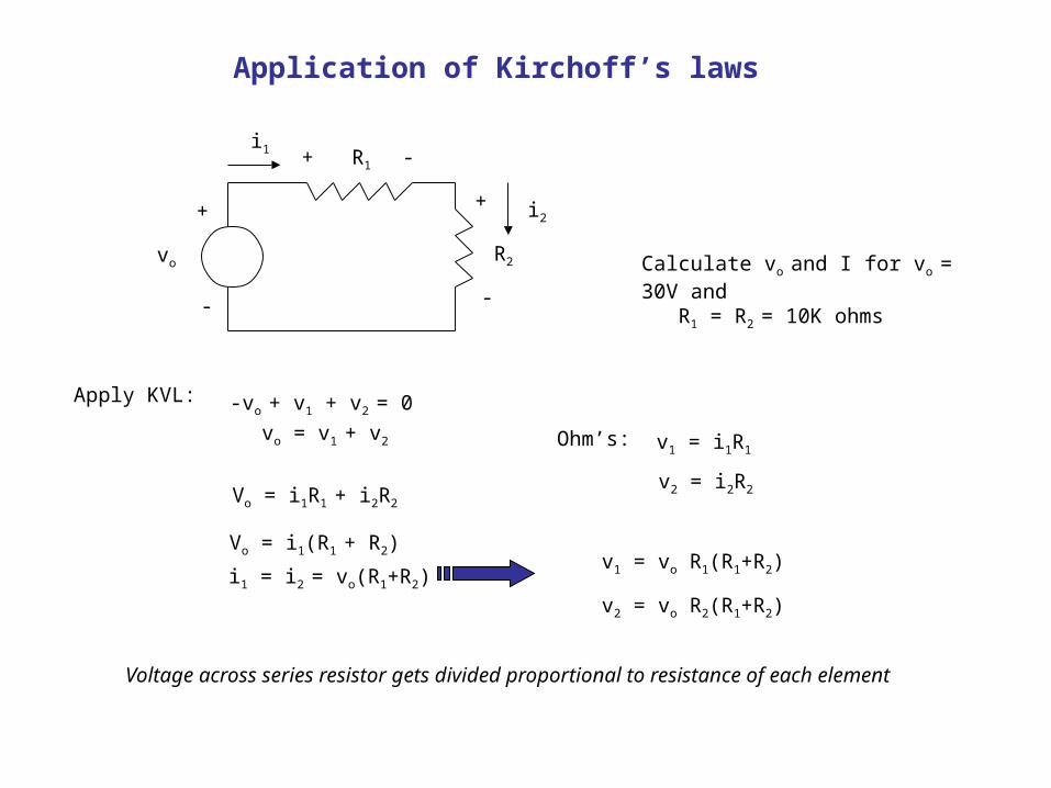
Application of Kirchoff’s laws
R1
R2vo
+
-
+ -
+
-
i1
i2
Apply KVL: -vo + v1 + v2 = 0
vo = v1 + v2 Ohm’s: v1 = i1R1
v2 = i2R2Vo = i1R1 + i2R2
Vo = i1(R1 + R2)
i1 = i2 = vo(R1+R2)v1 = vo R1(R1+R2)
v2 = vo R2(R1+R2)
Voltage across series resistor gets divided proportional to resistance of each element
Calculate vo and I for vo = 30V and R1 = R2 = 10K ohms
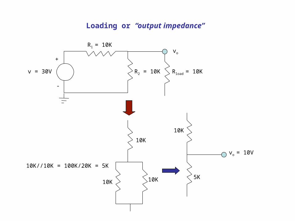
Loading or “output impedance”
R2 = 10Kv = 30V
+
-
vo
Rload = 10K
R1 = 10K
10K
10K
10K 10K 5K
vo = 10V
10K//10K = 100K/20K = 5K
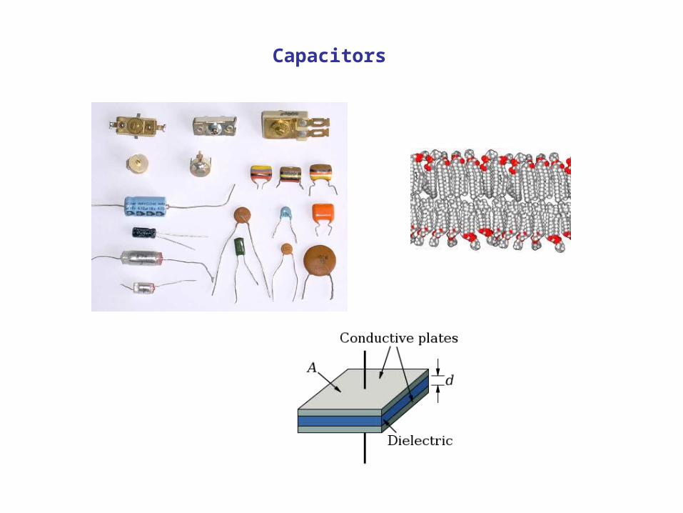
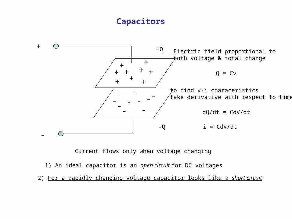
Capacitors
+
-
++
+ +
++
+++
--
--
--
-- -
+Q
-Q
Electric field proportional toboth voltage & total charge
Q = Cv
to find v-i characeristicstake derivative with respect to time
dQ/dt = CdV/dt
i = CdV/dt
Current flows only when voltage changing
1) An ideal capacitor is an open circuit for DC voltages
2) For a rapidly changing voltage capacitor looks like a short circuit
Capacitors
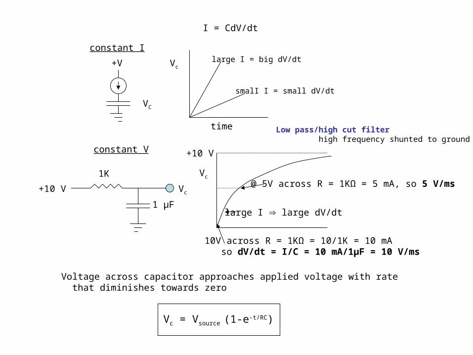
constant I
+V Vc
time
large I = big dV/dt
smalI I = small dV/dt
I = CdV/dt
constant V
1K
+10 V
1 µF
Vc
Vc
+10 V
large I large dV/dt
10V across R = 1KΩ = 10/1K = 10 mA so dV/dt = I/C = 10 mA/1µF = 10 V/ms
@ 5V across R = 1KΩ = 5 mA, so 5 V/ms
Voltage across capacitor approaches applied voltage with rate that diminishes towards zero
Vc = Vsource (1-e-t/RC)
Low pass/high cut filter high frequency shunted to ground
VC
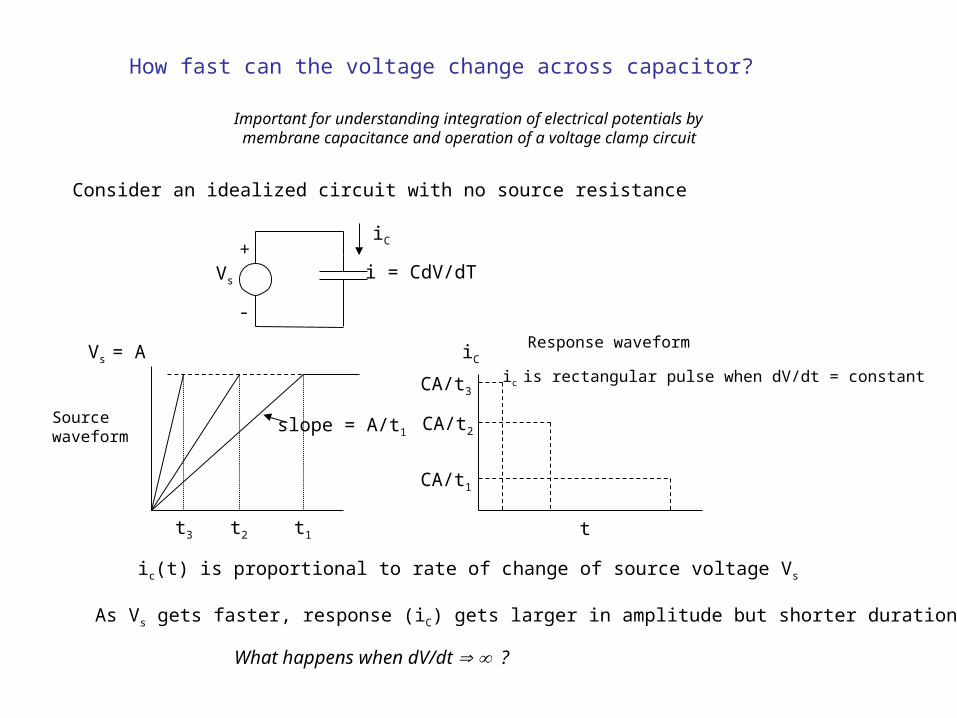
How fast can the voltage change across capacitor?
Important for understanding integration of electrical potentials by membrane capacitance and operation of a voltage clamp circuit
Consider an idealized circuit with no source resistance
Vs
+
-
i = CdV/dT
iC
Vs = A
slope = A/t1
t1t2t3
ic(t) is proportional to rate of change of source voltage Vs
t
Sourcewaveform
Response waveformiC
CA/t3
CA/t2
CA/t1
ic is rectangular pulse when dV/dt = constant
As Vs gets faster, response (iC) gets larger in amplitude but shorter duration
What happens when dV/dt ?
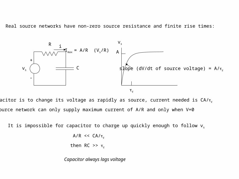
R
vs
i
C
+
-
Imax = A/R (Vs/R)
Real source networks have non-zero source resistance and finite rise times:
A
vs
tr
slope (dV/dt of source voltage) = A/tr
If capacitor is to change its voltage as rapidly as source, current needed is CA/tr
Source network can only supply maximum current of A/R and only when V=0
It is impossible for capacitor to charge up quickly enough to follow vs
A/R << CA/tr
Capacitor always lags voltage
then RC >> tr
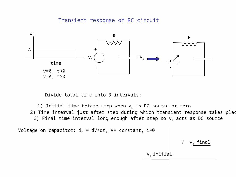
Transient response of RC circuit
vs
A
time
v=0, t<0v=A, t>0
vs vc
+
-
R
+-
R
Divide total time into 3 intervals:
1) Initial time before step when vs is DC source or zero
2) Time interval just after step during which transient response takes place3) Final time interval long enough after step so vs acts as DC source
Voltage on capacitor: ic = dV/dt, V= constant, i=0
vc initial
vc final?
R C
ic
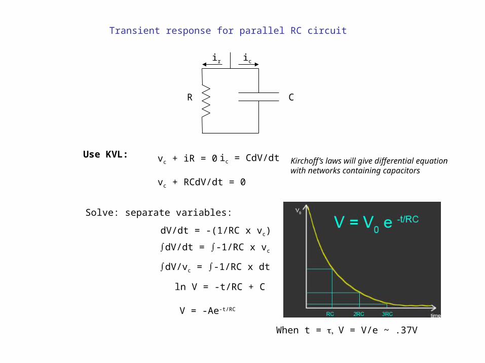
Transient response for parallel RC circuit
Use KVL: vc + iR = 0 ic = CdV/dt
vc + RCdV/dt = 0
Kirchoff’s laws will give differential equation with networks containing capacitors
Solve: separate variables:
dV/dt = -(1/RC x vc)
dV/dt = ∫-1/RC x vc
dV/vc = ∫-1/RC x dt
ln V = -t/RC + C
V = -Ae-t/RC
ir
When t = , t V = V/e ~ .37V
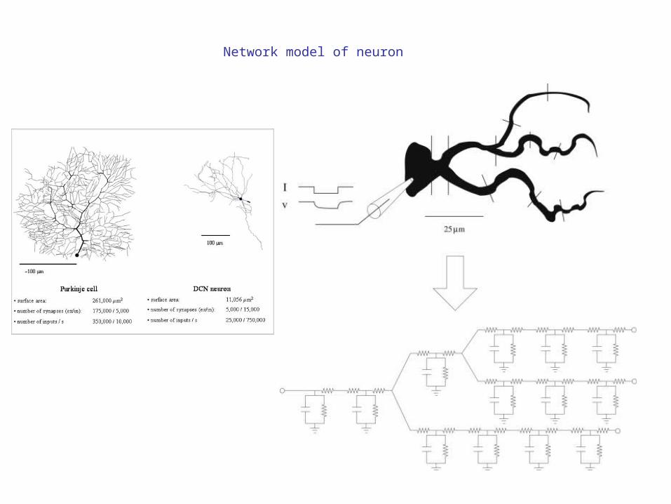
Network model of neuron
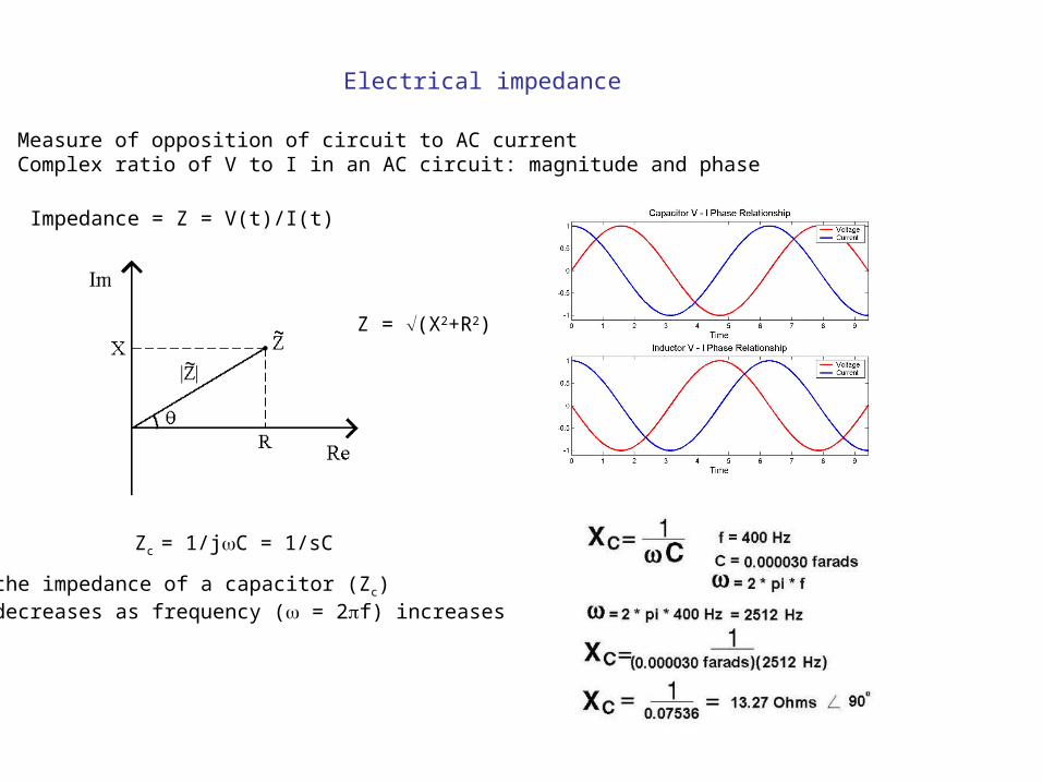
Electrical impedance
Measure of opposition of circuit to AC currentComplex ratio of V to I in an AC circuit: magnitude and phase
Impedance = Z = V(t)/I(t)
Z = (X2+R2)
Zc = 1/jC = 1/sC
the impedance of a capacitor (Zc)decreases as frequency (w = 2pf) increases
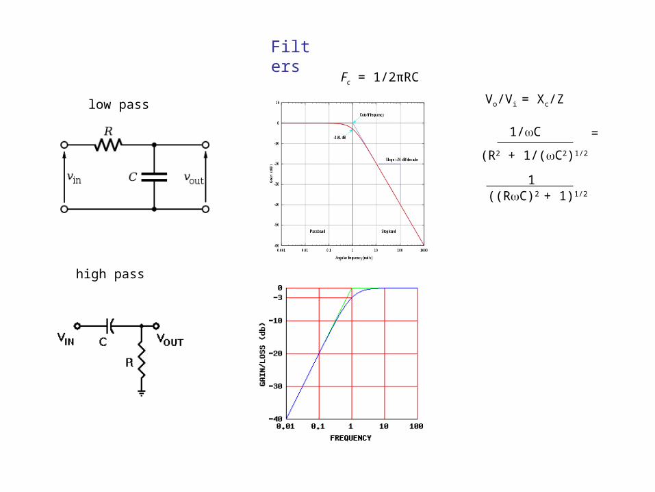
Filters
Fc = 1/2πRC
low pass
high pass
Vo/Vi = Xc/Z
1/wC
(R2 + 1/(wC2)1/2
=
1((RwC)2 + 1)1/2
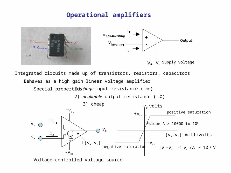
Operational amplifiers
Integrated circuits made up of transistors, resistors, capacitors
Behaves as a high gain linear voltage amplifier
Special properties: 1) huge input resistance ()
2) negligible output resistance (0)
3) cheap
v-
v+
-vcc
+vcc
i1
i2-+
+
-
vo
f(v+-v-)
Supply voltage
vo volts
+vcc
-vcc
positive saturation
negative saturation
(v+-v-) millivolts
slope A > 10000 to 106
|v+-v-| < vcc/A ~ 10-3 V
Voltage-controlled voltage source
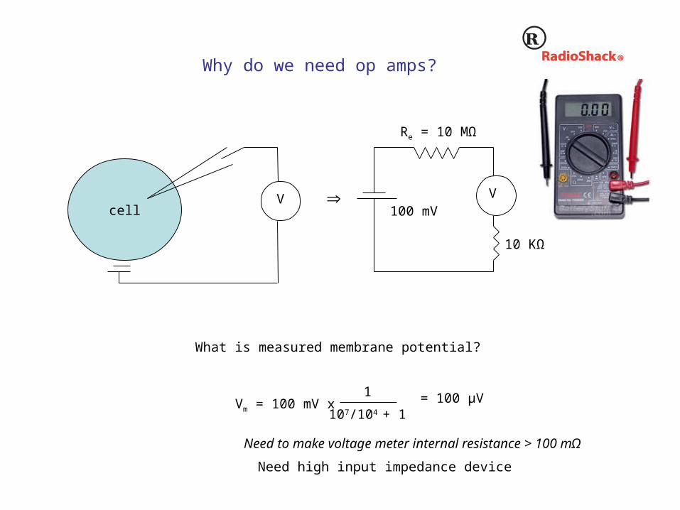
Why do we need op amps?
cellV V
Re = 10 MΩ
10 KΩ
What is measured membrane potential?
Vm = 100 mV x 1
107/104 + 1
100 mV
= 100 µV
Need to make voltage meter internal resistance > 100 mΩ
Need high input impedance device
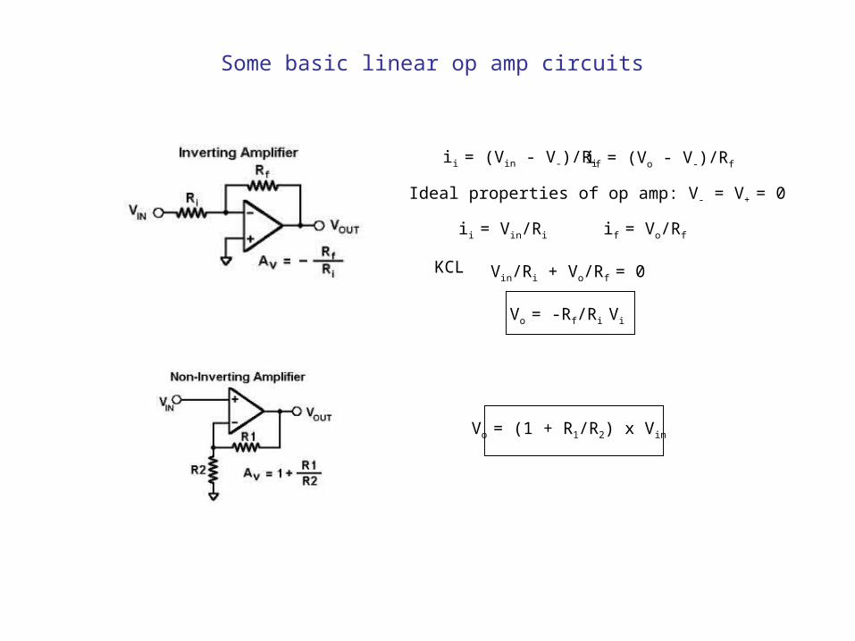
Some basic linear op amp circuits
ii = (Vin - V-)/Ri if = (Vo - V-)/Rf
Ideal properties of op amp: V- = V+ = 0
ii = Vin/Ri if = Vo/Rf
KCL Vin/Ri + Vo/Rf = 0
Vo = -Rf/Ri Vi
Vo = (1 + R1/R2) x Vin
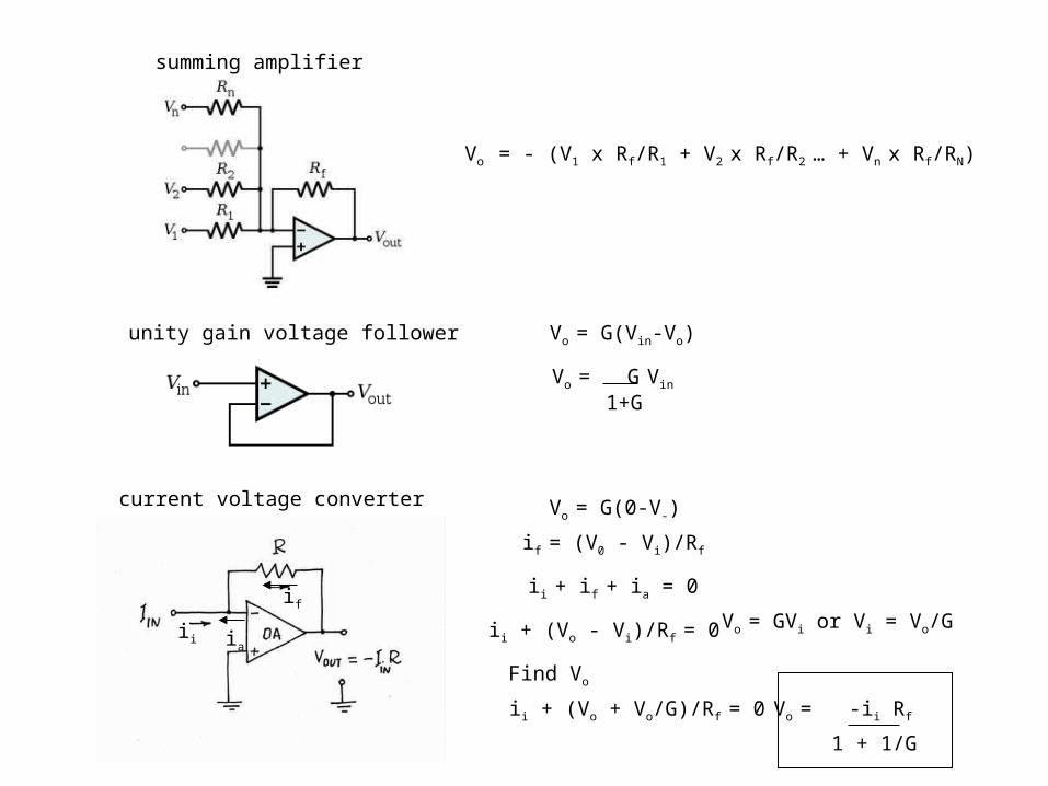
summing amplifier
unity gain voltage follower
current voltage converter
Vo = - (V1 x Rf/R1 + V2 x Rf/R2 … + Vn x Rf/RN)
Vo = G(0-V-)
if = (V0 - Vi)/Rf
if
ii ia
ii + if + ia = 0
ii + (Vo + Vo/G)/Rf = 0
Vo = GVi or Vi = Vo/G
Find Vo
ii + (Vo - Vi)/Rf = 0
Vo = -ii Rf
1 + 1/G
Vo = G(Vin-Vo)
Vo = G1+G
Vin
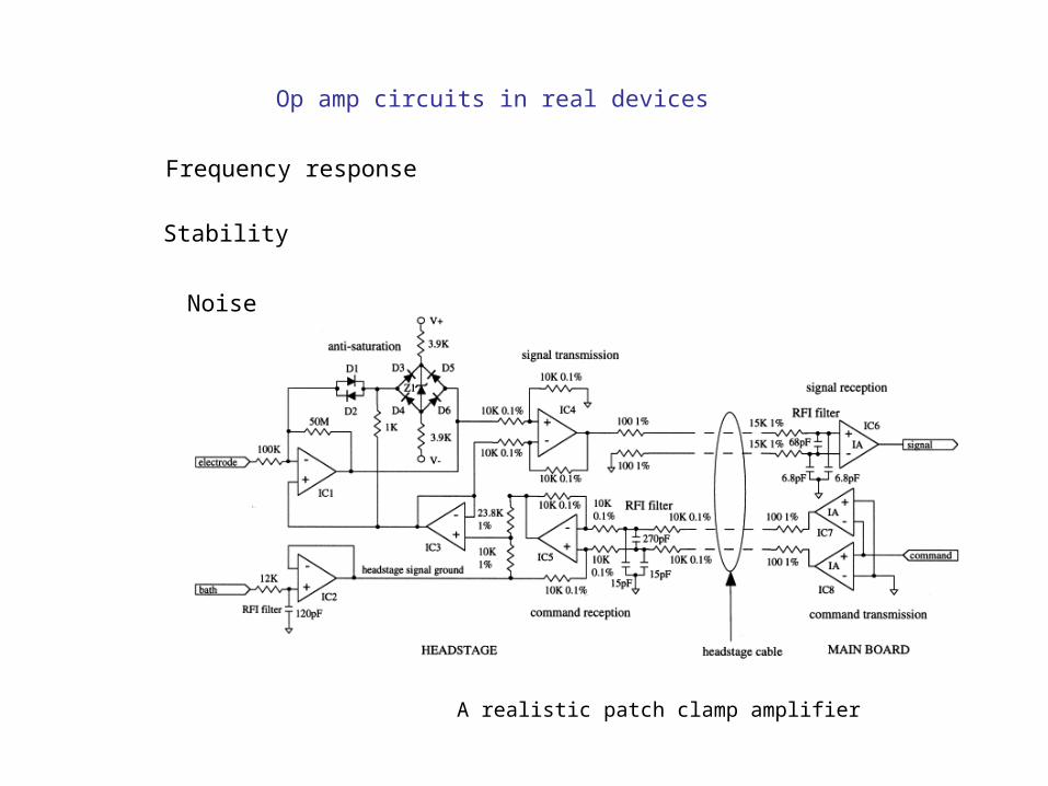
Op amp circuits in real devices
Frequency response
Stability
Noise
A realistic patch clamp amplifier