Electricity and Magnetism Transformers and...
18
Electricity and Magnetism Transformers and Alternating Current Lana Sheridan De Anza College Mar 19, 2018
-
Upload
trankhuong -
Category
Documents
-
view
216 -
download
3
Transcript of Electricity and Magnetism Transformers and...

Electricity and MagnetismTransformers and Alternating Current
Lana Sheridan
De Anza College
Mar 19, 2018

Last time
• RLC circuits and oscillations
• alternating current

Overview
• alternating current
• transformers
• rectifiers and filters

TransformersTransformers change ∆Vrms and Irms simultaneously, while keepingthe average power Pavg = Irms∆Vrms (resistive load) constant(conservation of energy).
850 CHAPTE R 31 E LECTROMAG N ETIC OSCI LLATION S AN D ALTE R NATI NG CU R R E NT
31-11 TransformersEnergy Transmission RequirementsWhen an ac circuit has only a resistive load, the power factor in Eq. 31-76 is cos 0° ! 1 and the applied rms emf !rms is equal to the rms voltage Vrms across theload. Thus, with an rms current Irms in the load, energy is supplied and dissipatedat the average rate of
Pavg ! !I ! IV. (31-77)
(In Eq. 31-77 and the rest of this section, we follow conventional practice and dropthe subscripts identifying rms quantities. Engineers and scientists assume that alltime-varying currents and voltages are reported as rms values; that is what the me-ters read.) Equation 31-77 tells us that, to satisfy a given power requirement, wehave a range of choices for I and V, provided only that the product IV is as required.
In electrical power distribution systems it is desirable for reasons of safety andfor efficient equipment design to deal with relatively low voltages at both the gener-ating end (the electrical power plant) and the receiving end (the home or factory).Nobody wants an electric toaster or a child’s electric train to operate at, say, 10 kV.On the other hand, in the transmission of electrical energy from the generating plantto the consumer, we want the lowest practical current (hence the largest practicalvoltage) to minimize I2R losses (often called ohmic losses) in the transmission line.
As an example, consider the 735 kV line used to transmit electrical energyfrom the La Grande 2 hydroelectric plant in Quebec to Montreal, 1000 km away.Suppose that the current is 500 A and the power factor is close to unity. Thenfrom Eq. 31-77, energy is supplied at the average rate
Pavg ! !I ! (7.35 " 105 V)(500 A) ! 368 MW.
The resistance of the transmission line is about 0.220 #/km; thus, there is a totalresistance of about 220 # for the 1000 km stretch. Energy is dissipated due to thatresistance at a rate of about
Pavg ! I 2R ! (500 A)2(220 #) ! 55.0 MW,
which is nearly 15% of the supply rate.Imagine what would happen if we doubled the current and halved the volt-
age. Energy would be supplied by the plant at the same average rate of 368 MWas previously, but now energy would be dissipated at the rate of about
Pavg ! I 2R ! (1000 A)2(220 #) ! 220 MW,
which is almost 60% of the supply rate. Hence the general energy transmissionrule:Transmit at the highest possible voltage and the lowest possible current.
The Ideal TransformerThe transmission rule leads to a fundamental mismatch between the requirementfor efficient high-voltage transmission and the need for safe low-voltage generationand consumption. We need a device with which we can raise (for transmission) andlower (for use) the ac voltage in a circuit, keeping the product current " voltage es-sentially constant.The transformer is such a device. It has no moving parts, operatesby Faraday’s law of induction, and has no simple direct-current counterpart.
The ideal transformer in Fig. 31-18 consists of two coils, with different num-bers of turns, wound around an iron core. (The coils are insulated from the core.)In use, the primary winding, of Np turns, is connected to an alternating-currentgenerator whose emf ! at any time t is given by
! ! !m sin vt. (31-78)
The secondary winding, of Ns turns, is connected to load resistance R, but its
Fig. 31-18 An ideal transformer (twocoils wound on an iron core) in a basictransformer circuit.An ac generator pro-duces current in the coil at the left (the pri-mary).The coil at the right (the secondary)is connected to the resistive load R whenswitch S is closed.
RVp Vs
S
Np
Ns
ΦB
Primary Secondary
halliday_c31_826-860hr.qxd 11-12-2009 13:11 Page 850
This works via mutual inductance. If the current in the first coildid not constantly change (AC) this would not work.
∆vs = ∆vpNs
Np
Transformers
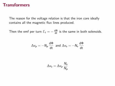
The reason for the voltage relation is that the iron core ideallycontains all the magnetic flux lines produced.
Then the emf per turn Et = − dΦdt is the same in both solenoids.
∆vp = −NpdΦ
dtand ∆vs = −Ns
dΦ
dt
∆vs = ∆vpNs
Np

Transformers
Let ∆V now refer to the rms voltage.
If ∆Vs > ∆Vp (and therefore Ns > Np), the transformer is called astep-up transformer.
This is a step up transformer:
850 CHAPTE R 31 E LECTROMAG N ETIC OSCI LLATION S AN D ALTE R NATI NG CU R R E NT
31-11 TransformersEnergy Transmission RequirementsWhen an ac circuit has only a resistive load, the power factor in Eq. 31-76 is cos 0° ! 1 and the applied rms emf !rms is equal to the rms voltage Vrms across theload. Thus, with an rms current Irms in the load, energy is supplied and dissipatedat the average rate of
Pavg ! !I ! IV. (31-77)
(In Eq. 31-77 and the rest of this section, we follow conventional practice and dropthe subscripts identifying rms quantities. Engineers and scientists assume that alltime-varying currents and voltages are reported as rms values; that is what the me-ters read.) Equation 31-77 tells us that, to satisfy a given power requirement, wehave a range of choices for I and V, provided only that the product IV is as required.
In electrical power distribution systems it is desirable for reasons of safety andfor efficient equipment design to deal with relatively low voltages at both the gener-ating end (the electrical power plant) and the receiving end (the home or factory).Nobody wants an electric toaster or a child’s electric train to operate at, say, 10 kV.On the other hand, in the transmission of electrical energy from the generating plantto the consumer, we want the lowest practical current (hence the largest practicalvoltage) to minimize I2R losses (often called ohmic losses) in the transmission line.
As an example, consider the 735 kV line used to transmit electrical energyfrom the La Grande 2 hydroelectric plant in Quebec to Montreal, 1000 km away.Suppose that the current is 500 A and the power factor is close to unity. Thenfrom Eq. 31-77, energy is supplied at the average rate
Pavg ! !I ! (7.35 " 105 V)(500 A) ! 368 MW.
The resistance of the transmission line is about 0.220 #/km; thus, there is a totalresistance of about 220 # for the 1000 km stretch. Energy is dissipated due to thatresistance at a rate of about
Pavg ! I 2R ! (500 A)2(220 #) ! 55.0 MW,
which is nearly 15% of the supply rate.Imagine what would happen if we doubled the current and halved the volt-
age. Energy would be supplied by the plant at the same average rate of 368 MWas previously, but now energy would be dissipated at the rate of about
Pavg ! I 2R ! (1000 A)2(220 #) ! 220 MW,
which is almost 60% of the supply rate. Hence the general energy transmissionrule:Transmit at the highest possible voltage and the lowest possible current.
The Ideal TransformerThe transmission rule leads to a fundamental mismatch between the requirementfor efficient high-voltage transmission and the need for safe low-voltage generationand consumption. We need a device with which we can raise (for transmission) andlower (for use) the ac voltage in a circuit, keeping the product current " voltage es-sentially constant.The transformer is such a device. It has no moving parts, operatesby Faraday’s law of induction, and has no simple direct-current counterpart.
The ideal transformer in Fig. 31-18 consists of two coils, with different num-bers of turns, wound around an iron core. (The coils are insulated from the core.)In use, the primary winding, of Np turns, is connected to an alternating-currentgenerator whose emf ! at any time t is given by
! ! !m sin vt. (31-78)
The secondary winding, of Ns turns, is connected to load resistance R, but its
Fig. 31-18 An ideal transformer (twocoils wound on an iron core) in a basictransformer circuit.An ac generator pro-duces current in the coil at the left (the pri-mary).The coil at the right (the secondary)is connected to the resistive load R whenswitch S is closed.
RVp Vs
S
Np
Ns
ΦB
Primary Secondary
halliday_c31_826-860hr.qxd 11-12-2009 13:11 Page 850
If ∆Vs < ∆Vp (and therefore Ns < Np), the transformer is called astep-down transformer.
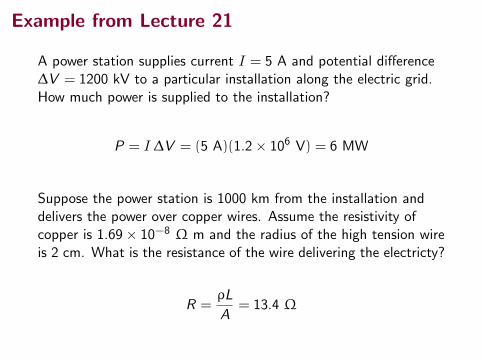
Example from Lecture 21
A power station supplies current I = 5 A and potential difference∆V = 1200 kV to a particular installation along the electric grid.How much power is supplied to the installation?
P = I ∆V = (5 A)(1.2× 10⁶ V) = 6 MW
Suppose the power station is 1000 km from the installation anddelivers the power over copper wires. Assume the resistivity ofcopper is 1.69× 10⁻⁸ Ω m and the radius of the high tension wireis 2 cm. What is the resistance of the wire delivering the electricty?
R =ρL
A= 13.4 Ω

Example from Lecture 21
How much power is dissipated as heat in the transmission lines tothe installation (current I = 5 A and potential difference∆V = 1200 kV are supplied to the station)?
P = I2R = (5 A)2(13.4 Ω) = 336 W
How much power would be dissipated as heat in the transmissionlines to the installation if instead the station supplied 6 MW ofpower with current I = 500 A and potential difference∆V = 12 kV?
P = I2R = (500 A)2(13.4 Ω) = 3.36 MW
Much more loss!

Transformers
Transmitting power at very high voltage and low current is muchmore efficient, though very high voltages are not safe or practicalfor household use.
Transformers allow for the voltage to be adjusted as needed.
This is the main reason why alternating current “won out” overdirect current for use as the mains power delivered to consumers.

TransformersThe circuit diagram for a transformer looks like:
1016 Chapter 33 Alternating-Current Circuits
99%. In the discussion that follows, let’s assume we are working with an ideal trans-former, one in which the energy losses in the windings and core are zero. Faraday’s law states that the voltage Dv1 across the primary is
Dv1 5 2N1 dFB
dt (33.39)
where FB is the magnetic flux through each turn. If we assume all magnetic field lines remain within the iron core, the flux through each turn of the primary equals the flux through each turn of the secondary. Hence, the voltage across the second-ary is
Dv2 5 2N2 dFB
dt (33.40)
Solving Equation 33.39 for dFB /dt and substituting the result into Equation 33.40 gives
Dv2 5N2
N1 Dv1 (33.41)
When N2 . N1, the output voltage Dv2 exceeds the input voltage Dv1. This configu-ration is referred to as a step-up transformer. When N2 , N1, the output voltage is less than the input voltage, and we have a step-down transformer. A circuit diagram for a transformer connected to a load resistance is shown in Figure 33.19. When a current I1 exists in the primary circuit, a current I2 is induced in the secondary. (In this discussion, uppercase I and DV refer to rms values.) If the load in the secondary circuit is a pure resistance, the induced current is in phase with the induced voltage. The power supplied to the secondary circuit must be provided by the AC source connected to the primary circuit. In an ideal transformer where there are no losses, the power I1 DV1 supplied by the source is equal to the power I2 DV2 in the secondary circuit. That is,
I1 DV1 5 I2 DV2 (33.42)
The value of the load resistance RL determines the value of the secondary current because I2 5 DV2/RL. Furthermore, the current in the primary is I1 5 DV1/Req, where
R eq 5 aN1
N2b2
RL (33.43)
is the equivalent resistance of the load resistance when viewed from the primary side. We see from this analysis that a transformer may be used to match resistances between the primary circuit and the load. In this manner, maximum power transfer can be achieved between a given power source and the load resistance. For exam-ple, a transformer connected between the 1-kV output of an audio amplifier and an 8-V speaker ensures that as much of the audio signal as possible is transferred into the speaker. In stereo terminology, this process is called impedance matching. To operate properly, many common household electronic devices require low voltages. A small transformer that plugs directly into the wall like the one illus-trated in Figure 33.20 can provide the proper voltage. The photograph shows the two windings wrapped around a common iron core that is found inside all these
N1 N2
I1 I2
RL!v1 !v2
Figure 33.19 Circuit dia-gram for a transformer.
Nikola TeslaAmerican Physicist (1856–1943)Tesla was born in Croatia, but he spent most of his professional life as an inventor in the United States. He was a key figure in the development of alternating-current electricity, high-voltage transformers, and the transport of electrical power using AC transmis-sion lines. Tesla’s viewpoint was at odds with the ideas of Thomas Edison, who committed himself to the use of direct current in power transmission. Tesla’s AC approach won out.
© B
ettm
ann/
CORB
IS
RL is the load resistance.
The equivalent resistance, as seen by the generator on the primaryside (Req = ∆Vp/Ip) is:
Req =
(Np
Ns
)2
RL

Transformers
Req =
(Np
Ns
)2
RL
Since the “effective resistance” is different from the actual loadresistance RL, transformers are also used for load matching.
Maximum power is delivered when the emf source’s internalresistance, r = RL.
Sometimes, this is not possible, but using a transformer we canmake Req = r .
33.8 The Transformer and Power Transmission 1017
Example 33.7 The Economics of AC Power
An electricity-generating station needs to deliver energy at a rate of 20 MW to a city 1.0 km away. A common voltage for commercial power generators is 22 kV, but a step-up transformer is used to boost the voltage to 230 kV before transmission.
(A) If the resistance of the wires is 2.0 V and the energy costs are about 11./kWh, estimate the cost of the energy converted to internal energy in the wires during one day.
Conceptualize The resistance of the wires is in series with the resistance representing the load (homes and busi-nesses). Therefore, there is a voltage drop in the wires, which means that some of the transmitted energy is converted to internal energy in the wires and never reaches the load.
Categorize This problem involves finding the power delivered to a resistive load in an AC circuit. Let’s ignore any capacitive or inductive characteristics of the load and set the power factor equal to 1.
S O L U T I O N
Analyze Calculate I rms in the wires from Equation 33.31: I rms 5Pavg
DVrms5
20 3 106 W230 3 103 V
5 87 A
Determine the rate at which energy is delivered to the resistance in the wires from Equation 33.32:
Pwires 5 I 2rms R 5 187 A 22 12.0 V 2 5 15 kW
Calculate the energy TET delivered to the wires over the course of a day:
TET 5 Pwires Dt 5 115 kW 2 124 h 2 5 363 kWh
Find the cost of this energy at a rate of 11./kWh: Cost 5 (363 kWh)($0.11/kWh) 5 $40
(B) Repeat the calculation for the situation in which the power plant delivers the energy at its original voltage of 22 kV.
Figure 33.20 Electronic devices are often powered by AC adaptors containing transformers such as this one. These adaptors alter the AC voltage. In many applications, the adaptors also convert alternat-ing current to direct current.
The primary winding in this transformer is attached to the prongs of the plug, whereas the secondary winding is connected to the power cord on the right.
. C
enga
ge L
earn
ing/
Geor
ge S
empl
eThis transformer is smaller than the one in the opening photograph of this chapter. In addition, it is a step-down transformer. It drops the voltage from 4 000 V to 240 V for delivery to a group of residences.
. C
enga
ge L
earn
ing/
Geor
ge S
empl
e
little “black boxes.” This particular transformer converts the 120-V AC in the wall socket to 12.5-V AC. (Can you determine the ratio of the numbers of turns in the two coils?) Some black boxes also make use of diodes to convert the alternating cur-rent to direct current. (See Section 33.9.)
continued

Transformer Question
An alternating-current emf device in a certain circuit has a smallerresistance than that of the resistive load in the circuit; toincrease the transfer of energy from the device to the load, atransformer will be connected between the two.
(i) Should Ns be greater than or less than Np?
(ii) Will that make it a step-up or step-down transformer?
A (i) greater; (ii) step-up
B (i) greater; (ii) step-down
C (i) less; (ii) step-up
D (i) less; (ii) step-down

Transformer Question
An alternating-current emf device in a certain circuit has a smallerresistance than that of the resistive load in the circuit; toincrease the transfer of energy from the device to the load, atransformer will be connected between the two.
(i) Should Ns be greater than or less than Np?
(ii) Will that make it a step-up or step-down transformer?
A (i) greater; (ii) step-up←B (i) greater; (ii) step-down
C (i) less; (ii) step-up
D (i) less; (ii) step-down

RectifersWhat if a device needs a DC source, but is powered by the mainssupply? Or, how do the lab power supplies work? They take in ACand output DC.
This is done using a rectifier.
1018 Chapter 33 Alternating-Current Circuits
33.9 Rectifiers and FiltersPortable electronic devices such as radios and laptop computers are often powered by direct current supplied by batteries. Many devices come with AC–DC converters such as that shown in Figure 33.20. Such a converter contains a transformer that steps the voltage down from 120 V to, typically, 6 V or 9 V and a circuit that con-verts alternating current to direct current. The AC–DC converting process is called rectification, and the converting device is called a rectifier. The most important element in a rectifier circuit is a diode, a circuit element that conducts current in one direction but not the other. Most diodes used in modern electronics are semiconductor devices. The circuit symbol for a diode is , where the arrow indicates the direction of the current in the diode. A diode has low resistance to current in one direction (the direction of the arrow) and high resistance to current in the opposite direction. To understand how a diode rectifies a current, consider Figure 33.21a, which shows a diode and a resistor connected to the secondary of a transformer. The transformer reduces the voltage from 120-V AC to the lower voltage that is needed for the device having a resistance R (the load
The solid curve represents the current in the resistor with no filter capacitor, and the dashed curve is the current when the circuit includes the capacitor.iR
t
Primary(input)
Diode
C R
a
b
Figure 33.21 (a) A half-wave rectifier with an optional filter capacitor. (b) Current versus time in the resistor.
33.7 c o n t i n u e d
Calculate I rms in the wires from Equation 33.31: I rms 5Pavg
DVrms5
20 3 106 W22 3 103 V
5 909 A
From Equation 33.32, determine the rate at which energy is delivered to the resistance in the wires:
Pwires 5 I 2rms R 5 1909 A 22 12.0 V 2 5 1.7 3 103 kW
Find the cost of this energy at a rate of 11./kWh: Cost 5 (4.0 3 104 kWh)($0.11/kWh) 5 $4.4 3 103
Calculate the energy delivered to the wires over the course of a day:
TET 5 Pwires Dt 5 11.7 3 103 kW 2 124 h 2 5 4.0 3 104 kWh
Finalize Notice the tremendous savings that are possible through the use of transformers and high-voltage transmis-sion lines. Such savings in combination with the efficiency of using alternating current to operate motors led to the universal adoption of alternating current instead of direct current for commercial power grids.
S O L U T I O N
The diode only allows current through in one direction.
1018 Chapter 33 Alternating-Current Circuits
33.9 Rectifiers and FiltersPortable electronic devices such as radios and laptop computers are often powered by direct current supplied by batteries. Many devices come with AC–DC converters such as that shown in Figure 33.20. Such a converter contains a transformer that steps the voltage down from 120 V to, typically, 6 V or 9 V and a circuit that con-verts alternating current to direct current. The AC–DC converting process is called rectification, and the converting device is called a rectifier. The most important element in a rectifier circuit is a diode, a circuit element that conducts current in one direction but not the other. Most diodes used in modern electronics are semiconductor devices. The circuit symbol for a diode is , where the arrow indicates the direction of the current in the diode. A diode has low resistance to current in one direction (the direction of the arrow) and high resistance to current in the opposite direction. To understand how a diode rectifies a current, consider Figure 33.21a, which shows a diode and a resistor connected to the secondary of a transformer. The transformer reduces the voltage from 120-V AC to the lower voltage that is needed for the device having a resistance R (the load
The solid curve represents the current in the resistor with no filter capacitor, and the dashed curve is the current when the circuit includes the capacitor.iR
t
Primary(input)
Diode
C R
a
b
Figure 33.21 (a) A half-wave rectifier with an optional filter capacitor. (b) Current versus time in the resistor.
33.7 c o n t i n u e d
Calculate I rms in the wires from Equation 33.31: I rms 5Pavg
DVrms5
20 3 106 W22 3 103 V
5 909 A
From Equation 33.32, determine the rate at which energy is delivered to the resistance in the wires:
Pwires 5 I 2rms R 5 1909 A 22 12.0 V 2 5 1.7 3 103 kW
Find the cost of this energy at a rate of 11./kWh: Cost 5 (4.0 3 104 kWh)($0.11/kWh) 5 $4.4 3 103
Calculate the energy delivered to the wires over the course of a day:
TET 5 Pwires Dt 5 11.7 3 103 kW 2 124 h 2 5 4.0 3 104 kWh
Finalize Notice the tremendous savings that are possible through the use of transformers and high-voltage transmis-sion lines. Such savings in combination with the efficiency of using alternating current to operate motors led to the universal adoption of alternating current instead of direct current for commercial power grids.
S O L U T I O N

Filters
We can also select varying current signals based on theirfrequencies.
A high-pass filter.
33.9 Rectifiers and Filters 1019
C
R
1
log v
!Vout/!Vin
The output voltage of the filter becomes very close to the input voltage as the frequency becomes large.
!vout!vin
a b
Figure 33.22 (a) A simple RC high-pass filter. (b) Ratio of out-put voltage to input voltage for an RC high-pass filter as a function of the angular frequency of the AC source.
resistance). Because the diode conducts current in only one direction, the alternat-ing current in the load resistor is reduced to the form shown by the solid curve in Figure 33.21b. The diode conducts current only when the side of the symbol con-taining the arrowhead has a positive potential relative to the other side. In this situ-ation, the diode acts as a half-wave rectifier because current is present in the circuit only during half of each cycle. When a capacitor is added to the circuit as shown by the dashed lines and the capacitor symbol in Figure 33.21a, the circuit is a simple DC power supply. The time variation of the current in the load resistor (the dashed curve in Fig. 33.21b) is close to being zero, as determined by the RC time constant of the circuit. As the current in the circuit begins to rise at t 5 0 in Figure 33.21b, the capacitor charges up. When the current begins to fall, however, the capacitor discharges through the resistor, so the current in the resistor does not fall as quickly as the current from the transformer. The RC circuit in Figure 33.21a is one example of a filter circuit, which is used to smooth out or eliminate a time-varying signal. For example, radios are usually powered by a 60-Hz alternating voltage. After rectification, the voltage still contains a small AC component at 60 Hz (sometimes called ripple), which must be filtered. By “filtered,” we mean that the 60-Hz ripple must be reduced to a value much less than that of the audio signal to be amplified because without filtering, the result-ing audio signal includes an annoying hum at 60 Hz. We can also design filters that respond differently to different frequencies. Consider the simple series RC circuit shown in Figure 33.22a. The input voltage is across the series combination of the two elements. The output is the volt-age across the resistor. A plot of the ratio of the output voltage to the input voltage as a function of the logarithm of angular frequency (see Fig. 33.22b) shows that at low frequencies, DVout is much smaller than DVin, whereas at high frequen-cies, the two voltages are equal. Because the circuit preferentially passes signals of higher frequency while blocking low-frequency signals, the circuit is called an RC high-pass filter. (See Problem 54 for an analysis of this filter.) Physically, a high-pass filter works because a capacitor “blocks out” direct cur-rent and AC current at low frequencies. At low frequencies, the capacitive reactance is large and much of the applied voltage appears across the capacitor rather than across the output resistor. As the frequency increases, the capacitive reactance drops and more of the applied voltage appears across the resistor. Now consider the circuit shown in Figure 33.23a on page 1020, where we have interchanged the resistor and capacitor and where the output voltage is taken across the capacitor. At low frequencies, the reactance of the capacitor and the volt-age across the capacitor is high. As the frequency increases, the voltage across the capacitor drops. Therefore, this filter is an RC low-pass filter. The ratio of output voltage to input voltage (see Problem 56), plotted as a function of the logarithm of v in Figure 33.23b, shows this behavior.
Only high frequencies (large ω) reach ∆vout.

Filters
We can also select varying current signals based on theirfrequencies.
A low-pass filter.
1020 Chapter 33 Alternating-Current Circuits
Definitions
Concepts and Principles
The impedance Z of an RLC series AC circuit is
Z ; "R 2 1 1XL 2 XC 22 (33.25)
This expression illustrates that we cannot simply add the resistance and reactances in a circuit. We must account for the applied voltage and current being out of phase, with the phase angle f between the current and voltage being
f 5 tan21 aXL 2 XC
Rb (33.27)
The sign of f can be positive or negative, depending on whether XL is greater or less than XC . The phase angle is zero when XL 5 XC .
If an AC circuit consists of a source and a resistor, the current is in phase with the voltage. That is, the current and voltage reach their maximum values at the same time. If an AC circuit consists of a source and an inductor, the current lags the voltage by 90°. That is, the voltage reaches its maximum value one-quarter of a period before the current reaches its maxi-mum value. If an AC circuit consists of a source and a capacitor, the current leads the voltage by 90°. That is, the current reaches its maximum value one-quarter of a period before the voltage reaches its maxi-mum value.
In AC circuits that contain inductors and capacitors, it is useful to define the inductive reactance XL and the capaci-tive reactance XC as
XL ; vL (33.10)
XC ;1
vC (33.18)
where v is the angular frequency of the AC source. The SI unit of reactance is the ohm.
The rms current and rms voltage in an AC circuit in which the voltages and current vary sinusoidally are given by
I rms 5Imax"2
5 0.707Imax (33.4)
DVrms 5DVmax"2
5 0.707 DVmax (33.5)
where Imax and DVmax are the maximum values.
Summary
R
C voutvin! !
1
The output voltage of the filter becomes very close to the input voltage as the frequency becomes small.
log v
!Vout/!Vin
a
b
R
C voutvin! !
1
The output voltage of the filter becomes very close to the input voltage as the frequency becomes small.
log v
!Vout/!Vin
a
b
Figure 33.23 (a) A simple RC low-pass filter. (b) Ratio of output voltage to input voltage for an RC low-pass filter as a function of the angular frequency of the AC source.
You may be familiar with crossover networks, which are an important part of the speaker systems for high-quality audio systems. These networks use low-pass filters to direct low frequencies to a special type of speaker, the “woofer,” which is designed to reproduce the low notes accurately. The high frequencies are sent by a high-pass filter to the “tweeter” speaker.
Only low frequencies (large ω) reach ∆vout.

Summary
• transformers
• filters and rectifiers
Collected Homework 4! due Thursday.
Final Exam Tuesday, Mar 27, 9:15-11:15am, S35 (here).
HomeworkSerway & Jewett:
• NEW: Ch 32, Probs: 45, 53, 57, 59
• NEW: Ch 33, onward from page 1021. Obj. Qs: 12, 13;Conc. Qs.: 8, 9; Probs: 1, 3, 5, 49, 51, 53, 57