ElectricalPropertiesandApplications …maeresearch.ucsd.edu/bandaru/Publications_files/JNN_CNT...
29
REVIEW Copyright © 2007 American Scientific Publishers All rights reserved Printed in the United States of America Journal of Nanoscience and Nanotechnology Vol. 7, 1–29, 2007 Electrical Properties and Applications of Carbon Nanotube Structures Prabhakar R. Bandaru ∗ Department of Mechanical and Aerospace Engineering, Materials Science Program, University of California, San Diego, La Jolla, CA 92093-0411, USA The experimentally verified electrical properties of carbon nanotube structures and manifestations in related phenomena such as thermoelectricity, superconductivity, electroluminescence, and photo- conductivity are reviewed. The possibility of using naturally formed complex nanotube morphologies, such as Y-junctions, for new device architectures are then considered. Technological applications of the electrical properties of nanotube derived structures in transistor applications, high frequency nanoelectronics, field emission, and biological sensing are then outlined. The review concludes with an outlook on the technological potential of nanotubes and the need for new device architectures for nanotube systems integration. Keywords: Carbon Nanotubes, Y-Junctions, Electrical and Electronic Properties, Optical Prop- erties, Thermoelectrics, Superconductivity, Electronic Structure, Review. CONTENTS 1. Introduction ........................................ 1 2. Single-Walled Nanotubes (SWNT) ...................... 2 2.1. Electronic Structure .............................. 2 2.2. Doping Characteristics of Nanotubes ................. 4 2.3. Characteristics of Electrical Transport ................ 5 2.4. Experimental Measurements ....................... 6 3. Multi-Walled Nanotubes (MWNT) ...................... 7 3.1. Electronic Structure .............................. 7 3.2. Transport Characteristics .......................... 7 4. Superconductivity ................................... 9 5. Thermoelectric Properties ............................. 10 6. Photoconductivity and Luminescence .................... 11 7. Novel Electronic Functionality via Branched Carbon Nanotubes ................................... 13 7.1. Electrical Phenomena in Novel Carbon Nanotube Morphologies ........................... 14 7.2. Electron Momentum Engineering in Y-Junctions for More Efficient Electronic Devices ................ 15 7.3. New Physical Principles and Potential Applications ...... 15 7.4. Electrical Transport Measurements .................. 16 8. Applications of the Electrical Characteristics of Nanotubes .... 18 8.1. CNT Electronics ................................ 18 8.2. CNTs as Field Emitters ........................... 22 8.3. Bio-Chemical Sensors, Through the Measurement of Changes in Electrical Conductivity ................ 24 9. Outlook for the Future ................................ 25 Acknowledgments ................................... 26 References and Notes ................................ 26 ∗ Author to whom correspondence should be addressed. 1. INTRODUCTION Carbon nanotubes (CNTs) have recently emerged as the wonder materials of the new century and are being con- sidered for a whole host of applications 1 ranging from large scale structures in automobiles to nanometer scale electronics. In this paper we review some of the electri- cal properties of CNT based materials and consider their utility. In addition to the advantages conferred by miniatur- ization, carbon based nanoelectronics promise greater flex- ibility compared 2 to conventional silicon electronics, one example being the extraordinarily large variety of carbon structures exemplified in organic chemistry. Consequently, nanotubes are also considered as candidates for molecu- lar electronics. 3 Several remarkable properties, peculiar to low dimensionality, 4 can be harnessed in CNT structures and gainfully employed. This aim of this review, in addition to enumerating the electrical properties of CNT derived structures, is to encourage the integration of a diverse set of electrical phe- nomena into a multifunctional CNT based device. While large scale assembly of CNTs, at a level that would be impressive to a systems designer, 5 is still challenging it is the author’s opinion that such a device would encour- age applications where power savings, radiation hardness, and reduced heat dissipation are major considerations. In this paper, firstly, the structure and electrical properties of the basic CNT morphologies, i.e., single-walled and multi- walled CNTs (SWNTs and MWNTs, respectively) are dis- cussed. This will include significant features of electrical J. Nanosci. Nanotechnol. 2007, Vol. 7, No. 3 1533-4880/2007/7/001/029 doi:10.1166/jnn.2007.307 1
Transcript of ElectricalPropertiesandApplications …maeresearch.ucsd.edu/bandaru/Publications_files/JNN_CNT...

REVIEW
Copyright © 2007 American Scientific PublishersAll rights reservedPrinted in the United States of America
Journal ofNanoscience and Nanotechnology
Vol. 7, 1–29, 2007
Electrical Properties and Applicationsof Carbon Nanotube Structures
Prabhakar R. Bandaru∗
Department of Mechanical and Aerospace Engineering, Materials Science Program,University of California, San Diego, La Jolla, CA 92093-0411, USA
The experimentally verified electrical properties of carbon nanotube structures and manifestationsin related phenomena such as thermoelectricity, superconductivity, electroluminescence, and photo-conductivity are reviewed. The possibility of using naturally formed complex nanotube morphologies,such as Y-junctions, for new device architectures are then considered. Technological applicationsof the electrical properties of nanotube derived structures in transistor applications, high frequencynanoelectronics, field emission, and biological sensing are then outlined. The review concludes withan outlook on the technological potential of nanotubes and the need for new device architecturesfor nanotube systems integration.
Keywords: Carbon Nanotubes, Y-Junctions, Electrical and Electronic Properties, Optical Prop-erties, Thermoelectrics, Superconductivity, Electronic Structure, Review.
CONTENTS
1. Introduction . . . . . . . . . . . . . . . . . . . . . . . . . . . . . . . . . . . . . . . . 12. Single-Walled Nanotubes (SWNT) . . . . . . . . . . . . . . . . . . . . . . 2
2.1. Electronic Structure . . . . . . . . . . . . . . . . . . . . . . . . . . . . . . 22.2. Doping Characteristics of Nanotubes . . . . . . . . . . . . . . . . . 42.3. Characteristics of Electrical Transport . . . . . . . . . . . . . . . . 52.4. Experimental Measurements . . . . . . . . . . . . . . . . . . . . . . . 6
3. Multi-Walled Nanotubes (MWNT) . . . . . . . . . . . . . . . . . . . . . . 73.1. Electronic Structure . . . . . . . . . . . . . . . . . . . . . . . . . . . . . . 73.2. Transport Characteristics . . . . . . . . . . . . . . . . . . . . . . . . . . 7
4. Superconductivity . . . . . . . . . . . . . . . . . . . . . . . . . . . . . . . . . . . 95. Thermoelectric Properties . . . . . . . . . . . . . . . . . . . . . . . . . . . . . 106. Photoconductivity and Luminescence . . . . . . . . . . . . . . . . . . . . 117. Novel Electronic Functionality via Branched
Carbon Nanotubes . . . . . . . . . . . . . . . . . . . . . . . . . . . . . . . . . . . 137.1. Electrical Phenomena in Novel Carbon
Nanotube Morphologies . . . . . . . . . . . . . . . . . . . . . . . . . . . 147.2. Electron Momentum Engineering in Y-Junctions
for More Efficient Electronic Devices . . . . . . . . . . . . . . . . 157.3. New Physical Principles and Potential Applications . . . . . . 157.4. Electrical Transport Measurements . . . . . . . . . . . . . . . . . . 16
8. Applications of the Electrical Characteristics of Nanotubes . . . . 188.1. CNT Electronics . . . . . . . . . . . . . . . . . . . . . . . . . . . . . . . . 188.2. CNTs as Field Emitters . . . . . . . . . . . . . . . . . . . . . . . . . . . 228.3. Bio-Chemical Sensors, Through the Measurement
of Changes in Electrical Conductivity . . . . . . . . . . . . . . . . 249. Outlook for the Future . . . . . . . . . . . . . . . . . . . . . . . . . . . . . . . . 25
Acknowledgments . . . . . . . . . . . . . . . . . . . . . . . . . . . . . . . . . . . 26References and Notes . . . . . . . . . . . . . . . . . . . . . . . . . . . . . . . . 26
∗Author to whom correspondence should be addressed.
1. INTRODUCTION
Carbon nanotubes (CNTs) have recently emerged as thewonder materials of the new century and are being con-sidered for a whole host of applications1 ranging fromlarge scale structures in automobiles to nanometer scaleelectronics. In this paper we review some of the electri-cal properties of CNT based materials and consider theirutility. In addition to the advantages conferred by miniatur-ization, carbon based nanoelectronics promise greater flex-ibility compared2 to conventional silicon electronics, oneexample being the extraordinarily large variety of carbonstructures exemplified in organic chemistry. Consequently,nanotubes are also considered as candidates for molecu-lar electronics.3 Several remarkable properties, peculiar tolow dimensionality,4 can be harnessed in CNT structuresand gainfully employed.
This aim of this review, in addition to enumeratingthe electrical properties of CNT derived structures, is toencourage the integration of a diverse set of electrical phe-nomena into a multifunctional CNT based device. Whilelarge scale assembly of CNTs, at a level that would beimpressive to a systems designer,5 is still challenging itis the author’s opinion that such a device would encour-age applications where power savings, radiation hardness,and reduced heat dissipation are major considerations. Inthis paper, firstly, the structure and electrical properties ofthe basic CNT morphologies, i.e., single-walled and multi-walled CNTs (SWNTs and MWNTs, respectively) are dis-cussed. This will include significant features of electrical
J. Nanosci. Nanotechnol. 2007, Vol. 7, No. 3 1533-4880/2007/7/001/029 doi:10.1166/jnn.2007.307 1
REVIEW
Electrical Properties and Applications of Carbon Nanotube Structures Prabhakar R. Bandaru
transport, which impact interpretation of measurementsand suitability in advanced electronics. Basic issues involv-ing doping to control nanotube properties, methods ofcontact from higher dimensional contacts/environment,and sensitivity to ambient conditions are relevant topics ofconcern. The application of such properties to related phe-nomena of photoconductivity, thermoelectricity, and super-conductivity are then briefly reviewed. A few exampleswhich explicitly involve the electrical and chemical char-acteristics of CNTs, such as a change in electrical con-ductivity for biomolecular sensing, and field emission willbe discussed. A most exciting aspect, the application ofCNTs to nano-devices incorporating high frequency (THzscale) electronics will then be studied. In this context, thepossibility of using CNTs as antennae to transmit/receiveinformation at the nanoscale is an important consideration.The review will conclude with an outlook for the applica-tion of the electrical properties in future technology. Thisreview also attempts to cover ground that has not beenconsidered in other recent reviews3�6–11 of CNT electronicsand electrical transport.
While electrical properties have been measured on nano-tubes synthesized through a variety of methods, thisreview does not specifically address methods of synthesisand characterization of nanotubes. Excellent reviews onthe topic of nanotube/nanofiber synthesis exist in litera-ture.12–14 Briefly however, SWNTs and MWNTs have beensynthesis by various methods, e.g., by arc discharge andlaser ablation methods, which seem to have a higherdegree of structural perfection, due to the high tempera-tures (>3000 �C) involved in the synthesis.10 Nanotubesare also grown through Chemical Vapor Deposition (CVD)at a lower temperature (<1000 �C) with a higher defectdensity, which in turn adversely affects the electrical andthermal characteristics along with the structural proper-ties. An issue of outstanding importance for the practi-cal application of nanotubes, indeed in nanotechnologyitself—that of alignment and fabricating large scale arraysof nano-structured elements will also not be addressed inthis paper. Several methods for obtaining nanotube arrays
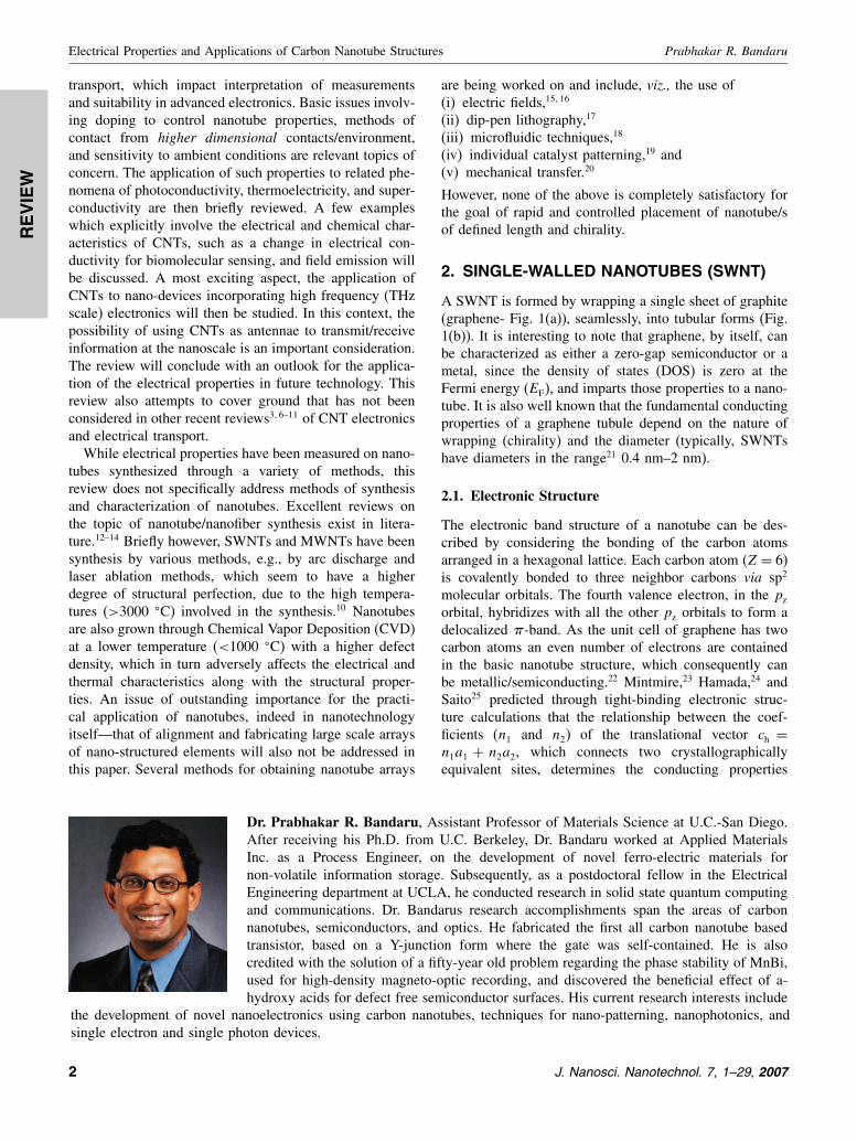
Dr. Prabhakar R. Bandaru, Assistant Professor of Materials Science at U.C.-San Diego.After receiving his Ph.D. from U.C. Berkeley, Dr. Bandaru worked at Applied MaterialsInc. as a Process Engineer, on the development of novel ferro-electric materials fornon-volatile information storage. Subsequently, as a postdoctoral fellow in the ElectricalEngineering department at UCLA, he conducted research in solid state quantum computingand communications. Dr. Bandarus research accomplishments span the areas of carbonnanotubes, semiconductors, and optics. He fabricated the first all carbon nanotube basedtransistor, based on a Y-junction form where the gate was self-contained. He is alsocredited with the solution of a fifty-year old problem regarding the phase stability of MnBi,used for high-density magneto-optic recording, and discovered the beneficial effect of a-hydroxy acids for defect free semiconductor surfaces. His current research interests include
the development of novel nanoelectronics using carbon nanotubes, techniques for nano-patterning, nanophotonics, andsingle electron and single photon devices.
are being worked on and include, viz., the use of(i) electric fields,15�16
(ii) dip-pen lithography,17
(iii) microfluidic techniques,18
(iv) individual catalyst patterning,19 and(v) mechanical transfer.20
However, none of the above is completely satisfactory forthe goal of rapid and controlled placement of nanotube/sof defined length and chirality.
2. SINGLE-WALLED NANOTUBES (SWNT)
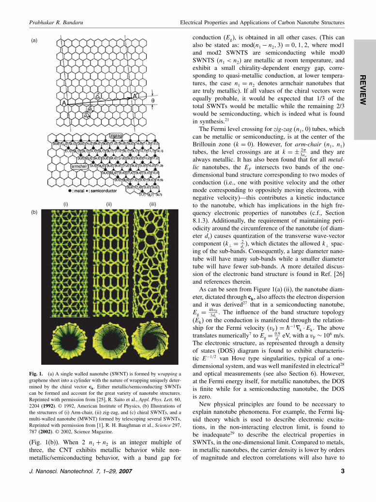
A SWNT is formed by wrapping a single sheet of graphite(graphene- Fig. 1(a)), seamlessly, into tubular forms (Fig.1(b)). It is interesting to note that graphene, by itself, canbe characterized as either a zero-gap semiconductor or ametal, since the density of states (DOS) is zero at theFermi energy (EF), and imparts those properties to a nano-tube. It is also well known that the fundamental conductingproperties of a graphene tubule depend on the nature ofwrapping (chirality) and the diameter (typically, SWNTshave diameters in the range21 0.4 nm–2 nm).
2.1. Electronic Structure
The electronic band structure of a nanotube can be des-cribed by considering the bonding of the carbon atomsarranged in a hexagonal lattice. Each carbon atom (Z = 6)is covalently bonded to three neighbor carbons via sp2
molecular orbitals. The fourth valence electron, in the pz
orbital, hybridizes with all the other pz orbitals to form adelocalized �-band. As the unit cell of graphene has twocarbon atoms an even number of electrons are containedin the basic nanotube structure, which consequently canbe metallic/semiconducting.22 Mintmire,23 Hamada,24 andSaito25 predicted through tight-binding electronic struc-ture calculations that the relationship between the coef-ficients (n1 and n2) of the translational vector ch =n1a1 + n2a2, which connects two crystallographicallyequivalent sites, determines the conducting properties
2 J. Nanosci. Nanotechnol. 7, 1–29, 2007
REVIEW
Prabhakar R. Bandaru Electrical Properties and Applications of Carbon Nanotube Structures
(b)
(i) (ii) (iii)
(a)
Fig. 1. (a) A single walled nanotube (SWNT) is formed by wrapping agraphene sheet into a cylinder with the nature of wrapping uniquely deter-mined by the chiral vector ch. Either metallic/semiconducting SWNTscan be formed and account for the great variety of nanotube structures.Reprinted with permission from [25], R. Saito et al., Appl. Phys. Lett. 60,2204 (1992). © 1992, American Institute of Physics, (b) Illustrations ofthe structures of (i) Arm-chair, (ii) zig-zag, and (c) chiral SWNTs, and amulti-walled nanotube (MWNT) formed by telescoping several SWNTs,Reprinted with permission from [1], R. H. Baughman et al., Science 297,787 (2002). © 2002, Science Magazine.
(Fig. 1(b)). When 2 n1 + n2 is an integer multiple ofthree, the CNT exhibits metallic behavior while non-metallic/semiconducting behavior, with a band gap for
conduction (Eg), is obtained in all other cases. (This canalso be stated as: mod(n1 − n2�3� = 0�1�2, where mod1and mod2 SWNTS are semiconducting while mod0SWNTS (n1 < n2) are metallic at room temperature, andexhibit a small chirality-dependent energy gap, corre-sponding to quasi-metallic conduction, at lower tempera-tures, the case n1 = n2 denotes armchair nanotubes thatare truly metallic). If all values of the chiral vectors wereequally probable, it would be expected that 1/3 of thetotal SWNTs would be metallic while the remaining 2/3would be semiconducting, which is indeed what is foundin synthesis.21
The Fermi level crossing for zig-zag (n1, 0) tubes, whichcan be metallic or semiconducting, is at the center of theBrillouin zone (k = 0). However, for arm-chair (n1, n1)tubes, the level crossings are at k = ± 2�
3aoand they are
always metallic. It has also been found that for all metal-lic nanotubes, the EF intersects two bands of the one-dimensional band structure corresponding to two modes ofconduction (i.e., one with positive velocity and the othermode corresponding to oppositely moving electrons, withnegative velocity)—this contributes a kinetic inductanceto the nanotube, which has implications in the high fre-quency electronic properties of nanotubes (c.f., Section8.1.3). Additionally, the requirement of maintaining peri-odicity around the circumference of the nanotube (of diam-eter dt) causes quantization of the transverse wave-vectorcomponent (k⊥ = 2
dt), which dictates the allowed k⊥ spac-
ing of the sub-bands. Consequently, a large diameter nano-tube will have many sub-bands while a smaller diametertube will have fewer sub-bands. A more detailed discus-sion of the electronic band structure is found in Ref. [26]and references therein.
As can be seen from Figure 1(a) (ii), the nanotube diam-eter, dictated through ch, also affects the electron dispersionand it was derived27 that in a semiconducting nanotube,Eg = 4�vF
3dt. The influence of the band structure topology
(Ek) on the conduction is manifested through the relation-ship for the Fermi velocity (vF� = �
−1�k ·Ek. The abovetranslates numerically7 to Eg = 0�9
dteV, with a vF ∼ 106 m/s.
The electronic structure, as represented through a densityof states (DOS) diagram is found to exhibit characteris-tic E−1/2 van Hove type singularities, typical of a one-dimensional system, and was well manifested in electrical28
and optical measurements (see also Section 6). However,at the Fermi energy itself, for metallic nanotubes, the DOSis finite while for a semiconducting nanotube, the DOSis zero.
New physical principles are found to be necessary toexplain nanotube phenomena. For example, the Fermi liq-uid theory which is used to describe electronic excita-tions, in the non-interacting electron limit, is found tobe inadequate29 to describe the electrical properties inSWNTs, in the one-dimensional limit. Compared to metals,in metallic nanotubes, the carrier density is lower by ordersof magnitude and electron correlations will also have to
J. Nanosci. Nanotechnol. 7, 1–29, 2007 3

REVIEW
Electrical Properties and Applications of Carbon Nanotube Structures Prabhakar R. Bandaru
be considered. Consequently, the Luttinger liquid (LL) the-ory, which does take into account electron-electron inter-actions is more appropriate and can be embodied in novelphenomena30 such as spin-charge separation, suppressionof the electron tunneling density of states and interactiondependent power laws for the electrical conduction. In mostexperimental studies, however, the details of such behav-ior are masked by imperfect contacts and contact resis-tances. Theoretically, a g parameter which is the ratio ofthe single-electron charging energy to the single parti-cle energy spacing is quoted for monitoring the degreeof LL behavior in a one-dimensional system. In the non-interacting Fermi liquid case, g = 1, whereas interactionsreduce the value of g. In SWNTs, g has been estimated tobe in the range of ∼0.2–0.3.30 An experimental confirma-tion of such behavior in nanotubes/nanotube ropes31 hasbeen obtained through the power law dependence of theconductance (G) on voltage (V ), i.e., G�V 0�36 and tem-perature (T ), i.e., G�T 0�3−0�6. Further experimental con-firmation of the LL behavior can also be made throughtunneling experiments between two SWNTs.32
It is to be kept in mind, however, that the LL descrip-tion strictly applies to metallic SWNTs33 (Interestingly, ithas been predicted34 that in bundles of metallic SWNTsvan der Waals interaction between individual nanotubescan induce a pseudo-gap of ∼0.1 eV, which mimics semi-conducting behavior).
2.2. Doping Characteristics of Nanotubes
For semiconducting SWNTs, in the absence of impuritiesor defects (doping), the Fermi energy (EF) is taken to be ata reference value of zero. However, for a realistic graphenebased nanotube a finite doping is inevitable due to thepresence of adsorbates, from the ambient, which wouldcause charge transfer. In that case, the EF is either <0(for hole doping, electron transfer from the NT—p type)or >0 (for electron doping, electron transfer to the NT—n type). The effects of temperature also have to be takeninto consideration i.e., (i) kBT >EF or (ii) kBT <EF, (alsosee section 2.3). Case (i), suitable for high temperatures,corresponds to low doping while low temperatures (case(ii)) are typify strong doping conditions. In metallic nano-tubes the results of the shifts in the Fermi level are maskedby a higher density of states and doping effects are lessmarked.
When connected to external contacts, semiconductingSWNTs are usually measured to be p-type. This character-istic could be induced by the higher work function of thecontact35 whereby holes could be generated in the nano-tube due to electron transfer from the NT to the contact.However, it was seen, in top-gated device structures with afield effect transistor (FET) configuration, that devices canshow ambipolar characteristics36 with larger drive currents.The device characteristics are then determined by the rel-ative heights of the Schottky barrier for electron- and hole
injection at the metal electrode-CNT interface. It was alsodetermined37 that the annealing in vacuum, through oxy-gen removal (or doping the surface with alkali metals) con-verts p-type devices to n-type, which results in a shift inthe Fermi energy from the valence band to mid-gap. Inter-estingly, exposure to oxygen resulted in reversion to p-typecharacteristics. Evidence for charge transfer in doped car-bon nanotube bundles exposed to electron donor (K, Rb)and electron acceptor (Br, I) atoms was also seen throughRaman spectroscopy investgations38 through a vibrationalmode shift.
As mentioned earlier, it is seen that intrinsic nanotubescannot be produced whenever there is exposure to oxygenambients. The effect of oxygen on nanotubes is plausiblynot just due to doping, as is conventionally understood butcould be related more to the effects on the contacts. Also,the physisorbtion39 of the oxygen with CNTs is weak andis unlikely to result in charge transfer. A phenomenologi-cal model was advanced to explain the p- to n-conversion(Fig. 2), where the concentration of oxygen is proportionalto, and determines the position of, the EF at the metal-CNTinterface. Such an effect changes the line-up of the bandsat the interface but does not involve the bulk of the CNT.
Fig. 2. Effect of ambient conditions on the electronic band structure ofa CNT-metal contact. Initially, (a) the doping is p-type due to the higherwork function of the metal and extrinsic oxygen doping, (b) When oxy-gen is driven out through an annealing treatment, the transistor behaviormimics a n-doped device in that electron injection is allowed, but (c) truen-type behavior is only obtained through alkali element (e.g., K) doping,(d) At higher doping levels, electron tunneling occurs through a thin bar-rier. Reprinted with permission from [37], V. Derycke et al., Appl. Phys.Lett. 80, 2773 (2002). © 2002, American Institute of Physics.
4 J. Nanosci. Nanotechnol. 7, 1–29, 2007

REVIEW
Prabhakar R. Bandaru Electrical Properties and Applications of Carbon Nanotube Structures
When EF at the junction is close to the center of the bandgap, the barrier allows tunneling and ambipolar transportis observed. With Au contacts in air, only holes can beinjected into the device, while annealing/removal of oxygenresults in only electrons being injected due to the high holeinjection barriers (Fig. 2(b)). Subsequently exposing theSWNTs to nitrogen40 and alkali metal dopants37 resultedin n-doping. However, in the latter case the strong oxidiz-ing characteristics of the dopants are undesirable and stabledoping can instead be obtained through functionaliza-tion by amine-rich polymers12 such as polyethyleneimine(PEI).
Note that in a SWNT fabricated as a p-n junction, thedepletion region is a dipole ring, c.f., as opposed to adipole sheet in a planar junction.41 Consequently, thedepletion width (W ) of a nanotube device at low dopinglevels is found to depend exponentially on the inverse dop-ing fraction (f ).42 This factor needs to be considered indevice design, where tunneling through the device occursat f > 2 ·10−3 while in the opposite case, i.e., f < 2 ·10−4,a large depletion width is formed. Even outside the deple-tion region, the charge distribution is not cut-off abruptly,but has a logarithmic decay with distance z (as 1
ln�z/�� ,where � is a constant proportional to the nanotube radius)and can extend up to m distances. These limitations oncharge confinement are intrinsic to nanotubes and demanda radical new design for devices. One might need to con-trol the leakage current (in highly doped nanotube basedp-n junctions, due to the large charge decay lengths) byincluding an undoped region of length (L) W ) betweenthe p- and n-doped regions. This reduces the tunnelingprobability, and hence the leakage current, by an exponen-tial factor, ∼ exp�−2kL�.
In summary, the mechanisms for doping and the deter-mination of the acceptor and donor levels still need tobe investigated. Raman spectroscopy, widely used fordetermining the metallic/semiconducting characteristics ofnanotubes,43 offers one possible way to determine thecharge transfer characteristics through spectroscopic lineshifts.38�44 Charged defects are also known45 to modifyelectronic properties through local modification of theelectronic structure (see also Sections 7.2 and 7.3(a)).
2.3. Characteristics of Electrical Transport
A determination of the band structure allows for the cal-culation of an energy dependent Drude conductivity ("2D)for the graphene sheet that constitutes a nanotube surface,as = � 2e2
h� E�vFle. The elastic scattering length (le) of the
carriers is proportional to the electron-phonon scatteringand generally increases with decreasing temperature (usu-ally, le� T−p, with p > 1). One characterizes the electricalconductivity in two regimes:(1) Low temperatures (kBT < EF), where in the conduc-tivity equation above, the energy (E) replaced by EF (theFermi energy). The conductivity in this regime is metallic.
A finite zero-temperature value, the magnitude of which isdetermined by the static disorder, is obtained.(2) High temperatures (kBT > EF ), where in the conduc-tivity equation, the energy (E) is replaced by kBT . Theconductivity, and the carrier density, is then directly pro-portional to T .
At the very outset, it is not trivial to measure the intrin-sic resistance of a SWNT. Any contact in addition to thoseat the two ends of the tube (say, for a four-terminal mea-surement) can destroy46 the one-dimensional nature of theSWNT and make a true interpretation difficult. Theoreti-cally, for a strictly one-dimensional system the Landauerformula predicts an intrinsic resistance (Ro
int), indepen-dent of the length, to be equal to h
e21
T �EF�which translates
to a resistance of 25.8 k() assuming perfect transmis-sion through ideal Ohmic contacts, i.e., T �EF� equal toone. This contact resistance arises from an intrinsic mis-match between the external contacts to the wire (which areof higher dimensionality) and the one-dimensional nano-tube system and is always present. When one takes indi-vidually into account both the two-fold spin and banddegeneracy of a nanotube the intrinsic resistance (Rint)now becomes h
4e21
T �EF �, which again seems to be length
independent.However, in the above discussion, we have not yet con-
sidered the contribution of the external contacts. When weconsider the transmission (T ) through the contacts into theone-dimensional channel and then to the next contact, T =le
le+L , where le is the mean free path length for scattering46
and L is the length of the one-dimensional conductor. Theresistance is now equal to
h
4e2
le +Lle
≡ h
4e2
(1+ le
L
)The first term represents Rint while the second termdenotes an Ohmic resistance (ROhmic) associated with scat-tering. In the presence of dynamically scattering impu-rities, such as acoustical or optical phonons, which areinevitably present at any temperature above 0 K, theOhmic resistance should definitely be considered. It isinteresting to consider the limiting cases of a large meanfree path (le → ) or a small tube (L→ 0) i.e., in the bal-listic regime, when the Ohmic resistance is seen to vanish.Finally, the material resistance of the contacts contributesan additional term: Rc. The total resistance as measured inan external circuit would now be: R = Rint +ROhmic +Rc.These considerations imply that a minimum resistance ofh
4e2 (∼6.5 k() is present in a SWNT with a single chan-nel of conduction. In practice however, imperfect contacts(which lead to T < 1) and the presence of impurities leadto larger resistance values, while deviations from strictone-dimensionality or multiple channels of conduction (asin a MWNT) could lead to smaller numbers for the resis-tance. These observations primarily account for the largediscrepancy of the numerical value of the resistances inliterature.
J. Nanosci. Nanotechnol. 7, 1–29, 2007 5

REVIEW
Electrical Properties and Applications of Carbon Nanotube Structures Prabhakar R. Bandaru
2.4. Experimental Measurements
For measuring the electrical properties, standard lithogra-phic47 practices are employed. A solution of SWNT ropes,dispersed in an organic solvent (e.g., dichloroethane), isspun onto an oxidized Silicon wafer. The nanotube is thenaligned on to the electrodes (Source and Drain) eitherthrough Atomic Force Microscope (AFM) manipulation orelectron-beam lithography alignment. Experiments are thentypically carried out, in a three-terminal geometry (mim-icking a FET—Field Effect Transistor topology) utilizingthe Silicon wafer as a back-gate. Further details of experi-mental procedures are illustrated in Ref. [11].
The metallic/semiconducting characteristics of individ-ual nanotubes are ascertained by the absence or depen-dence of the source-drain current-voltage characteristicson the gate voltage. While the smallest possible resistanceof SWNTs is ∼6.5 k(, high contact/Ohmic resistancesusually prevent the observation of such values. The gran-ularity of the metal electrodes and contamination at theinterface are some obstacles to the realization of good con-tacts. Several methods such as thermal and electron-beaminduced annealing48 are being attempted with moderatesuccess. Early experimental results35 on the I–V character-istics of semiconducting SWNTs (indicative of p-doping)in a FET like arrangement are shown in Figure 3. Thepinning of the valence band of the nanotube to the Fermilevel of the contact metal electrode (typically Au) resultsin the description of transport in the channel of the deviceas through two back-to-back connected Schottky barri-ers. The device operation can be explained by invokingband structure modification typical of a traditional semi-conductor transistor.41 The observed gain, in this case,
Fig. 3. Current–Voltage (I–Vbias) curves as a function of gate voltage(Vgate) reveal p-type characteristics for an SWNT arranged in a FET con-figuration (see top-left inset) The applied bias is across the source anddrain electrodes (Vbias) and Vgate is applied on the backside of the FET. Thedecrease of the conductance (G) with increasingly positive Vgate (bottom-right inset) varies by six orders of magnitude and is characteristic ofholes as majority carriers. Reprinted with permission from [35], S. J.Tans et al., Nature 393, 49 (1998). © 1998, Nature Magazine, MacmillanPublishers.
was only ∼0.35 but could be increased by reducing thegate oxide thickness/using high *-dielectrics.49 The carriermobility ( ) can be determined from the (I–Vbias�Vg data7
through
G= C ′g�Vg −Vgo�
L
where C ′g is the capacitance per length (L) of the tube,
and Vgo is the threshold voltage. Owing to the nanotube-metal band alignment, it was found that the p-type (hole)conductance in nanotube FETs is higher than n-dopedchannels (electrons as majority carriers). While in theearly experiments, hole mobilities of ∼200 cm2/Vs wereobserved,50 recent work51 on longer nanotubes reportmobilities exceeding 10,000 cm2/Vs. Additionally, withPd/Pt contacts, and in situ modification of the electrodework function through hydrogen annealing treatments,52
Ohmic behavior has been induced with ballistic transportand measured nanotube resistance approaching the theoret-ical minimum of Ro�= h
4e2 �. Such behavior, characteristicof reflection less contacts, were used to construct deviceswith perfect electron coherence, such as a Fabry-Perotinterferometer.53
Further seminal work focused on low temperature trans-port in SWNTs, where non-linear transport characteristicssuch as Coulomb Blockade effects were observed.54�55 Inthis regime (kBT < EF), the nanotube is essentially behav-ing like a single-electron island (c.f., quantum dot)/arrayof islands, of very small capacitance (aF, ∼10−18F ) wherethe addition of each extra electron results in an enormouscharging energy �= e2
2C � cost. A peak in the conductancecorresponding to the addition of each extra electron hasbeen observed as a function of the gate voltage56 (Fig. 4).Further details of such experiments for observing quantumdot like behavior are found in Refs. [54, 57, 58], Suchwork has served to elucidate the nature of transport innanotubes vis-à-vis resonant tunneling from the electrodesto discrete energy levels in the nanotubes and the coher-ence of electron currents, at low temperatures. However,significant deviations from the simple Coulomb blockadepicture are mediated through the electronic correlations59
Fig. 4. Sharp spikes in the conductance (G), characteristic of Coulombblockade and single electron tunneling, is seen in electrical transportthrough a SWNT as the gate voltage (Vg) is varied. Reprinted with per-mission from [56], J. Nygard et al., Appl. Phys. A 69, 297 (1999). © 1999,Springer-Verlag.
6 J. Nanosci. Nanotechnol. 7, 1–29, 2007

REVIEW
Prabhakar R. Bandaru Electrical Properties and Applications of Carbon Nanotube Structures
and imperfect screening due to Luttinger liquid behav-ior (Section 2.1), where it is found (at <5 mK) that anapplied gate voltage significantly changes the electronicspectrum through inducing spin flips. The transport mea-surements, in a magnetic field, can help in the determina-tion of the ground-state spin configuration and a need fora better model than simple Coulomb Blockade is felt. TheZeeman energy splitting (= g BB� was used60 to deter-mine the gyromagnetic ratio (g) to be ∼2.04 indicatingthe absence of orbital contributions. The ground state ofa short SWNT, exhibiting quantum dot like characteris-tics, was hypothesized60 to alternate between the S = 0and S = 1/2 states. These results are in contrast to thoseof Tans59 et al. where it was stated that electrons enterthe nanotube with the same spin (with a unique S), at lowfields. These observations indicate that studies beyond thesingle electron picture are imperative to describe the lowenergy electron transport in SWNTs.
It was also found through scanning probe techniques61
that semiconducting nanotubes had significant potentialfluctuations along the length of the nanotube, more so thanin the case of metallic nanotubes. This is equivalent tobreaking the nanotube into a series of quantum dots and isparticularly insidious to the conductance of semiconduct-ing SWNTs. If the disorder is long-range, the difference inthe transport characteristics between semiconducting andmetallic tubes could be explained, and lead to much largermean free paths (>1 m) in the latter variety.62
3. MULTI-WALLED NANOTUBES (MWNT)
MWNTs are composed of coaxial nanotube cylinders, ofdifferent helicities, with a typical spacing of ∼0.34 nm,27
which corresponds closely to the inter-layer distance ingraphite of 0.335 nm.21 These adjacent layers are gener-ally non-commensurate (different chiralities) with a neg-ligible inter-layer electronic coupling and could alternaterandomly63�64 between metallic and semiconducting vari-eties. The layers, constituting the individual cylinders, arefound to close in pairs at the very tip of a MWNT, and thedetailed structure of the tips plays an important role, sayin the electronic and field emission65 properties of nano-tubes. While there was debate on whether the individualnanotubes close on themselves or the tubes are scrolled,it is currently accepted through the evidence of high res-olution electron microscopy studies66 that the latter i.e.,the Russian doll model is more likely to be true. Typi-cal MWNT diameters grown by the arc-discharge methodare ∼20 nm, while CVD grown nanotubes can have muchlarger diameters of up to 100 nm. (In literature, a widevariety of filamentous/segmented/non-continuous carbonnanostructures are often classified under the category ofnanotubes, but which should really be called nanofibers14)Larger diameter tubes are found to have a greater densityof defects, i.e., vacancies or interstitials.
3.1. Electronic Structure
As MWNTs are composed of several coaxial SWNTs itmight be expected that they are not strictly one-dimensionalconductors. However, a pseudo-gap was observed67 in I–Vmeasurements with a power scaling law for the conduc-tance, characteristic of Luttinger liquid (Section 2.1) likebehavior. It has been found that the LL parameter g scalesas
√N , where N is the number of tubules screening the
charge in the MWNT. It was also determined68 (see alsoSection 3.3.1) that the current flow only occurs through theouter most nanotube cylinder (which could also result fromthe contact geometry with deposited metal electrodes).Consequently, many features peculiar to reduced dimen-sionality can be studied in MWNTs as well. Also, while themutual interaction between the adjacent coaxial cylindersmight be very small, it cannot be completely neglected,and which makes for a richer band structure69 in contrast toSWNTs and comparable to graphite (where the inter-planecoupling is ∼10 meV). Inter-tube coupling (which dependsinversely with the MWNT diameter70) can also signifi-cantly affect the band structure. For instance, in a two wallnanotube, one metallic and the other semiconducting lowenergy properties characteristic of metallic tubes predom-inate while if both the constituent tubes are metallic, amuch more complicated situation in terms of band cross-ings can arise. As an example, it was shown that71 in an-wall armchair nanotube n2 avoided band crossing canoccur leading to the formation of pseudo-gaps in the den-sity of states. The consequent strong coupling between theelectronic states at the Fermi level (EF) and the phononmodes may then cause superconductivity.71 Additionally,27
strong band structure modifications can also be expectedif the constituent undoped nanotubes were of different chi-ralities. However, in the case of different chiralities (say,arm-chair and zig-zag) the total DOS would just be thesum of the individual density of states.
3.2. Transport Characteristics
The electrical conductivity of MWNTs can be modeled tobe comparable with that of independent graphene sheets.When the tube diameter (dt) is smaller than the elasticmean free path (le), the one-dimensional ballistic transportpredominates, while, if dt is larger than le, the current flowcould be described as diffusive/two-dimensional transport.Another quantity of importance46 is the phase coherencelength (l.) which was determined, through an elegantexperiment68 exploiting the Aharonov-Bohm effect, to be∼250 nm, even larger than the diameter of the MWNT!However, the value of l. inferred from direct I–V mea-surements was ∼20 nm; the discrepancy could arise frompoor Ohmic contacts. Another source of difference couldalso be due to the quality of the MWNTs; higher tempera-ture growth processes (say, arc-growth) synthesize cleanerMWNTs and exhibit metallic temperature dependence,
J. Nanosci. Nanotechnol. 7, 1–29, 2007 7

REVIEW
Electrical Properties and Applications of Carbon Nanotube Structures Prabhakar R. Bandaru
where the resistance linearly decreases with tempera-ture. Coulomb Blockade effects, which are almost alwaysobserved in SWNTs at low temperatures, do not seem tobe particularly relevant for MWNTs.
Quantized conductance, corresponding to multiples ofGo ( 2e2
h) and ballistic transport, was measured,72 at room
temperature, in a single MWNT mounted on a scanningprobe microscope (SPM) tip and dipped into liquid mer-cury metal. While a conductance of 2Go should havebeen observed in the absence of magnetic fields, it wasassumed for the interpretation of the experimental results,that the spin degeneracy was resolved through electron-lattice structure coupling. In yet another experiment, wherethe MWNT was grown in situ on a tungsten contact, forbetter contact resistance, and probed with a W tip, a con-ductance of up to 490 Go (corresponding to a current of8 mA in a 100 nm diameter MWNT) was observed,73 char-acteristic of multi-channel quasi-ballistic transport. Gen-erally, measurements of nanotubes placed on/below metalelectrode contacts on substrates suffer from non-reliableOhmic contacts—a recurring theme in electrical charac-terization. In measurements, using contacting electrodespatterned through STM lithography, it was shown74 that atlow temperatures (∼20 mK) electron interference effectstypical of disordered conductors are present in the trans-port characteristics. A logarithmic decrease of the conduc-tance with temperature followed by a saturation was takento be the evidence for two-dimensional weak localization4
effects (Fig. 5) Further evidence of localization phenom-ena is manifested through the observation of a negativemagneto-resistance (MR) and a low value (<20 nm) for
Fig. 5. The electrical conductance as a function of temperature for aMWNT exhibits an initial decrease followed by saturation at low temper-atures. Weak localization behavior is manifested at temperatures <60 K,plotted as a function of the magnetic field (B). The presence of disor-der is thought to be responsible. Reprinted with permission from [74],L. Langer et al., Phys. Rev. Lett. 76, 479 (1996). © 1996, The AmericanPhysical Society.
the l. (note that localization effects are important only inthe case, l. < dt�.
75
In doped MWNTs, the Fermi energy (EF) is shiftedchanging the total number of participating conductionchannels. Localization effects have also been observed76
in B doped MWNTs, along with a negative MR, below∼60 K. The overall temperature dependence of the con-ductance (G) is then:(i) an initial linear decrease of G from 300 K–60 K,(ii) a log (T ) variation from 60–1 K, and(iii) a saturation at low temperature (<1 K).
(It is interesting to note that in disordered graphite atlow temperatures, carrier localization leads to a resistanceincrease (with a typical sheet resistance, Rs of ∼100 k()while crystalline graphite is characterized by a metallic Rs
of ∼1 k().
3.2.1. Magneto-Resistance Measurements
Electron-electron interactions do have to be considered inexplaining the magneto-resistance (MR) measurements onnanotubes. A typical MR measurement of a MWNT in aperpendicular magnetic field67 (Schonenberger, 1999) isshown in Figure 6(a) where the fits to the lines are madeusing one-dimensional weak localization theory and theconductance change (0G� ≈ � 2e2
h�l.L
is used to calculatethe phase coherence length (l.). The strong temperaturedependence of the conductance is modeled through G�T 1,where 1 < 0�3 (In SWNTs, 1 can be as large as 0.8 dueto reduced screening effects). It was noted, with a theo-retical basis from the Onsager reciprocity relations,46 thatthe two-terminal resistance was symmetric in a magneticfield while the four terminal resistance could be asymmet-ric. Universal conductance fluctuations (UCF), of magni-tude e2
h, characteristic of stochastic, quantum interference
effects77 in the sample have also been observed in MRmeasurements. While disorder in the nanotube could causethe UCF, it is also likely that chaotic scattering of the elec-trons, in a nanotube cavity, could also be responsible.
While the weak localization effects monotonically dis-appear for the case of a perpendicular field, in contrast,a parallel magnetic field causes a periodic, (0B = � h2e �
1A�
modulation of the localization effects which is area (A)dependent—Figure 6(b). In the parallel case, the threadingmagnetic flux (.) gives rise to an Aharanov-Bohm phasewhich modifies the boundary conditions transverse tothe nanotube. From the Altshuler–Aronov–Spivak (AAS)theory68 this led to the conclusion that the current in aMWNT only traverses the outermost tubule.
In summary, the wide variety of electrical transportcharacteristics could be due to the differences in theirgrowth conditions and method of probing/contacts. Con-sequently, MWNTs display characteristics ranging fromlocalization to metallic behavior at low temperature result-ing in either a small or large phase coherence length. The
8 J. Nanosci. Nanotechnol. 7, 1–29, 2007

REVIEW
Prabhakar R. Bandaru Electrical Properties and Applications of Carbon Nanotube Structures
Fig. 6. Negative magneto-resistance (MR) is observed in a MWNTplaced perpendicular to a magnetic field. Reprinted with permissionfrom [27], L. Forro and C. Schonenberger, Physical properties of Multi-wall Nanotubes, Carbon Nanotubes—Topics in Applied Physics, editedby M. S. Dresselhaus, G. Dresselhaus, and P. Avouris, Springer-Verlag,Heidelberg, (2001). © 2001, Springer-Verlag, Berlin; (b) The magnetore-sistance of a MWNT placed parallel to a magnetic field exhibits charac-teristic (h/2e) oscillations. A phase coherence length (l.) of 200 nm hasbeen inferred. Universal Conductance Fluctuations (UCF) in the resis-tance are present, e.g., see data at 0.3 K. Reprinted with permission from[68], A. Bachtold et al., Nature 397, 673 (1999). © 1999, Nature Maga-zine, Macmillan Publishers.
non-local interactions manifest in a disordered sample cancause difficulties in the interpretation of even four-terminalmeasurements.
4. SUPERCONDUCTIVITY
A postulated mechanism of superconductivity in one-dimensional SWNTs involves the reversal of the normallyrepulsive interactions of the Luttinger liquid. This mayhappen, for instance, when the curvature78 of CNTs leads
Fig. 7. Observation of superconductivity on SWNT ropes. A Tc of∼0.5 K is inferred. The length (L2), the number of nanotubes in the bun-dle of ropes (N2) and the room temperature resistance (R2) are indicatedon the figure, along with the response to the magnetic field. Reprintedwith permission from [80], M. Kociak et al., Phys. Rev. Lett. 86, 2416(2001). © 2001, The American Physical Society.
to the creation of new electron-phonon scattering channelsand consequent attractive electron phonon interactions79
can induce superconductivity. It was also proposed thatthe superconducting transition temperature (Tc) could beenhanced by chemical doping of the nanotubes, by anal-ogy with the higher transition temperatures in alkali dopedfullerenes.
A Tc of ∼0.55 K was measured80 (Fig. 7) in ropesof SWNTs connected to non-superconducting metallic(Pt/Au) pads. From the Bardeen–Cooper-Schrieffer (BCS)relations (0 = 1�76kBTc) a superconducting gap (0)
of ∼85 eV and a coherence length (3=√��vF lmfp�/0) of
300 nm was inferred, for a mean-free path length (lmfp)of ∼18 nm and a Fermi velocity (vF) of 8 · 105 m/s. Ahigher Tc of 15 K was reported 81 in 04 nm SWNTs embed-ded in a zeolite matrix, accompanied by the observationof an anisotropic Meissner effect, characteristic to one-dimension. Such an effect is very intriguing in that a strictlyone-dimensional system is unstable to any fluctuations andtrue superconducting behavior can only be observed atT = 0 K.
It was also shown that82 superconductivity could beinduced in a metallic nanotube bundle in close proxim-ity with a superconducting electrode (Re/Ta on Au), ona characteristic length scale, bounded by both the phasecoherence length (l.) and the thermal diffusion length(lT). Induced superconductivity was inferred through theexistence of Josephson supercurrents, with a magnitudeexceeding the theoretically predicted value of �0
eRN(0 is the
superconducting gap, RN-the normal resistance of the junc-tion). To explain the observation of higher than expectedvalue of the supercurrents, it was hypothesized that thesuperconducting state in the nanotube could have been sta-bilized by the macroscopic superconductivity of the con-tacts. On the other hand, supercurrents were not observed83
in SWNTs connected to Nb electrodes; however, the trans-port behavior was seen to be dominated the effect ofthe contacts, tuned by varying a back-side gate voltage(Vg). The contacts were varied between (i) high (Vg set
J. Nanosci. Nanotechnol. 7, 1–29, 2007 9

REVIEW
Electrical Properties and Applications of Carbon Nanotube Structures Prabhakar R. Bandaru
to −40 V), and (ii) low transparency (Vg = 0 V) to incidentelectrons. At high interface transparency, characteristics ofAndreev reflection (where an incident electron at the con-tact is converted into a Cooper pair with the concomitantintroduction of a reflected hole) were noted. In the tun-neling regime, where the contacts are relatively opaqueto incident currents, the I–V behavior was comparableto SWNT attachment to non-superconducting electrodes.While the above observations do not explicitly take intoaccount electron-electron interactions, it seems necessaryto consider Luttinger liquid behavior for explaining verylow temperature (40 mK) spectra and superconducting cor-relations in one-dimension more fully.
5. THERMOELECTRIC PROPERTIES
It has been found recently84�85 that dimensional restrictioncan lead to a much enhanced efficiency over tradition-ally used bulk thermoelectrics. Nanotubes offer a naturaltemplate for exploring the effects of reduced dimension-ality towards fabricating the best thermoelectric86 mate-rial. However, in the case of intrinsic/undoped SWNTs,due to symmetry considerations, the electron and the holethermopower (S) contributions exactly cancel out and theSeebeck effect87 is not exhibited. This can also be for-mally derived from the Mott-relation, which relates S tothe density of states (DOS) at the Fermi level:
S = �2
3k2BT
e
d�DOS�EF��
dEF
In a metallic nanotube, the derivative d�DOS�EF��
dEFis zero,
which implies a zero S. It is also interesting to note that inthe case of phonon or electron ballistic transport, S→ 0.(The heat current, in analogy to an electric current, is NGT0T , where N is the total number of acoustic modes, thethermal conductance quantum88 (GT) is �2
3k2
BT
h, and 0T the
temperature difference along the nanotube). Any effectsthat break electron-hole symmetry, i.e., doping, impuritiesetc., in the nanotube can however contribute to a ther-mopower due to a larger DOS (EF), which is enhanced inlow-dimensional nanostructures.
Generally, the efficiency of a material’s thermoelectricperformance is quantified by a figure of merit (ZT), whereT is the temperature of operation, and Z�= S2"
k�. A high
ZT then, often demands that a set of incompatible crite-ria have to be simultaneously fulfilled, i.e., a high ther-mopower/Seebeck coefficient S (which is greatest forinsulators), large electronic conductivity " (indicated bymetallicity), and low thermal conductivity k (which con-sists of both the phonon contribution: klattice and anelectronic part: kelectronic). Indeed the ideal thermoelec-tric material has been described89 as a phonon-glass (lowk)-electron crystal (large "). Artificially fabricated quan-tum confined structures, say quantum wells, have shown
promise85�90–92 in this regard by increasing the S throughcarrier confinement, modulation doping which increases" and the presence of interfaces which may enhancelong wavelength phonon scattering, thus decreasing klattice
(Note that the kelectronic is proportional to " through theWiedemann-Franz law).22
Early measurements93 of the thermoelectric effects wereperformed in mats of nanotubes (of both metallic and semi-conducting variety) where the breaking of the electron-holesymmetry, for the observed thermopower, was ascribed tointer-nanotube interactions (which again, can enhance theDOS94). As mentioned earlier (section 2.1) a pseudo-gapof 0.1 eV can be opened up through these interactionsand was confirmed through an increase of the resistivity ofthe nanotube bundles at low temperature. (It is also pos-sible that weak metallic links between the nanotubes arecontributing to the measured S). The thermopower, mea-sured, was proportional to the temperature, with a value of+60 V/K at 300 K (Fig. 8), and tended to zero at low tem-peratures (cf., commercially used Bi2Te3 thermoelectricshave an S of ∼250 V/K ) The holes, typical of p-dopednanotubes, were the responsible carriers, as the sign ofthermopower follows the sign of the dominant carrier. Itwas also assumed that the EF is considerably shifted intothe valence band. Slightly higher thermopower (S) val-ues of up to 80 V/K were obtained on measurements94
on carbon nanotubes, where the Kondo resonance effect(manifested through a resistance minimum at ∼40–300 K,dependent on the catalyst particle) was thought to be amediating factor. The interaction of the Fe, Co, and Ninanoparticles, inevitably present during catalytic synthesis,with the electron spins in the nanotubes was hypothesizedto be playing a role in enhancing " , S and the thermoelec-tric efficiency. To overcome the uncertainties associatedwith the above measurements, such as inter-nanotube andsubstrate interactions, experiments were also carried out
Fig. 8. The variation of the thermopower with temperature for threedifferent SWNT samples Reprinted with permission from [93], J. Honeet al., Phys. Rev. Lett. 80, 1042 (1998). © 1998, The American PhysicalSociety.
10 J. Nanosci. Nanotechnol. 7, 1–29, 2007

REVIEW
Prabhakar R. Bandaru Electrical Properties and Applications of Carbon Nanotube Structures
on individual suspended CNTs.95�96 In this case a linearvariation of the S with temperature was seen along witha two orders of magnitude increase in the measured ther-mal conductivity over bulk/mat samples. The modulationof the conductance and the thermoelectric power, throughan external gate voltage, with a peak S of 260 V/K atroom temperature was also accomplished97 on individualSWNTs.
It is to be noted, for calculating the thermoelectric effi-ciency ZT, that there is a wide discrepancy in the mea-sured values of the thermal conductivity, ranging from20 W/mK in MWNT mats98 to 3000 W/mK (compa-rable to the in-plane thermal conductivity of graphite)in suspended nanotubes96 at room temperature. Thesenumbers are much lower than the theoretically expectedvalue99 of 6600 W/mK (due to decreased phonon scatter-ing in one-dimension) and correspondingly give a largerange of the performance efficiency: ZT at T = 300 Kranges between 0.3–3. (It is commonly accepted that aZT > 1 would compete with existing thermoelectric mate-rials and ZT > 4 would be necessary to simulate tech-nology replacement in devices such as heat pumps andpower generators). However, note that in measurements onnanotubes the traditional view of thermal conductivity, asderived from Fourier law of heat conduction, may have tobe modified100 due to the inherent assumptions of diffusivetransport. In view of the proposed utility of nanotube com-posites for thermal management,101 the investigation of thethermoelectric properties of nanotubes towards applicationin current generation and heat recovery is one of the excit-ing directions in nanotube technology. A scientific motiva-tion also arises from the theoretical interpretation that thebest thermoelectric86 is one with a delta function DOS,102
which is eminently satisfied in the band structure spectrumof nanotubes (see Sections 2.1 and 6).
6. PHOTOCONDUCTIVITY ANDLUMINESCENCE
CNTs have a direct band gap and their optical spectrahave been interpreted in terms of transitions between free-particle � and �∗ bands. The confinement of the electronicstates in a one-dimensional system also results in vanHove singularities in the nanotube density of states (DOS)which can be accessed by resonant photons of the appro-priate energy (these singularities can occur in both metallicand semiconducting nanotubes).103 A resonant enhance-ment due to the divergent nature of the singularities104 canthen be exhibited (Each type of (n1, n2) nanotube exhibitsa different set of van Hove singularities due to the geome-try of wrapping and a different set of electronic transitionenergies, which can hence be used as a diagnostic tech-nique such as Raman Spectroscopy.44)
There is a strong anisotropy of optical absorption andemission due to antenna-like interactions105 (where the size
of the nanotubes compares with the wavelength of inci-dent light), and the optical transitions induced by the lightparallel to the long nanotube axis is orders of magnitudestronger than the intensity of the transitions perpendicu-lar to the axis. The difference between parallel and per-pendicular exposure of the nanotubes to light was notedas being similar to that of planar graphite. The selectionrules for the photon transitions depend on the excitinglight polarization and are derived from group theory.104
For light polarized parallel to the nanotube axis, onlydipole-transitions from the valence band to the conductionband of the same symmetry (labeled as an En→n transi-tion, where the E refers to doubly degenerate levels) areallowed. In the case of light polarized perpendicular to thenanotube axis, only the En→n±1 transitions are permitted.Circularly polarized light propagating along the SWNTaxis can be used to probe the chirality (which is manifestedin terms of the relative intensity of the En→n+1 and theEn→n−1 transitions). Raman spectroscopy measurements106
have also been used to measure various sub-band ener-gies and quantitatively determine metal and semiconduct-ing SWNT band energies. The dielectric response �4 =41 + i42 of oriented nanotube films have been determinedthrough ellipsometry.107
A strong confinement between photo-excited electronsand holes, in low dimensional structures can createstrongly bound excitons with an increased binding energy(EB). A variational approach was used to determine108 thatthere is a significant enhancement in the EB with a powerlaw dependence (Fig. 9) on the nanotube radius (r) follow-ing r−0�6. It was also concluded that the optical transitionenergy can be lowered by as much as 40% and excitonsprovide a strong correction to the CNT electronic ener-gies. Experimental evidence for excitonic states have been
Fig. 9. The variation of the exciting binding energy (E) as a functionof the nanotube radius. A significant enhancement factor up to a factorof ten, due to confined excitons in one-dimension, is predicted for smalldiameter semiconducting nanotubes. The inset shows the spatial extentof the exciton wave function (k and q refer to the variational parametersused and are related to the exciton radius). Reprinted with permissionfrom [108], T. G. Pedersen, Phys. Rev. B 67, 073401 (2003). © 2003,The American Physical Society.
J. Nanosci. Nanotechnol. 7, 1–29, 2007 11

REVIEW
Electrical Properties and Applications of Carbon Nanotube Structures Prabhakar R. Bandaru
obtained through laser excitation.109�110 The observation109
of an additional peak in the absorption spectra (∼190meV) above the expected E22 van Hove transition wascorrelated to excitons and exciton-phonon coupling. Thewidth of the peak was related to exciton dispersion effects.In the latter experiment with pump-probe spectroscopy,110
a Mott transition indicating a highly correlated exciton gaswas indicated.
In examining the effects of illumination, excitationsintrinsic to the nanotube should be carefully distinguishedfrom photodesorption effects. For example, it has beenshown111 that UV light (∼254 nm) can desorb oxygenmolecules bound on nanotube surfaces at light intensitiesas small as 20 W/cm2. As oxygen functions as an elec-tron acceptor/hole donor in nanotubes (see Section 2.2), itsremoval lowers the hole concentration in p-type SWNTsand reduces the electrical conductivity. It has been sugges-ted that such a molecular desorption process could also bemediated through photo-excited plasmons. The hot elec-trons/holes from the plasmon de-excitations attach on tothe adsorbed molecules and induce desorption.
Fluorescence, with a quantum yield of 10−3 and a life-time of 2 ns, between singlet excitonic levels has beenobtained from isolated SWNTs.112 However, photolumi-nescence (PL) was not observed112 for SWNT bundles,possibly due to rapid charge transfer in between the nano-tubes, which allows rapid relaxation of the photo-excitedcarriers. To guard against such effects and measure the trueresponse both (1) photoconductivity109�113 and (2) elec-troluminescence (EL)114�115 experiments were carried outon single CNT constituted FETs with an oxide cappinglayer.113
To measure the photoconductivity, a nanotube transistorwas nominally operated113 in the OFF state to minimizethe dark current background and noise level. A linearlypolarized, CW Ti: Sapphire laser that is continuously tun-able between 780 nm (1.59 eV) and 980 nm (1.27 eV),with a power density of 1 kW/ m2 was shone on the nano-tube. A peak in the photocurrent corresponding to a E22
transition was observed as the incident energy was var-ied (Fig. 10(a)). The photocurrent depends strongly on thelight polarization direction, with a maximum when thelight is polarized in the direction of the nanotube axis(Fig. 10(b)) and a minimum in the perpendicular direction.A quantum efficiency of 10% was inferred through finiteelement analysis.
A CNT FET with thin Schottky barriers at the Sourceand Drain electrodes (Fig. 11(a)) can allow the simultane-ous injection of electrons and holes which permits the con-struction of a light-emitting device without the necessityof doping (or creating a p-n junction). This principle wasused114 in an ambipolar nanotube FET, where the gate wasbiased exactly in between the source and the drain i.e., thesource electrode was grounded (i.e., Vs = 0), the gate (Vg)was placed at +5V and the drain (Vd) at +10 V. This cre-ates electric fields of opposite signs at the source and drain
(a)
(b)
Fig. 10. (a) Light induced photocurrents in nanotubes, as a function ofincident photon energy. Both the experimental data and the Lorentzianfits are shown (b) The light emission varies with the angle of polariza-tion, with a maximum when the light is polarized in the direction of thenanotube axis. The photocurrent for parallel excitation is twice greaterthan that for perpendicular excitation. As a function of the polarizationangle. Reprinted with permission from [113], M. Freitag et al., Nanolett.3, 1067 (2003). © 2003, The American Chemical Society.
electrodes, and there is an equal injection of electrons (n-type modulation) from one end and holes (p-modulation)from the other. This is also equivalent to creating a for-ward biased p-n junction. The band diagram is shown inFigure 11(b) as a function of nanotube length. It was seenthat the nanotube operated as a source of linearly polar-ized infra-red emission (<1500 nm), with a peak intensityat Vg = VD/2 (Fig. 11(c)). When this bias condition wasnot satisfied, i.e., with unipolar operation no IR emissionwas observed precluding thermal effects from contribut-ing to the observed emission. The EL also depends on thelength of the nanotube, through the interplay of the phononscattering time and the carrier transit time. For example,in short (∼0.5 m) CNTs the acoustic phonon scattering(of time scale ∼0.4 ps) is too slow and only the opti-cal phonons (0.02 ps) contribute to carrier thermalizationduring the transit time of ∼0.6 ps. On the other hand, inlonger CNTs (>10 m, say) the transit time is ∼60 psand complete carrier relaxation is obtained. Consequently,the emission spectra are narrower from shorter nanotubes.These effects are especially important in high electric fieldtransport,116 where phonon assisted radiative recombina-tion can play a major role in the overall luminescence.
12 J. Nanosci. Nanotechnol. 7, 1–29, 2007

REVIEW
Prabhakar R. Bandaru Electrical Properties and Applications of Carbon Nanotube Structures
(a)
(b)
(c)
(d)
Fig. 11. (a) A typical device topology, comprising an ambipolar SWNT,for measurement of the optical properties of nanotubes, (b) The bandstructure of the device is comprised of two back-to-back Schottky diodes,through which electrons and holes are simultaneously injected for recom-bination and optical emission. Note that the band curvature is moremarked for a shorter tube (LNT = 400 nm) compared to a larger tube(LNT = 800 nm). This has implications in whether a particular SWNTis optimized for light emission/photovoltage generation (see text) (c) theobserved optical emission is localized as illustrated in the infra-red image,Reprinted with permission from [114], J. A. Misewich et al., Science300, 783 (2003). (d) A larger intensity of light emission can be obtainedby inducing electroluminescence in suspended nanotubes. The abruptjunction between a contact and a suspended SWNT causes hot electronformation and subsequent radiative exciton decay. Reprinted with per-mission from [115], J. Chen et al., Science 310, 1171 (2005). © 2005,Science Magazine.
It is interesting to compare113 the CNT band structureneeded for photovoltage generation and operation as a lightemitting device for ambipolar operation. In both cases, thecarrier tunneling through the Schottky barriers are impor-tant. In the case of photovoltage generation, the barriershould be opaque to electrons and holes and a large elec-tric field at the center would help to separate the carri-ers. For light emission however, a relatively transparentSchottky barrier is desirable for easy carrier injection andflat bands at the center promote their radiative recom-bination. The curvature of the bands can be regulatedby the gate oxide thickness, where a thinner gate oxidecan promote charge tunneling through the barriers. It wasalso seen that the point of emission (i.e., the ambipolardomain)117 could be tuned along the length of the nano-tube by varying the gate voltages. The relative values ofthe contact and nanotube resistance determine the range ofvoltages and the intensity of emission is correlated withthe magnitude of the current.
In the experiments described, the SWNTs were sup-ported in close proximity to the substrate with the possibil-ity of non-radiative recombination of the injected electronsand holes. A new mechanism of EL, with unipolar con-duction at lower drain bias, was reported115 in suspended(∼2 m above the substrate) nanotubes, where high localelectric fields at the suspension interface were found toenhance the emission efficiency by almost a factor of1000 (10−3 vs. 10−6 in ambipolar devices).116 The effi-ciency was exponentially proportional to the ratio of theapplied electric field to the interface electric field. Atthe point of suspension, there is a dramatic bending ofthe CNT bands, due to a decreased capacitive couplingto the substrate, with a concomitant high local electricfield (Fig. 11(d)). Consequently, hot carriers can be gen-erated through impact excitation which can create radia-tively decaying excitons (provided that the optical phononscattering can be avoided). A threshold electrical field of1�5
Eg�ph
is needed, which was estimated to be ∼0.6 MV/cm(assuming an energy gap Eg of 0.6 eV and an opticalphonon scattering length, �ph, of ∼15 nm). The one-dimensional character of SWNTs is helpful in increasingthe exciton binding energy (EB) while also being amenableto observe exciton dynamics and recombination. As anexample, it was observed115 that the formation of the E22
excitons was due to annihilation of two E11 excitons.
7. NOVEL ELECTRONIC FUNCTIONALITYvia BRANCHED CARBON NANOTUBES
From the above discussion, we note that the electricalproperties118 of both SWNTs55 and MWNTs have beenrelatively well explored. While SWNTs can be describedas quantum wires due to the ballistic nature of electrontransport,55 the transport in MWNTs is found to be dif-fusive/quasi-ballistic.57�119 Quantum dots can also beformed in both SWNTs54 and MWNTs57 and the Coulomb
J. Nanosci. Nanotechnol. 7, 1–29, 2007 13

REVIEW
Electrical Properties and Applications of Carbon Nanotube Structures Prabhakar R. Bandaru
200 nm
Stem: 1
Branch 2Branch 3
(a)
(b)
Fig. 12. (a) The Carbon Nanotube (CNT) Y-junction morphology canbe used as a novel platform for an integrated electronics, where the gate(say, stem) can be an integral part of the structure for measuring transportproperties. Reprinted with permission from [121], P. R. Bandaru et al.,Nat. Mater. 4, 663 (2005). © 2005, Nature Magazine; (b) A more com-plex three-dimensional CNT network, including Y-, T-, and X-junctions,produced through CVD synthesis.208 The existence of such negative cur-vature fullerene based units,209 and branching in nanotubes necessitatesthe presence of topological defects—in the form of pentagons, heptagons,and octagons—at the junction regions for maintaining a low energy sp2
configuration.210 These intrinsic defects are natural scattering centersthat could affect the electrical transport characteristics of a nanotube.Reprinted with permission from [122], J.-M. Ting and C.-C. Chang, Appl.Phys. Lett. 80, 324 (2002). © 2002, American Institute of Physics.
blockade and the quantization of the electron states canbe used to fabricate single-electron transistors.35 Whileextremely important in elucidating fundamental properties,the above experiments have used external electrodes, madethrough conventional lithographic processes to contact thenanotubes and do not represent truly nanoelectronic cir-cuits. Additionally, the well known MOSFET architectureis used, where the nanotube serves as the channel betweenthe electrodes (Source and Drain), and a SiO2/Si basedgate modulates the channel conductance. In other demon-strations, cumbersome Atomic Force Microscope (AFM)manipulations120 of nanotube properties have been utilized.
It would, therefore, be attractive to propose new typesof nanoelectronic elements, to harness new functionali-ties, peculiar to carbon nanotubes. Such novel function-alities can be found for example in CNT morphologiessuch as Y-junctions121 (Fig. 12) and even more complexnetworks,122 incorporating T- and X-junctions (Fig. 12(b)).(Note that these are naturally formed CNT forms and dis-tinct from crossed nanotube junctions,32 where metallicand/or semiconducting nanotubes have to be individuallyassembled through Atomic Force Microscope manipula-tions). With Y-junctions as an example, one can envisiona more ambitious scheme and circuit topology—whereboth interconnect and circuit elements are all based on
nanotubes, realizing true nanoelectronics. Nanotube basedinterconnect does not suffer from the problems of electro-migration that plague copper based lines, due to the strongcarbon–carbon bonds, and can support higher currentdensities123 (∼10 A/nm2 or 109 A/cm2 vs. 10 nA/nm2 or106 A/cm2 for noble metals such as Ag). Additionally, thelarge thermal conductivity96 (∼3000 W/mK at 300 K), upto an order of magnitude higher than copper, could helpalleviate the problem of heat dissipation in ever shrink-ing devices. Developing nanotube based devices, besidesminiaturization and lower power consumption, will alsoallow us to exploit the features of inherently quantummechanical systems, such as ballistic transport and lowswitching voltages124 (∼kBT /e). In this section, we reporton the study of the electrical properties of novel CNT mor-phologies, with Y-junctions as a prime example.
7.1. Electrical Phenomena in Novel CarbonNanotube Morphologies
Branched nanotubes with T-, Y-, L- and more complexjunctions, were initially observed in arc-discharge pro-duced nanotubes.125 Earlier work on individual Y-junctionsin a nano-channel alumina template126 resulted in theobservation of non-linear I–V (Fig. 13) characteristics atroom temperature through Ohmic contact127 and tunnelingconductance128 measurements and has opened up a vista ofpossibilities. While the current theoretical explanations ofthe observed electrical behavior in Y-junctions are basedon SWNT Y-junctions, the experimental demonstrationswere made on MWNTs,127�128 which are easier to exper-imentally manipulate compared to SWNTs. In straightMWNTs, it has been shown that electronic conductionmostly occurs through the outermost wall,68 (Section 3.3.1)and interlayer charge transport in a MWNT is dominatedby thermally excited carriers.129 While the outer wall dom-inates in the low-bias regime (<50 mV), at higher biasmany shells can contribute to the conductance with an
Fig. 13. Diode behavior was observed through the measurement of a Y-junction, using the configuration shown in the inset. A reduction/changein the band gap from a smaller diameter branch to a larger diameterstem was posited to be the reason. Reprinted with permission from [127],C. Papadapoulos et al., Phys. Rev. Lett. 85, 3476 (2000). © 2000, TheAmerican Physical Society.
14 J. Nanosci. Nanotechnol. 7, 1–29, 2007

REVIEW
Prabhakar R. Bandaru Electrical Properties and Applications of Carbon Nanotube Structures
average current carrying capacity of 12 A/shell at roomtemperature.123 In contrast to SWNTs with m coherencelengths, the transport in MWNTs is quasi-ballistic57 withmean free paths <100 nm. Based on the above survey ofproperties in straight MWNTs, it would be reasonable toconclude that non-coherent electronic transport dominatesthe Y-junctions and other branched morphologies.
7.2. Electron Momentum Engineering in Y-Junctionsfor More Efficient Electronic Devices
The basic functionality is derived from an electron-waveY-branch switch130 (YBS) where a refractive index changeof either branch through electric field modulation canaffect switching. This device, demonstrated in the GaAs/AlGaAs131 and InP/InGaAs132�133 based two-dimensionalelectron gas (2-DEG) system, relies on ballistic trans-port and is useful for low power, ultra-fast (THz) signalprocessing. It was derived theoretically124 and provenexperimentally134 that based on the ballistic nature of theelectron transport, non-linear and diode-like I–V charac-teristics were possible. These devices based on III–V mate-rials, while providing proof of concept, were fabricatedthrough conventional lithography. It was also shown in2-DEG geometries135 with artificially constructed defects/barriers, that the defect topology can affect the electronmomentum and guide the current to a pre-determinedspatial location independent of input current direction.This type of rectification involves a new principle ofelectron momentum engineering in contrast to the wellknown band engineering. Nanotubes provide a more nat-ural avenue to explore such behavior. It was theoreti-cally postulated136 that switching and rectification couldbe observed in symmetric (i.e., with no change in chiral-ity from stem to branch) Y- junction SWNTs, assumingquantum conductivity of electrons, where the rectificationcould be determined137 by the:(i) formation of a quantum dot/asymmetric scatteringcenter135 at the location of the Y-junction,(ii) finite length of the stem and branches connected tometallic leads,(iii) asymmetry of the bias applied/the potential profile138
across the nanotube, and(iv) strength of the nanotube-metal lead interactions.
These criteria have been debated upon139 in relationto whether the non-linear behavior is intrinsic to theY-junction or is due to the metal contacts. Currently, theinfluence of metal contacts and Schottky barrier formationon nanotube properties140 and rectification is a very activearea of research.
7.3. New Physical Principlesand Potential Applications
As an example of novel functionality at the nanoscale, theY-junctions represent one of the first attempts in realizing
a nanoelectronic device from CNTs alone. The motiva-tion for use of new CNT morphologies, in addition tothe miniaturization of electronic circuits, is the possibil-ity of new devices and technologies through new physi-cal principles. At the nanometer scale the dimensions ofthe device are comparable to electron wavelength (�F) andelectron travel/current must be considered in terms of wavepropagation,141 analogous to the propagation of light downa optical fiber. Wave phenomena, such as interference andphase shifting, can now be used to construct new types ofdevices. For example, constructive and destructive inter-ferences can be used to cause transmission and reflectionof current leading to switching and transistor like applica-tions with added advantage of very low power dissipation.Novel applications, have been proposed theoretically142–144
for ballistic nano-junctions, of which the Y-junction is onlyone example. They include:
(a) Switching and Transistor Applications. In a basic Y-junction switch, an electric field can direct electrons intoeither of two branches, while the other branch is cut off.124
It has been shown, in computer simulations,130 that a suf-ficient lateral field for electron deflection is created byapplying a very small voltage of the order of milli-Volts.The specific advantage of a Y-junction switch is that itdoes not need single-mode electron waveguides for itsoperation and can operate over a wide range of electronvelocities and energies, the reason being that the elec-trons are not stopped by a barrier but are only deflected.An operational advantage over a conventional FET is thatthe current is switched between two outputs rather thancompletely turned on/off,145 leading to higher efficiency ofoperation.
An electrical asymmetry can also be induced throughstructural or chemical means across the two branchesin a nanostructured junction. The Y-junction region, forinstance, can possess a positive charge136 due to two rea-sons, viz., the presence of: (1) topological defects,146 due tothe formation of non-hexagonal polygons (e.g., pentagon-heptagon pairs/Stone-Wales defects) at the junction to sat-isfy the local bond order,147 where delocalization of theelectrons over an extended area leads to a net positivecharge, and (2) catalyst particles, which are inevitablypresent through synthesis.13�148 This positive charge andthe induced asymmetry is analogous to a “gating” actionthat could be responsible for rectification/transistor likebehavior. While the presence of defects at the junctionseems to assist switching, there is also a possibility136 thatsuch defects may not be needed. Additional studies willelucidate on this aspect, but such an observation is sig-nificant in that a three-dimensional array of Y-junctiondevices based on CNTs would be much easier to fabri-cate if a particle is not always required at the junctionregion. The switching voltage (0Vs) is proportional to theinteraction time between the electron and the scatterer,through the Heisenberg uncertainty relation: e0Vs ≈ �vF
Li,
J. Nanosci. Nanotechnol. 7, 1–29, 2007 15

REVIEW
Electrical Properties and Applications of Carbon Nanotube Structures Prabhakar R. Bandaru
where vF is the Fermi velocity and Li is the interactionlength. It is then seen from the above expressions, that bothswitching efficiency and power consumption is minimizedwhen a nano-sized scattering mechanism is operative as inthe Y-junctions.145 It is also possible to nano-engineer Y-junctions through optimized growth sequences and in situmanipulation149 of the scattering centers can be used tovary individual device characteristics.
(b) Rectification and Logic Function. It is possible todesign logic circuitry, based on electron waveguiding inY-junction nanotubes, to perform operations similar toand exceeding the performance of conventional electronicdevices.145 When finite voltages are applied to the left andthe right branches of a Y-junction, in a push-pull fashion(i.e., Vleft =−Vright or vice versa), the voltage output at thestem would have the same sign as the terminal with thelower voltage.
This dependence follows from the principle of conti-nuity of electro-chemical potential ( =−eV) in electrontransport through a Y-junction and forms the basis for therealization of an AND logic gate, i.e., when either of thebranch voltages is negative (say, corresponding to a logicstate of 0), the voltage at the stem is negative and positivevoltage (logic state of 1) at the stem is obtained only whenboth the branches are at positive biases.
A change of is also not completely balanced outdue to the scattering at the junction, and results in non-linear interaction of the currents from the left and the rightsides.134 To compensate, the resultant center branch volt-age (VS) is always negative and varies parabolically (as V 2)with the applied voltage.142
(c) Harmonic Generation/Frequency Mixing. The non-linear interaction of the currents and the V 2 dependenceof the output voltage at the junction region also suggestthe possibility of higher frequency/harmonic generation.When an AC signal of frequency 9, VL–R = A cos :9t;, isapplied between the left (L) and right (R) branches of theY-junction, the output signal from the stem (VS) would beof the form:
VS = a+b cos :29t;+ c cos :49t;�
where a� b� and c are constants�
The Y-junction can then be used for second and higherharmonic generation or for frequency mixing.132 The sec-ond harmonic (29) output is orthogonal to the input volt-age and can be easily separated out. These devices canalso be used for an ultra-sensitive power meter, as theoutput is linearly proportional to V 2 to very small valuesof V . A planar CNT Y-junction, with contacts present onlyat the terminals, suffers from less parasitic effects (seeSection 8.1.3) than a vertical transistor structure and highfrequency operation, up to 50 GHz at room temperature,150
is possible. It can be seen from the brief discussion abovethat CNT based Y-junction technology could be the fore-runner of a new paradigm in nanoelectronics.
7.4. Electrical Transport Measurements
The Y-junction nanotubes, for the electrical transportmeasurements, were grown148 on bare quartz or SiO2/Sisubstrates through thermal Chemical Vapor Deposition(CVD). The ratio of the Ti-precursor gas and the feed-stock gases can be adjusted to determine the growth of theside-branches at specific positions. The Y-junction forma-tion has also been found to be sensitive to temperature,time of growth, and catalyst concentration. The growthof nanotube morphologies essentially seems to be a non-equilibrium phenomenon and various other methods havealso been found to be successful in proliferating branches,i.e., through a sudden reduction of temperature during anormal tip growth process,13 where over-saturation by thecarbon feedstock gas causes a surface energy driven split-ting of the catalyst particle and branch nucleation. Othercatalyst particles, such as Ca and Si, have also been foundto nucleate side branches.126 The location of the junctionis in any case a point of structural variation122 the controlof which determines the formation of Y-junctions and theirelectrical properties.
The samples for electrical measurements,27�129 were pre-pared by suspending nanotube Y-junctions (Fig. 14(a)),made through CVD, in isopropanol and depositing them ona SiO2/Si substrate with patterned Au pads. Y-junctions, inproximity to the Au contact pads, were then located at lowvoltages (<5 kV) using a Scanning Electron Microscope(SEM) equipped with a Focused Ion Beam (FIB). Theion-beam in the FIB-SEM was used to deposit Pt whichconnects the Y-junction terminals to the contact pads.
By grounding each branch of the Y-junction succes-sively, the inter- and intra-branch resistances were probed.The characterizations of the capacitive and inductive com-ponents of the impedance also give further insight intotheir physical origins and nanotube structure. The non-linear characteristics of the Y-junctions, when probed in athree-terminal configuration, are shown in Figure 14(b).
The possibility of using the CNT Y-junctions for switch-ing applications as an electrical inverter analogous toearlier130�133�134 Y-switch studies in 2-dimensional electrongases was explored. In this measurement, a DC voltagewas applied on one branch of the Y-junction while the cur-rent through the other two-branches was probed under asmall AC bias voltage of 0.1 V. As the DC bias voltage isincreased, at a certain point the Y-junction goes from nom-inally conducting to a “pinched-off” state. This switchingbehavior was observed for all the three-branches of the Y-junction, at different DC bias voltages. The absolute valueof the voltage at which the channel is pinched off is similarfor two branches (∼2 V, as seen in Fig. 15(a)), and is dif-ferent for the third stem branch (∼4.6 V, as in Fig. 15(b)).The switching behavior was seen over a wide range offrequencies, the upper limit of 42 kHz, being set by thecapacitive response of the Y-junction when the DC currenttended to zero.
16 J. Nanosci. Nanotechnol. 7, 1–29, 2007

REVIEW
Prabhakar R. Bandaru Electrical Properties and Applications of Carbon Nanotube Structures
FIB patternedPt lead wire
Au contact pads
V1
I2 ~ V
(C)
(a)
(b)
20 µm
3
1
2
–3 –2 –1 0 1 2 3–2.5
–2.0
–1.5
–1.0
–0.5
0.0
0.5
1.0
1.5
V2 (V)
I 2 (
µA)
V1 = 0 V,
–1 V,
–2 V,
–3 V,
–4 V,
–5 V
Fig. 14. (a) A SEM micrograph of the overall circuit arrangement usedin the measurement of the electrical characteristics, with Au contact padsand a FIB patterned Pt wire contacting the Au pads and the Y-junction.Shown in the figure is an configuration where a control DC voltage isapplied on the stem (terminal 1) of the Y-junction, and the current flowthrough the other two branches in response to a constant AC bias voltage(∼V) is monitored. Similarly, control voltages can be applied on branches2 and 3, for characterizing the Y-junction in detail, (b) Current–Voltagecurves for the Y-junction, where the gating action of the stem voltageand the asymmetric response136 is to be noted. Reprinted with permissionfrom [121], P. R. Bandaru et al., Nat. Mater. 4, 663 (2005). © 2005,Nature Magazine.
In these experiments, if it is assumed that the Ohmicresistance for all the three contacts is identical, it is possibleto identify the individual branch’s transport characteristics.(It was not possible to determine all the four impedances:Z1, Z2, Z3 and the contact resistance with 3-terminal mea-surements). A more in-depth analysis of the contributingfactors to the electrical conductivity of a Y-junction is thuspossible, e.g., an increased resistance R1 could result fromthe presence of a catalyst particle in the stem-section.
–3 –2 –1 0 1 2 3
0
20
40
60
80
100
120
140Vbias =
I 3 (
nA)
V2 (V)
1.0 V
0.5 V
0.1 V
–6 –4 –2 0 2 4 6
0
100
200
300
400
500
600
700
0.5 V
Vbias =
1.0 V
I 2 (
nA)
V1 (V)
0.1 V
Fig. 15. An abrupt modulation of the electrical current through twobranches of the Y-junction is seen on varying the voltage on the thirdbranch. The voltage, at which the switching action occurs, on the stem(1 in Fig. 12(a)) (A) is ∼4.6 V, while the turn-off voltages on the twobranches (2 and 3 in Fig. 12(a)), as in (B), are similar, at ∼2 V. Sucha response has been observed up to 40 kHz. Reprinted with permissionfrom [121], P. R. Bandaru et al., Nat. Mater. 4, 663 (2005). © 2005,Nature Magazine.
Preliminary evidence of AND (cf., (b) in Section 7.3)logic gate behavior (Fig. 16) was also observed. The logiccharacteristics are not perfect, however, due possibly toimperfections151 of the nanostructure and it would be veryinteresting to, determine the exact conditions for and,demonstrate ideal logic gate characteristics.
The detailed nature of the electrical switching behav-ior is not understood at present. The presence of catalystnano-particles (Fig. 12(a)) in the conduction paths couldblockade current flow, and their charging could accountfor the abrupt drop-off of the current. The exact magni-tude of the switching voltage would then be related to theexact size of the nanoparticle, which suggests the possibil-ity of nano-engineering the Y-junction to get a variety ofswitching behaviors. An alternative possibility is that thereis inter-mixing of the currents in the Y-junction, wherethe electron transmission is abruptly cut off due to thecompensation of currents, for example, the current throughbranches 2 and 3 is cancelled by current leakage through
J. Nanosci. Nanotechnol. 7, 1–29, 2007 17

REVIEW
Electrical Properties and Applications of Carbon Nanotube Structures Prabhakar R. Bandaru
–6 –4 –2 0 2 4 6–6
–4
–2
0
2
4
6V
b (V
)
Vcontrol (V)
Vbranch = + 2.5 V (1), Vcontrol = + (1) Vb = + (1)
Vbranch = +2.5 V (1), Vcontrol = – (0) Vb = – (0)
–6 –4 –2 0 2 4 6–6
–4
–2
0
2
4
6
Vb
(V)
Vcontrol (V)
Vbranch = –2.5 V (0),
Vbranch = –2.5 V (0),
Vcontrol = + (1)
Vcontrol = – (0)
Vb = + (0/1)
Vb = – (0)
1
1
2
2
Fig. 16. The carbon nanotube Y-junction can be used as an AND logicgate (see text for details). A constant voltage, (positive in (a) and negativein (b), is applied on one branch (Vbranch), and the voltage monitored acrossthe second branch (Vb), while a control DC voltage (Vcontrol) is sweptacross the third branch of the Y-junction. The two lines (green and black)refer to the possible permutations of the voltages applied on the twobranches (2 and 3 in Fig. 12(a)). Reprinted with permission from [121],P. R. Bandaru et al., Nat. Mater. 4, 663 (2005). © 2005, Nature Magazine.
stem 1 (cf., Fig. 12(a)). The geometry and defects couldalso be responsible. Further research is needed to clarifythe exact mechanisms in these interesting phenomena.
8. APPLICATIONS OF THE ELECTRICALCHARACTERISTICS OF NANOTUBES
Richard Smalley, one of the pioneers of nano-carbonrelated research, was said to have remarked, “Thesenanotubes are so beautiful that they must be useful for
something.” In keeping with this pronouncement, a widevariety of applications are being extensively researched.Although much of this research is still in the univer-sity/industrial laboratory a strong foundation is being builtfor future deployment and heralds the era of carbon nano-tube based nanotechnology. A few such applications, byno means exhaustive, are detailed below:
8.1. CNT Electronics
8.1.1. Interconnect Applications
In state-of-the art copper interconnect, used in the micro-electronics industry, the scattering lengths are of the orderof a few nanometers resulting in large resistances whichimpose limitations in power dissipation and operatingspeeds. As an example, it is seen that when152 the lat-eral dimensions of copper lines fall below 100 nm, surfaceand grain boundary scattering cause a significant increasein the resistivity, e.g., in 50 nm × 50 nm copper traces,the resistivity was approximately twice the bulk value.This sets the stage for the possible uses of nanotubesfor interconnect applications in ever-shrinking devices. InCNTs ballistic transport (Section 2.3) together with largecarrier mobilities allows for a large carrier mean free paths(lmfp� > 1 m. The origin of this reduced scattering isrelated to the reduced phase space for phonon scatter-ing in lower dimensional structures. Additional advantagesof using nanotubes include a three orders of magnitudeincreased current density (109 A/cm2 vs. 106 A/cm2 forAg) and immunity to electromigration (due to the strongC–C bonds).
Practically, however, SWNTs typically have a resistanceof several k( (Section 2.3), even excluding the contacts,and it was calculated (Section 8.1.3) that their low fre-quency behavior was dominated by the RC time constant.Additionally, the kinetic inductance (LK) due to electronmovement, could be a factor of 1000 higher than the mag-netic inductance (LM), and dominate the high frequencybehavior. These limiting factors are a barrier for the useof nanotubes. An obvious way of extending the speed isto increase the number of current modes that are transmit-ted through the nanotube. However, this is limited by thediameter and the band structure. Perhaps, then, by compar-ing equivalent areas of parallel connected nanotube bun-dles with copper interconnect one can arrive at a bettercomparison of the efficacy of nanotubes33 (A copper linewidth of 50 nm and a height of 100 nm corresponds toa resistance of ∼10 (/ m and LM of 1 pH/ m, and isequivalent to approximately thousand nanotubes connectedin parallel). Assuming negligible interactions between theconstituent wires, the resistance (R) of a CNT of length(L) with a mean free path (lmfp) as a function of the appliedvoltage (V ) is given by:
R= h
4e2
[1+ L
lmfp
]—Low electric field
18 J. Nanosci. Nanotechnol. 7, 1–29, 2007

REVIEW
Prabhakar R. Bandaru Electrical Properties and Applications of Carbon Nanotube Structures
Fig. 17. A comparison of the resistance of conventional copper inter-connect with parallel metallic SWNTs, of the same dimension, illustratesthe greater utility of the latter for interconnect lengths larger than 1 m.Reprinted with permission from [33], S. Salahuddin et al., IEEE Trans.Elec. Dev. 52, 1734 (2005). © 2005, IEEE.
R= h
4e2
[1+L
(1lmfp
+ 10�16L/V +Lhp
)]
—High electric field
While only acoustic phonons are effective for scatteringat low fields, optical phonons (with mean energies of∼0.1–0.2 eV) must be considered along with the meanlength which the electrons have to traverse for opticalphonon excitation (= 0�16 L/V +Lhp). The comparisonof the equivalent resistance as a function of interconnectlength for nanotubes and copper interconnect is shown33
in Figure 17. The conclusion is that CNTs can outperformcopper interconnect if they could be connected in parallelfor lengths larger than 1 m. The current carrying capacity(of 109 A/cm2) is intrinsically a big advantage correspond-ing to copper lines as electromigration problems begin toset in Ref. [153] at ∼106 A/cm2. Consequently, in highpower applications CNTs are desirable and could make amark in long interconnect due to their high current drivecapabilities.
8.1.2. Will Nanotubes Make for a BetterField Effect Transistor?
CNTs have been widely tested and are contemplated fortransistor/switching applications in advanced electronics.The device topologies mainly incorporate:(1) Adaptation to the conventional silicon based MOS-FET (Metal Oxide Semiconductor Field Effect Transistor)architecture, where the nanotube serves as the channel.(2) Novel morphologies, such as Y- and T-junctions whichpossess an intrinsic functionality in that the gate can befabricated as a part of the device.121
As remarked earlier, the band dispersion for electronsand holes is similar for SWNTs. This has the importantimplication that devices using p- and n- doping (with holes
and electrons as majority carriers, respectively) would havesimilar characteristics. Therefore, if one adapts carbonnanotubes to MOSFET type architecture, in an inverterconfiguration the characteristics of the PMOS (p-typeMOS) and the NMOS (n-type MOS) devices would besimilar, which is a distinct advantage over silicon electron-ics. The possibility of easily p- or n-doping nanotubes (orof inter-conversion) through exposure to ambients (Section2.2) is also an advantage. The FET architecture has beenextended to(i) a depletion mode type- where the CNT is fully doped,(ii) an enhancement mode type- where carriers are indu-ced in the CNT channel by an applied gate voltage, or(iii) Schottky barrier type,9 where a metal contact-nano-tube interface regulates electrical transport.
Excellent reviews, studying such configurations for theapplication of nanotubes in electronics exist6�8�9 and thissection aims to take a brief but critical look at theadvantages and drawbacks of using CNTs for transistorapplications.
It is to be noted that as the band gap is inversely relatedto the diameter, (Section 2.1) only small diameter MWNTsare used for electrical switching/transistor related applica-tions. CNT transistors, in the FET configurations above,have been used to demonstrate complex logic circuits154–156
and memory157 applications.The use of nanotubes in FET type has a few peculiar
merits, especially in terms of reducing the leakage cur-rent and minimizing the power- two issues of vital impor-tance in the scaling of transistor devices, in accordancewith ITRS (International Technology Roadmap for Semi-conductors) recommendations.158 A few other innovations,in addition to smaller device size,159 could also occur as aconsequence, viz.,(a) the possibility of moving away from the SiO2/Si inter-face paradigm- an issue of importance in terms of the everreducing oxide thickness in silicon electronics. Alternativedielectric materials, such49 HfO2 or ZrO2, can now be usedwith higher gate capacitance and improved performance.(b) The chemical inertness of the nanotube surface is alsoadvantageous in terms of reducing surface recombination,leakage current, and sub-threshold conduction.160
(c) Lower resistance (or higher transconductance) in thedevices, due to the reduced effects of phonon scatteringin low dimensional nanostructures. This can lead to fasterdevice operation coupled with low power dissipation.
However, interface traps and inefficient contacts are oftenseen to plague CNT based transistors and affect the devicecharacteristics significantly. The ambient oxygen alsoaffects the device performance by inadvertently doping thecontacts/nanotube. While the defects can, in some casesbe exploited (say, a charged impurity can gate the deviceforming a localized diode)161 in most instances this repre-sents a loss of control and a source of unreliability. Thisleads one to the conclusion that CNT based transistors are
J. Nanosci. Nanotechnol. 7, 1–29, 2007 19

REVIEW
Electrical Properties and Applications of Carbon Nanotube Structures Prabhakar R. Bandaru
unlikely to find immediate application in large scale elec-tronics. However, an individual nanotube transistor’s supe-rior performance and sensitivity over a silicon FET can beused in niche applications such as sensors. As an example,the chemical stability of a SWNT FET was exploited162 ina salt-water environment, where the electrolyte potentialwas used to gate the nanotube conduction. As the FET isimmersed, the gating efficiency is higher and the devicecan be used at low voltages (up to an order of magnitudelower than in vacuum) with conceivable single moleculesensitivity.
8.1.3. High Frequency Electronics
A scientific topic of great interest in the study of SWNTsis Luttinger liquid behavior (Section 2.1) and its possibleconsequences. In such a system, the creation of an elec-tron is equivalent to the excitation of an infinite numberof one-dimensional plasmons.163 The generation of theseplasmons led to the evaluation of high frequency proper-ties, performance, and applications of SWNTs along withtheir possible use in nanometer sized antennae,164 detec-tors, and mixers.165
The high mobilities,51 large transconductances, and longmean free paths (>1 m) of nanotubes promise theirapplication in high frequency electronics. Intrinsic to anisolated SWNT, the frequency scales are set by the (a)(RC)int time constant and, (b) the combined effects of thecapacitance and transconductance (gm). (RC)int can be assmall as 25 femtoseconds (corresponding to a minimumresistance of 6.3 k( i.e., h/4e2 and a capacitance valueof 0.1 aF) with a corresponding frequency of 6.3 THz (=
1�2�RC� ). The quantity gm
2�Cgs�= fT� corresponds to the high-
est frequency at which current gain is possible and for agm of 10 S we obtain166 an ultimate limit of operation of0.4 THz. While extrinsic circuits and parasitics reduce thefrequencies of operation from the intrinsic limits above,the operating speeds are nevertheless, still very impressive.
In radio-frequency (RF) applications, a SWNT (of diam-eter d) referenced to a ground plane (at a distance h)can be modeled as a transmission line167 with lumpedimpedances—electrostatic capacitance,
CES =2�4
cosh−1�2h/d��∼50 aF/ m
and magnetic inductance,
�M =
2�cosh−1
(2hd
)�1pH/ m
where �= o r� and 4�= 4o4r� refer to the magneticpermeability and the dielectric constant respectively. How-ever, in nanosystems, it also becomes necessary to considerthe quantum capacitance (CQ) and the kinetic inductance(�K),168 which may even be more important than the clas-sical electrostatics numbers. Considering the electron sys-tem in a nanotube as a quantum mechanical box/quantum
(b)
(a)
(c)
Fig. 18. (a) The reactive components of the impedance, including boththe quantum and classical inductances and capacitances, must be takeninto account for analyzing the performance of nanotubes in high fre-quency electronics, (b) The high frequency response of an SWNT with aroll-off dictated by the intrinsic nanotube resistance and parasitic effects,(c) The cut-off frequency (fT) for reliable transistor performance has aconsiderably better scaling than conventional semiconductors. Reprintedwith permission from [163], P. J. Burke, IEEE Trans. Nanotech. 1, 129(2002). © 2002, IEEE; [168] P. J. Burke, IEEE Trans. Nanotech. 2, 55(2003). © 2003, IEEE; [169], P. J. Burke, Solid State Electron. 48, 1981(2004). © 2004, Elsevier Ltd.
dot (Section 2.4) it takes a finite energy to add one extraelectron, which is taken into account by the CQ, which ina one-dimensional system = Go
vF, and is calculated to be
∼100 aF/ m (Go is the quantum of conductance = 2e2
hand
vF the Fermi velocity, ∼8 ·105 m/s). The kinetic energy ofthe added electrons (only electrons above the Fermi level:EF are considered) is taken into account through �K =�GovF�
−1, which translates to ∼16 nH/ m. Considering allthese quantities individually, one comes up with an equiv-alent transmission line model (neglecting electron spin),illustrated in Figure 18(a). (Generalizing the above expres-sions in the transmission line model where many (say, M)modes of transmission are operative, it can be derived thatwhen M is of the order of the relative dielectric constant(4r), CQ and LK can be ignored and we recover the usualtransmission line model).
Considering the frequencies (9) of operation (e.g.,with a time scale set by the momentum relaxation time,
20 J. Nanosci. Nanotechnol. 7, 1–29, 2007

REVIEW
Prabhakar R. Bandaru Electrical Properties and Applications of Carbon Nanotube Structures
? , ∼10−12 s), only at 9 > ?−1 the inductive impedance(∼9LK) is comparable to the series resistance, R. Asseen earlier, this again corresponds to THz frequencies forSWNTs. However, external circuit connections also haveto be taken into account and the overall characteristics aredepicted through the frequency response of the dynamicimpedance (Z = R+ j9�) of a 100 m long metallicSWNT (Fig. 18(b)). Two points of inflexion are seen: thefirst point is determined by the RC time constant of theexternal circuit as 91 = 1/RC (typically ∼0.5–5 GHz)while the second point 92 = R/� (∼10–50 GHz). Notethat the larger of �K or �M dictates the overall inductance,while the smaller of CES or CQ determines the capacitanceof the nanotube device.
Considering the above factors, a small-signal equiva-lent model of a nanotube transistor has been proposed166
which takes into account the finite gate-source capacitance(incorporating both CES and CQ) of ∼44 aF/ m, parasiticcapacitance (∼100 aF// m), the transconductance and theseries resistance. A fT of 8 GHz was predicted in theseapproximations. Only by reducing the parasitics to negli-gible values, and in the ballistic limit, fT is of the orderof 80 GHz
L� m� and with a nanotube, of sub-micron lengths (L)THz cut-off frequencies should be possible169 (Fig. 18(c)).
However, in preliminary experimental work on themicrowave transport170 in metallic SWNTs through S-para-meter measurements up to 10 GHz, no frequency depen-dence of the impedance (the DC response was identicalto the AC response) or resonance effects were observed.This was attributed to the effects of resistance dampingand optical phonon scattering in the CNTs. The small sig-nal levels at high frequencies and the parasitic probe padcapacitance, which could be much larger than the intrin-sic nanotube capacitance,36 make sensitive measurementsdifficult. Typically, nanotube resistances are much higherthan 50 (, which poses problems for a conventional171
impedance-matched high frequency setup. Additionally,the fabrication of test circuits such as ring oscillators isnon-trivial due to the difficulty of nanotube placement.
Alternate ways to explore the high-frequency character-istics include:(1) Studying the small signal behavior through time-domain measurements using a high-impedance measure-ment system, while large signal measurements werecarried out through frequency domain36 analyses, and(2) Exploiting the non-linear 172/diode165 like mixer char-acteristics of nanotube transistors.
In the time-domain measurements the bandwidth of theCNT device was inferred through pulsed measurements.A pulse with a short rise time was applied to the gate ofthe device and the rise time of the resulting output pulse,measured on an oscilloscope, was taken as a measure ofthe bandwidth. The impedances and parasitics of the mea-suring circuits and instruments, including the cables, theload resistor etc., must be carefully considered. Through
such measurements a switching speed up to 100 kHz wasmeasured, with the upper frequency restriction imposedby the measurement system.36 In frequency domain mea-surements, the limitations, at high frequency, arise fromthe cross-talk between the gate and drain and attentionmust be paid to de-embedding the true FET signal. Fab-ricating the CNT FET on insulating quartz substratespartly alleviates this problem by lowering the overallcross-talk level. Such a measurement scheme permitted aresponse up to 100 MHz to be observed at an expense ofreduced signal intensity (Fig. 19(a)). A roll-off of the fre-quency response was observed due to interference effectsbetween the capacitively coupled cross-talk and the CNT-FET drain current. Future measurements would have to
(b)
(a)
Fig. 19. (a) Direct measurement of 100 MHz operation of a nanotubeFET. The figure shows the signal power from a nanotube field effecttransistor (PCNFET) along with crosstalk (PCT) at high frequencies. Para-sitics interfere with the direct measurement of the frequency characteris-tics and must be carefully de-embedded. Reprinted with permission from[36], D. V. Singh et al., IEEE Trans. Nanotech. 3, 383 (2004). © 2004,IEEE; (b) An indirect measurement of high frequency performance isthrough using the nanotube as a mixer.171 A DC mixing current (Imix)is obtained at frequencies up to 50 GHz, in response to an applied ACgate voltage, in a SWNT based FET. Reprinted with permission from[165], S. Rosenblatt et al., Appl. Phys. Lett. 87, 153111 (2005). © 2005,American Institute of Physics.
J. Nanosci. Nanotechnol. 7, 1–29, 2007 21

REVIEW
Electrical Properties and Applications of Carbon Nanotube Structures Prabhakar R. Bandaru
devise strategies on avoiding these parasitic behaviors.An indirect observation of high frequency operation upto 580 MHz172 was made by observing the DC currentresponse of the nanotube to a combined AC/DC signal.For a device/CNT transistor exhibiting non-linear I–Vcharacteristics, a change in the DC current proportionalto the amplitude of the applied AC voltage is observed.These measurements showed that the response was essen-tially frequency independent in a large domain (250 kHz–580 MHz) over a range (0–0.5 V) of AC voltages (it wasnoted that the upper limit, of 580 MHz, was again dueto the limitations of the measurement setup and does notrepresent an intrinsic value).
Yet another indirect measurement of nanotube responseto frequency was made by using a SWNT transistor as amixer. When a combined DC bias voltage (Vo) along witha small signal RF voltage (vo cos9t) is fed into a non-linear device, a fraction of the RF input signal is convertedto DC power171 along with a rectified/DC current of mag-nitude v2
o
4 G′d where G′
d is the derivative of the conductancewith respect to the voltage (N.B. This rectification is alsofollowed by higher harmonic AC signals which can be fil-tered out). This DC current is obtained at frequencies (9o)smaller than (RC)−1 (the inverse time constant of the tran-sistor). In this experiment, a high resistivity Si substratewas used for the CNT transistor and measurements wereperformed in vacuum to minimize any variation of the gatevoltage threshold voltage. Interestingly, there was a smalloverlap (∼100 nm) of the top gate contact165 (which wasused for the mixing) with the source electrode. Mixing upto 50 GHz (Fig. 19(b)) was observed (the RC time constantof the device was consequently estimated to be ∼100 ps)with an upper limit set by the external measuring circuitat 100 GHz. Again, the frequency measurement of onlyup to 50 GHz was due to the frequency source limitationsand not the CNT device.
Further direct measurements at higher frequencies(>1 GHz)170 are necessary to explore the detailed behav-ior of nanotubes and their LL characteristics. However,indirect observations using the non-linear properties of thenanotube devices promise their use for high frequencyelectronics.
8.1.3.1 Nanotube Antennae. The impedance mismatchbetween nanotubes (∼k() and macroscopic RF circuitryand packaging (50 () poses an interfacing problem innano-devices. One way around this problem is to constructa system completely out of nanotubes (Section 7). Yetanother way is wireless contact through nanotube anten-nae. The radiation pattern for a CNT is comparable to thatof a small dipole (Section 6) as the size is small relativeto the free-space wavelength (�0).
A comparison173 of metallic nanotubes with conven-tional171 metallic dipole antennae reveals significant differ-ences due to (1) Additional impedances (CQ and �K—seeSection 8.1.3), and (2) associated plasmonic effects. Ina conventional microstrip configuration, the boundary
conditions imply a vanishing longitudinal electric field,at the edges. However, in a one-dimensional SWNT con-ductor, the field does not completely vanish due to thequantum inductance (�K) related to electron inertia. Con-sequently, plasmonic dispersion effects have been pre-dicted in waveguide,174 which propagate along the surfaceand length of the tube with a reduced velocity,
u�∼ 0�02c�=√
1�totalCtotal
=
√1CES
+ 1CQ
�K +�M
These plasmon resonances are only active above the relax-ation frequency (frel = 1/relaxation time) and their velocityis larger than the Fermi velocity (vF). For a large length(l) to diameter (d) aspect ratio it was derived173 that nano-tube dipoles exhibit sharp resonances with a wavelengthof �p�= 0�01�o, the free space wavelength), which canbe modified175 by periodic scatterers, e.g., by filling theinterior of the nanotubes with a material of a differentpermittivity. The distinctly different current distribution onnanotubes, due to the �p modulation, has the effect ofdramatically reducing the efficiencies (Prad/Pin of ∼10−5)through increased surface resistance losses compared toa copper based nano-antenna. The gain (G), proportionalto the product of the efficiency and directivity (D, ∼1.5),is consequently very small. However, in the nano-regime,these efficiencies might be adequate for assessing electro-magnetic interactions and nano-device communications.
8.2. CNTs as Field Emitters
A currently used application of carbon nanotubes in thecommercial arena,176 exploiting their nanometer scaleradius of curvature is their use as field emitter arrays indisplays. When employed as electron emitters, there is alarge enhancement factor (D) in the field emission, andemission can be obtained at a lower threshold voltage.177
This increased sensitivity to electrical fields can be usedfor example, in gas ionization sensors.178 Other appli-cations include micron scale on-chip triodes for highfrequency (>200 MHz)179 vacuum microelectronics, andX-ray generation.180 The use of CNTs in cold cathodedevices allows for(i) instantaneous turn-on,(ii) high power,(iii) low control voltage operation, along with long life-times and miniaturization.
Compared to thermionic emission, field emission inducedfrom nanotubes also offers the additional advantagesof lower power consumption and room temperatureoperation.
For a metal with a flat surface, the threshold electricfield for field emission can be large, at 104 V/ m which isimpractical. In CNTs however, D (the field enhancementfactor which is the ratio of the electric field at the CNT
22 J. Nanosci. Nanotechnol. 7, 1–29, 2007

REVIEW
Prabhakar R. Bandaru Electrical Properties and Applications of Carbon Nanotube Structures
RSubstrate I
N2
RBSubstrate I
SL Metal
Oxide
WL
(a)
(C)
(b)
BL
doping
N1
CN
T
CN
TSubstrate II
Substrate I
F
Fig. 20. (a) A typical triode-like setup to measure field emission withthe carbon nanotube used as the cathode. Reprinted with permission from[189], G. Pirio et al., Nanotechnology 13, 1 (2002). © 2002, IOP Pub-lishing Ltd.; (b) The relative efficiencies of field emission from vari-ous types/configurations of nanotubes, as a function of turn-on voltage.Reprinted with permission from [185], J.-M. Bonard et al., Appl. Phys. A69, 245 (1999). © 1999, Springer-Verlag; (c) Schematic of a non-volatilememory based on CNT field emission. Reprinted with permission from[192], J. P. Hollingsworth and P. Bandaru, Appl. Phys. Lett. 87, 23315(2005). © 2005, American Institute of Physics.
tip and the macroscopic electric field and a function of tipgeometry) can be as high177 as 3000, with orders of mag-nitude lower turn-on voltages (<10 V/ m),181 and largercurrents (up to 1 A from a single MWNT)182 and currentdensities (∼200 mA/cm2).
Regulated field emission can be obtained from the tipsof metallic nanotubes, in a triode-like arrangement, wherethe CNT functions as the cathode (Fig. 20(a)). The emis-sion current (I) is determined by the Fowler-Nordheimrelationship:
I = AV 2 exp(−b.
3/2
DV
)
where V is the applied voltage, . the work-function of thesurface (∼4.8 eV for a CNT,183 and which can be reducedby adsorbates184 and Cs intercalation)183 and a and b arephenomenological constants. While it would be expectedthat vertically orientated CNTs have the best emissioncharacteristics, the effect of screening between individualnanotube emitters must also be taken into account.181 Fornanotube of length L, radius r , and spaced a distance sapart, D approximates to
1�2(L
r+2�15
)0�9[
1− exp(−2�3172s
L
)]
Experimentally,185 the turn-on (Eto < 2V/ m) and thethreshold-fields (Ethr < 5V/ m) for metallic nanotube fieldemitters was seen to be lower by a factor of two than com-parable geometries, e.g., CVD diamond on silicon-tips. Itwas also determined that both the internal geometry of thenanotubes as well as their placement was important in theirfield emission characteristics. Generally, SWNT films, dueto a higher degree of structural perfection, had the high-est D�>3000� while catalytically grown MWNTs had a Dapproaching 800- which could be ascribed to their largertip radius. Most single open (where the tip was removedby oxidation)185/closed MWNTs are capable of emittingover a large current range (from 10 pA–0.2 mA). However,the efficiency of emission is lower for the open tubes interms of a two-fold increase in the threshold voltage (Fig.20(b)) Aligned MWNTs were also found to have a largerdensity of states (DOS) and a lower work function thanthe randomly oriented MWNTs due to a difference in thedistribution of their electronic states.186
It has also been demonstrated through electron holog-raphy studies187 that the electric field is concentrated onlyat the CNT tips and not at any surrounding defects. Otherimportant characteristics of field emission from CNTsinclude a smaller electron energy spread (∼0.2 eV) com-pared to metallic electron emitters (∼0.45 eV). The dis-creteness of the electronic energy levels was posited to bethe reason, associated with which a field emission inducedluminescence, from localized states at the tips, was alsoobserved. The quantum efficiency (= the ratio of emittedphotons to field emitted electrons) of the luminescence was∼10−6. The majority contribution to the emission arisesfrom states at/near the Fermi energy (EF), which in turndepends on the tube geometry, presence of defects etc. Itwas predicted, through electronic structure calculations,65
that the optimum geometry for field emission correspondsto a slant-cut open CNT with dangling bonds of the zig-zag type which contribute the highest density of localizedstates. A compilation of field emission characteristics fromvarious nanotube structures has been presented.188
Several experimental realizations of carbon nanotubesin aligned field emitter configuration177�189–191 have beenmade, in which the Fowler Nordheim relation was veri-fied and electron emission obtained. The specific values of
J. Nanosci. Nanotechnol. 7, 1–29, 2007 23

REVIEW
Electrical Properties and Applications of Carbon Nanotube Structures Prabhakar R. Bandaru
the turn-on voltages vary with the experimental arrange-ment. The reliability of CNT emitters in terms of currentdecay is of interest, and could be due to tip blunting,caused by bombardment from surrounding ions and/or car-bon evaporation. When such issues are resolved it is verylikely that CNT based field emitters can be used in appli-cations such as X-ray sources and field emission displayswhich require high currents (>100 mA) coupled with largeintegration densities (>105 emitters/cm2) with low powerconsumption. It has also been proposed192 to use carbon-nanotube based field emission in a vacuum microelectron-ics based non-volatile memory core. A design that canbe implemented with state-of-the art nanotube fabricationtechniques is shown in Figure 20(c) and nonvolatile mem-ory operation, up to 0.25 GHz, has been shown to befeasible through circuit simulations. When integrated withflip-chip technology, this type of memory offers a possiblesolution to the problem of flash memory scaling coupledwith the advantages of high density integrated circuitryand a faster speed of operation.
8.3. Bio-Chemical Sensors, Through the Measurementof Changes in Electrical Conductivity
In view of their high carrier mobilities and chemicalsensitivity, field effect transistor (FET) devices with car-bon nanotubes as the conducting channel have been usedto detect changes in the surrounding electrochemicalpotential. Note that the chemical inertness of SWNTsmakes covalent attachment difficult and physisorbtion/non-covalent attraction is a more likely mechanism for analytebinding.193 On the other hand, the surfaces of nanotubescan also be manipulated, for chemical sensing, by appropri-ate functionalization to achieve specificity. As an example,a helical configuration of the streptavidin protein, usefulin many biochemical assays, can be crystallized194 on aMWNT surface through size and hydrophobic effects.195 Itis also possible to attach carboxylic acid groups resultingin a hydrophilic nanotube surface which prevents proteinattachment.196 Non-covalent binding to anchor a bio-recep-tor molecule onto a nanotube has also been attempted.
A FET can also be configured, without a gate,197 inwhich case the analyte can deplete/accumulate carriers inthe channel and cause an electrical property change throughchemical gating. Sensors exploiting such changes in theelectrical characteristics of nanotubes have been used bothin gas and liquid environments. An example of an effortin using semiconducting SWNTs (metallic SWNTs havemuch less sensitivity) in gas sensors is the work by Kong198
et al., where a three orders of magnitude change in theelectrical resistance was observed on exposure to oxidizingand reducing gases such as NO2 and NH3 with a sensi-tivity of 2 ppm and 0.1% respectively. The rationale forthe experimental results hinged on electrical modificationof the doping of intrinsic p-type nanotubes (with holesas majority carriers). While strong oxidizers (say, NO2)
resulted in a charge transfer from the SWNT, an oppositeeffect (charge transfer to the nanotube) was observed withreducing agents (say, NH3). Consequently, in the formercase, an increased hole density results with enhanced elec-trical conductivity while electron donation to the p-typeSWNT results in a decreased conductance. It is to be notedthat similar principles could account for a transition fromp- to n-type conductivity, on exposure to a reducing atmo-sphere (Section 2.2) From basic organic chemistry,199 itwould also appear that the activating (due to –OH, –NHx, –CH3 etc.) or deactivating (due to halogens, –NO2, –COOH,–CN etc.) effects of substituents and functionalizing agentson the nanotube could also play a major influence anda careful control of the ambient would be necessary for
(a)
(b)
(c)
Fig. 21. (a) A schematic of a nanotube FET configuration that can beused to detect protein binding/bio-sensing via the interaction of the strep-tavidin protein with surface immobilized biotin. The polymer coating isused to preserve the physical properties of the nanotube. (b) The I–V char-acteristics of the FET are specific to the chemical entity being detected;the effect of the biotin assembly on the PEI/PEG coated nanotube elec-trical characteristics is distinct and can be used to initialize the sensor,(c) The binding of streptavidin to biotin manifested in the electrical con-ducting characteristics. Reprinted with permission from [196], A. Staret al., Nano lett. 3, 459 (2003). © 2003, The American Chemical Society.
24 J. Nanosci. Nanotechnol. 7, 1–29, 2007

REVIEW
Prabhakar R. Bandaru Electrical Properties and Applications of Carbon Nanotube Structures
interpreting experimental results. It was recently200 sug-gested that hitherto observed conductivity changes of thenanotube were not intrinsic. One also needs to consider theinfluence of the gases/environment on the electrodes, andconsequently modifying sensor characteristics.200 Throughelectrical field distribution simulations such effects weretaken into account,200 through changes in the contact metalwork function and their influence on the Schottky barrierconstituting the transistor. Another interesting explanationof the experimental results hypothesizes that the nanotubeonly serves as a counter—electrode in the measurementscheme.201 The influence of mobile ions on nanotube FETcharacteristics in an aqueous environment202 provides sup-port for this argument.
A few applications of chemical sensing in an aqueousenvironment include the specific detection of protein bin-ding,196 exploiting the well known biotin-streptavidininteractions on to a polymer (a mixture of polyethelenei-mine-PEI for n-doping the nanotube193 and polyethyleneglycol-PEG for inducing a hydrophilic surface) coatednanotube arranged in a FET configuration (Fig. 21(a)).The Current—Gate voltage (Vg) characteristics from a barenanotube indicate a change from p-type behavior to n-typeon PEI coating (Fig. 21(b)). On immobilizing biotin on thepolymer surface, the covalent binding reduces the over-all electron concentration and the device characteristicsrevert to p-type. On streptavidin attachment the conduc-tance is reduced considerably (Fig. 21(c)) which indicatesthe onset of detection. While the current detection level isaround ten streptavidin molecules higher sensitivity can beachieved through a better control of the surface charges.In another interesting application, the fast electron transferrate and the high electro catalytic effect, intrinsic to CNTs,was used203 for the fabrication of glucose sensors. Severalother biosensors for detecting a whole host of pathogensand chemicals are also being developed with the nanotubeas a base element.204
The small scale of the sensing element, in the form ofa nanotube, could enable high sensitivity and the changeof the electrical properties of a nanotube can be used inthe future for electronic sensing at the cellular level andin-vivo physiological studies.
9. OUTLOOK FOR THE FUTURE
This review has aimed to give an overview of theextensively studied topic of the electrical properties ofnanotubes. The outstanding message is that the reduceddimensionality, inherent to nanotubes, gives rise to newphysical effects in which quantum mechanical consider-ations are important. This marks a departure from clas-sical electromagnetic phenomena and devices, and alsorepresents a large opportunity for future technologicaladvancement. As CNTs can be synthesized both as metal-lic and semiconducting forms, this feature can be usedto make heterogeneous metal-semiconductor junctions or
homogeneous metal-metal/semiconductor-semiconductorjunctions, and this can be extensively exploited in devicedesign. In this section, the obstacles to be overcome forfruition of promising CNT based applications at the fron-tiers of electronic technology will be discussed.
In the short term, CNTs could provide an exampleof a disruptive technology for interconnect applicationsand heat management, i.e., when tightly packed so as tohave the same cross-sectional area33 as copper intercon-nect (Section 8.1.1) nanotubes have been found to havelower resistivity and higher resistance to electromigrationfailure. The ability of SWNT field effect transistors inbiosensing is also likely to engender new applications inview of the nanotubes’ chemical and mechanical stability.A higher density of integration of CNTs is necessary fortheir extensive application in Field emission displays. Thewide variety of electrical phenomena exhibited by CNTscan be optimally harnessed through the creation of a multi-functional device (powered by thermoelectric effects) forautonomous sensing.
In the longer term, the prognosis is less clear. Whileintegration of CNT growth with silicon CMOS205 and flex-ible polymer206 substrates has been demonstrated as anexample of top-down and bottom-up integration, in ourview this represents an evolutionary advance. Silicon tech-nology, over the years, has proven to be very robust andadaptable and CNTs could be embraced into the Siliconfold as another nanostructured material.
In order for CNTs to stand on their own and be exten-sively used in nanoelectronics, it is necessary to providefor their controlled and rational growth in place of the ran-dom assembly in vogue. While efforts in this direction havebeen proliferating, they seem to have not kept pace with therapid advances in the science of nanotubes. Such a chasmis being perceived as being detrimental to the deploymentof nanotubes in the commercial/industrial arena, which isessential for continued growth. Synthesis and fabricationmethods should also incorporate efficient means for(i) distinct growth of metallic and semiconducting nano-tubes, and(ii) their rapid assembly at a scale/rate comparable to whatis possible for silicon technologies.
A fundamental analysis of what new technologies/devicesare possible in reduced dimensions, using nanotubes, isthen needed. A few such examples are the recent anal-yses of the high frequency properties163 and array-basedarchitectures5 for nanotube based electronics. While it islikely that the CNT field is still relatively young, foraysin such directions are necessary and would greatly con-tribute to its vitality. We look forward to ideas along thelines of Conway and Mead’s classic textbook207 applied tonanotubes and nanosystems integration.
Novel and different device architectures would also benecessary to exploit the unique CNT properties and bringforth new devices. One possible example, using Y-and
J. Nanosci. Nanotechnol. 7, 1–29, 2007 25

REVIEW
Electrical Properties and Applications of Carbon Nanotube Structures Prabhakar R. Bandaru
Interconnect
Via
Gate
Y-junctiontransistor
substr
ateSource
Planar interconnect
(a)
(b)
T-junctionDrain
Fig. 22. A conceptual view of a possible CNT technology platform,including novel carbon morphologies (such as Y- and T-junctions), inter-connect vias and directed nanotube growth. Such, three-dimensionalnano-interconnected designs can go beyond existing technologies (MOS-FET etc.) and bring forth new functionalities. (b) A proposed logic circuit(XNOR logic) based on Y- and T-junction CNT topology. V1 and V2
represent the inputs while the output terminal is Vout . Reprinted with per-mission from [151], H. Q. Xu, Nat. Mater. 4, 649 (2005). © 2005, NatureMagazine.
T-junctions is illustrated in Figure 22. This would leadto new paradigms in device electronics design. It wouldalso be desirable, in the future to fabricate an integratednanotube architecture, where all the components, i.e., theconnections as well as the logic and memory devicesare fabricated from nanotubes. This could have immedi-ate practicability in high frequency electronics, where theelectrode geometry in conventional designs causes com-plications in measurements and applications. The parasiticcapacitances in an integrated nanotube configuration couldpotentially be smaller166 and result in THz scale operat-ing speeds. While the road to achieving such architecturesmight be hard and long, the rewards and insights it wouldbring could be many-fold.
Acknowledgments: The author gratefully acknowl-edges support from the National Science Foundation(Grant ECS-05-08514 and the Office of Naval Research(Award number N00014-06-1-0234).
References and Notes
1. R. H. Baughman, A. A. Zakhidov, and W. A. de Heer, Science 297,787 (2002).
2. P. L. McEuen, Nature 393, 15 (1998).3. P. Avouris, Acc. Chem. Res. 35, 1026 (2002).
4. M. J. Kelly, Low-Dimensional Semiconductors, Oxford UniversityPress, New York (1995).
5. A. DeHon, First Workshop on Non-Silicon Computation, 1, (2002).6. P. L. McEuen, M. S. Fuhrer, and H. Park, IEEE Trans. Nanotech.
1, 78 (2002).7. P. L. McEuen and J.-Y. Park, MRS Bulletin 29, 272 (2004).8. P. Avouris, J. Appenzeller, R. Martel, and S. Wind, Proc. IEEE 91,
1772 (2003).9. J. Appenzeller, J. Knoch, R. Martel, and V. Derycke, IEEE Trans.
Nanotech. 1, 184 (2002).10. P. G. Collins and P. Avouris, Scientific American, 62, (2000).11. Z. Yao, C. Dekker, and P. Avouris, Electrical Transport through
Single-Wall Carbon Nanotubes, Springer-Verlag, Heidelberg (2001).12. H. Dai, Nanotube Growth and Characterization, Topics in Applied
Physics, Springer-Verlag, Berlin (2001), Vol. 80, p. 29.13. K. B. K. Teo, C. Singh, M. Chhowalla, and W. I. Milne, Catalytic
Synthesis of Carbon Nanotubes and Nanofibers, Encyclopedia ofNanoscience and Nanotechnology, edited by H. S. Nalwa, Ameri-can Scientific Publishers, Stevenson Ranch, CA (2004).
14. A. V. Melechko, V. I. Merkulov, T. E. McKnight, M. A. Guillorn,K. L. Klein, D. H. Lowndes, and M. L. Simpson, J. Appl. Phys.97, 041301 (2005).
15. E. Joselevich and C. M. Lieber, Nano lett. 2, 1137, (2002).16. Y. Zhang, A. Chang, J. Cao, Q. Wang, W. Kim, Y. Li, N. Morris,
E. Yenilmez, J. Kong, and H. Dai, Appl. Phys. Lett. 79, 3155(2001).
17. S. G. Rao, L. Huang, W. Setyawan, and S. Hong, Nature 425, 36(2003).
18. Y. Huang, X. Duan, Q. Wei, and C. M. Lieber, Science 291, 630(2001).
19. J. Kong, H. T. Soh, A. M. Cassell, C. F. Quate, and H. Dai, Nature395, 878 (1998).
20. X. M. H. Huang, R. Caldwell, L. Huang, S. C. Jun, M. Huang,M. Y. Sfeir, S. P. O’Brien, and J. Hone, Nano lett. 5, 1515 (2005).
21. P. M. Ajayan, Chem. Rev. 99, 1787 (1999).22. C. Kittel, Introduction to Solid State Physics, 7th edn., John Wiley,
New York (1995).23. J. W. Mintmire, B. I. Dunlap, and C. T. White, Phys. Rev. Lett. 68,
631 (1992).24. N. Hamada, S. Sawada, and A. Oshiyama, Phys. Rev. Lett. 68, 1579
(1992).25. R. Saito, M. Fujita, G. Dresselhaus, and M. S. Dresselhaus, Appl.
Phys. Lett. 60, 2204 (1992).26. Z. Yao, C. Dekker. and P. Avouris, Electrical Transport through
Single-Wall Carbon Nanotubes, Carbon Nanotubes: Synthesis,Structure, Properties, and Applications, edited by M. S. Dres-selhaus, G. Dresselhaus, and P. Avouris, Springer-Verlag GmbH,Heidelberg (2001), Vol. 80, p. 147.
27. L. Forro and C. Schonenberger, Physical properties of Multi-wallNanotubes, Carbon Nanotubes, Topics in Applied Physics, editedby M. S. Dresselhaus, G. Dresselhaus, and P. Avouris, Springer-Verlag, Heidelberg (2001).
28. K. Liu, M. Burghard, S. Roth, and P. Bernier, Appl. Phys. Lett. 75,2494 (1999).
29. J. Voit, Reports of Progress in Physics 58, 977 (1995).30. R. Egger and A. O. Gogolin, Phys. Rev. Lett. 79, 5082 (1997).31. M. Bockrath, D. H. Cobden, J. Lu, A. G. Rinzler, R. E. Smalley,
L. Balents, and P. L. McEuen, Nature 397, 598 (1999).32. M. S. Fuhrer, J. Nygard, L. Shih, M. Forero, Y.-G. Yoon, M. S. C.
Mazzoni, H. J. Choi, J. Ihm, S. Louie, A. Zettl, and P. L. McEuen,Science 288, 494 (2000).
33. S. Salahuddin, M. Lundstrom, and S. Datta, IEEE Trans. Elec. Dev.52, 1734 (2005).
34. P. Delaney, H. J. Choi, J. Ihm, S. G. Louie, and M. L. Cohen,Nature 391, 466 (1998).
35. S. J. Tans, A. R. M. Verschueren, and C. Dekker, Nature 393, 49(1998).
26 J. Nanosci. Nanotechnol. 7, 1–29, 2007

REVIEW
Prabhakar R. Bandaru Electrical Properties and Applications of Carbon Nanotube Structures
36. D. V. Singh, K. A. Jenkins, J. Appenzeller, D. Neumayer, A. Grill,and H.-S. P. Wong, IEEE Trans. Nanotech. 3, 383 (2004).
37. V. Derycke, R. Martel, J. Appenzeller, and P. Avouris, Appl. Phys.Lett. 80, 2773 (2002).
38. A. M. Rao, P. C. Eklund, S. Bandow, A. Thess, and R. E. Smalley,Nature 388, 257 (1997).
39. D. C. J. Sorescu, K. D., P. Avouris, J. Phys. Chem. B 105, 11227(2001).
40. R. Czerw, M. Terrones, J.-C. Charlier, X. Blase, B. Foley,R. Kamalakaran, N. Grobert, H. Terrones, D. Tekleab, P. M. Ajayan,W. Blau, M. Ruhle, and D. L. Carroll, Nano lett., 1, 457 (2001).
41. S. M. Sze, Physics of Semiconductor Devices, John Wiley, NewYork (1981).
42. F. Leonard and J. Tersoff, Phys. Rev. Lett. 83, 5174 (1999).43. M. A. Pimenta, A. Marucci, S. D. M. Brown, M. J. Matthews,
A. M. Rao, P. C. Eklund, R. E. Smalley, G. Dresselhaus, and M. S.Dresselhaus, J. Mater. Res. 13, 2396 (1998).
44. M. S. Dresselhaus, G. Dresselhaus, and A. Jorio, Annual Review ofMaterials Research 34, 247 (2004).
45. M. Freitag, M. Radosavljevic, Y. Zhou, and A. T. Johnson, Appl.Phys. Lett. 79, 3326 (2001).
46. S. Datta, Electronic Transport in Mesoscopic Systems, CambridgeUniversity Press, New York (1995).
47. M. J. Madou, Fundamentals of Microfabrication, CRC Press,New York (2002).
48. A. Bachtold, M. Henny, C. Terrier, C. Strunk, C. Schönenberger,J.-P. Salvetat, J.-M. Bonard, and L. Forro, Appl. Phys. Lett. 73, 274(1998).
49. J. Guo, S. Datta, M. Lundstrom, B. M., P. L. McEuen, A. Javey,H. Dai, H. Kim, and P. McIntyre, Assessment of Silicon MOSand Carbon Nanotube FET Performance Limits Using a GeneralTheory of Ballistic Transistors, IEDM Meeting, San Francisco, CA(2002), 711.
50. R. Martel, T. Schmidt, H. R. Shea, T. Hertel, and P. Avouris, Appl.Phys. Lett. 73, 2447 (1998).
51. X. Zhou, J.-Y. Park, S. Huang, J. Liu, and P. L. McEuen, Phys.Rev. Lett. 95, 146805 (2005).
52. A. Javey, J. Guo, Q. Wang, M. Lundstrom, and H. Dai, Nature 424,654 (2003).
53. W. Liang, M. Bockrath, D. Bozovic, J. H. Hafner, M. Tinkham,and H. Park, Nature 411, 665 (2001).
54. M. Bockrath, D. H. Cobden, P. L. McEuen, N. G. Chopra, A. Zettl,A. Thess, and R. E. Smalley, Science 275, 1922 (1997).
55. S. J. Tans, M. H. Devoret, H. Dai, A. Thess, R. E. Smalley, L. J.Geerligs, and C. Dekker, Nature 386, 474 (1997).
56. J. Nygard, D. H. Cobden, M. Bockrath, P. L. McEuen, and P. E.Lindelof, Appl. Phys. A 69, 297 (1999).
57. M. Buitelaar and T. N. A. Bachtold, M. Iqbal, andC. Schönenberger, Phys. Rev. Lett. 88, 156801 (2002).
58. P. Jarillo-Herrero, S. Sapmaz, C. Dekker, L. P. Kouwenhoven, andH. S. J. van der Zant, Nature 429, 389 (2004).
59. S. J. Tans, M. H. Devoret, R. J. A. Groeneveld, and C. Dekker,Nature 394, 761 (1998).
60. D. H. Cobden, M. Bockrath, P. L. McEuen, A. G. Rinzler, and R. E.Smalley, Phys. Rev. Lett. 81, 681 (1998).
61. S. J. Tans and C. Dekker, Nature 404, 834 (2000).62. P. L. McEuen, M. Bockrath, D. H. Cobden, Y.-G. Yoon, and
S. Louie, Phys. Rev. Lett. 83, 5098 (1999).63. R. Saito, G. Dresselhaus, and M. S. Dresselhaus, J. Appl. Phys. 73,
494 (1993).64. P. G. Collins, M. S. Arnold, and P. Avouris, Science 292, 706
(2001).65. S. Han and J. Ihm, Phys. Rev. B 61, 9986 (2000).66. S. C. Tsang, Y. K. Chen, P. J. F. Harris, and M. L. H. Green, 372,
159 (1994).67. C. Schonenberger, A. Bachtold, C. Strunk, J.-P. Salvetat, and
L. Forro, Appl. Phys. A 69, 283 (1999).
68. A. Bachtold, C. Strunk, J.-P. Salvetat, J.-M. Bonard, L. Forro,T. Nussbaumer, and C. Schonenberger, Nature 397, 673 (1999).
69. R. Saito, G. Dresselhaus, and M. S. Dresselhaus, J. Appl. Phys. 73,494 (1992).
70. C.-H. Kiang, M. Endo, P. M. Ajayan, G. Dresselhaus, and M. S.Dresselhaus, Phys. Rev. Lett. 81, 1869 (1998).
71. Y.-K. Kwon and D. Tomanek, Phys. Rev. B 58, R16001 (1998).72. S. Frank, P. Poncharal, Z. L. Wang, and W. A. de Heer, Science
280, 1744 (1998).73. H. J. Li, W. G. Lu, J. J. Li, X. D. Bai, and C. Z. Gu, Phys. Rev.
Lett. 95, 086601 (2005).74. L. Langer, V. Bayot, E. Grivei, J.-P. Issi, J. P. Heremans, C. H. Olk,
L. Stockman, C. Van Haesendonck, and Y. Bruynseraede, Phys.Rev. Lett. 76, 479 (1996).
75. S. N. Song, X. K. Wang, R. P. H. Chang, and J. B. Ketterson, Phys.Rev. Lett. 72, 697 (1994).
76. K. Liu, P. Avouris, R. Martel, and W. K. Hsu, Phys. Rev. B 63,161404 (2001).
77. P. A. Lee, A. D. Stone, and H. Fukuyama, Phys. Rev. B 35, 1039(1987).
78. L. X. Benedict, V. H. Crespi, S. G. Louie, and M. L. Cohen, Phys.Rev. B 52, 14935 (1995).
79. M. Tinkham, Introduction to Superconductivity, Dover PublicationsInc., Mineola, NY (2004).
80. M. Kociak, A. Y. Kasumov, S. Gueron, B. Reulet, I. I. Khodos,Y. B. Gorbatov, V. T. Volkov, L. Vaccarini, and H. Bouchiat, Phys.Rev. Lett. 86, 2416 (2001).
81. Z. K. Tang, L. Zhang, N. Wang, X. X. Zhang, G. H. Wen, G. D. Li,J. N. Wang, C. T. Chan, and P. Sheng, Science 292, 2462 (2001).
82. A. Y. Kasumov, R. Deblock, M. Kociak, B. Reulet, H. Bouchiat,I. I. Khodos, Y. B. Gorbatov, V. T. Volkov, C. Journet, andM. Burghard, Science 284, 1508 (1999).
83. A. F. Morpurgo, J. Kong, C. M. Marcus, and H. Dai, Science 286,263 (1999).
84. L. D. Hicks and M. D. Drsselhaus, Phys. Rev. B 47, 16631 (1993).85. R. Venkatasubramanian, E. Siivola, T. Colpitts, and B. O’Quinn,
Nature 413, 597 (2001).86. G. Mahan and J. O. Sofo, Proc. Nat. Acad. Sci. 93, 7436 (1996).87. G. D. Mahan, Thermoelectric Power of Carbon Nanotubes, Taylor
and Francis, New York (2006).88. K. Schwab, E. A. Hendriksen, J. M. Worlock, and M. L. Roukes,
Nature 404, 974 (2000).89. J. S. Tse and D. Klug, Recent Trends for the Design and Optimiza-
tion of Thermoelectric Materials-A Theoretical Perspective, Ther-moelectrics Handbook: Macro to Nano, CRC Press, Boca Raton,(2006).
90. M. D. Dresselhaus, Y. M. Lin, M. R. Black, O. Rabin, andG. Dresselhaus, New Directions for Low Dimensional Thermoelec-tricity, Materials Research Society Symposium Proceedings, editedby G. S. Nolas, J. Yang, T. P. Hogan, and D. C. Johnson, MRS,Boston, MA (2003), Vol. 793.
91. D. A. Broido and T. L. Reinecke, Appl. Phys. Lett. 70, 2834 (1997).92. Z. Sun, Z. Zhang, and M. S. Dresselhaus, Appl. Phys. Lett. 74,
4005 (1999).93. J. Hone, I. Ellwood, M. M., A. Mizel, M. L. Cohen, A. Zettl, A. G.
Rinzler, and R. E. Smalley, Phys. Rev. Lett. 80, 1042 (1998).94. L. Grigorian, G. U. Sumanasekera, A. L. Loper, S. L. Fag, A. J.
L., and P. C. Eklund, Phys. Rev. B 60, R11309 (1999).95. J. P. Small, L. Shi, and P. Kim, Solid State Commun. 127, 181
(2003).96. P. Kim, L. Shi, A. Majumdar, and P. L. McEuen, Phys. Rev. Lett.
87, 215502 (2001).97. J. P. Small, K. M. Perez, and P. Kim, Phys. Rev. Lett. 91, 256801
(2003).98. W. Yi, L. Lu, D. L. Zhang, Z. W. Pan, and S. S. Xie, Phys. Rev. B
59, R9015 (1999).
J. Nanosci. Nanotechnol. 7, 1–29, 2007 27

REVIEW
Electrical Properties and Applications of Carbon Nanotube Structures Prabhakar R. Bandaru
99. S. Berber, Y.-K. Kwon, and D. Tomanek, Phys. Rev. Lett. 84, 4613(2000).
100. G. Chen et al., J. Nanoparticle Res. 2, 199 (2000).101. M. J. Biercuk, M. C. Llaguno, M. Radosavljevic, J. K. Hyun, A. T.
Johnson, and J. E. Fischer, Appl. Phys. Lett. 80, 2767 (2002).102. T. E. Humphrey and H. Linke, Phys. Rev. Lett. 94, 096601 (2005).103. C. Dekker, Physics Today 22, (1999).104. A. Jorio, R. Saito, T. Hertel, R. B. Weisman, G. Dresselhaus, and
M. S. Dresselhaus, MRS Bulletin 29, 276 (2004).105. Y. Wang, K. Kempa, B. Kimball, J. B. Carlson, G. Benham, W. Z.
Li, P. Ke, T., J. Rybcynski, J. Herczynski, and Z. F. Ren, Appl.Phys. Lett. 85, 2607 (2004).
106. A. Jorio, M. A. Pimenta, A. G. Souza Filho, G. G. Samsonidze,A. K. Swan, M. S. Unlu, B. B. Goldberg, R. Saito, G. Dresselhaus,and M. S. Dresselhaus, Phys. Rev. Lett. 90, 107403 (2003).
107. W. A. de Heer, W. S. Bacsa, A. Chatelain, T. Gerfin, R. Humphrey-Baker, L. Forro, and D. Ugarte, Science 268, 845 (1995).
108. T. G. Pedersen, Phys. Rev. B 67, 073401 (2003).109. X. Qiu, M. Freitag, V. Perebeinos, and P. Avouris, Nano lett. 5, 749
(2005).110. G. N. Ostojic, S. Zaric, J. Kono, V. C. Moore, R. H. Hauge, and
R. E. Smalley, Phys. Rev. Lett. 94, 097401 (2005).111. C. R. J., N. R. Franklin, J. Kong, J. Cao, T. W. Tombler, Y. Zhang,
and H. Dai, Appl. Phys. Lett. 79, 2258 (2001).112. M. J. O’Connell, S. M. Bachilo, C. B. Huffman, V. C. Moore,
M. S. Strano, E. H. Haroz, K. L. Rialon, P. J. Boul, W. H. Noon,C. Kittrell, J. Ma, R. H. Hauge, R. B. Weisman, and R. E. Smalley,Science 297, 593 (2002).
113. M. Freitag, Y. Martin, J. A. Misewich, R. Martel, and P. Avouris,Nano lett. 3, 1067 (2003).
114. J. A. Misewich, R. Martel, P. Avouris, J. C. Tsang, S. Heinze, andJ. Tersoff, Science 300, 783 (2003).
115. J. Chen, V. Perebeinos, M. Freitag, J. Tsang, Q. Fu, J. Liu, andP. Avouris, Science 310, 1171 (2005).
116. M. Freitag, V. Perebeinos, J. Chen, A. Stein, J. C. Tsang, J. A.Misewich, R. Martel, and P. Avouris, Nano lett. 4, 1063 (2004).
117. M. Freitag, J. Chen, J. Tersoff, J. C. Tsang, Q. Fu, J. Liu, andP. Avouris, Phys. Rev. Lett. 93, 076803 (2004).
118. J. Hone, M. C. Laguno, N. M. Nemes, A. T. Johnson, J. E. Fischer,D. A. Walters, M. J. Casavant, J. Schmidt, and R. E. Smalley, Appl.Phys. Lett. 77, 666 (2000).
119. P. Delaney, M. Di Ventra, and S. Pantelides, Appl. Phys. Lett. 75,3787 (1999).
120. H. W. C. Postma, T. Teepen, Z. Yao, M. Grifoni, and C. Dekker,Science 293, 76 (2001).
121. P. R. Bandaru, C. Daraio, S. Jin, and A. M. Rao, Nat. Mater. 4,663 (2005).
122. J.-M. Ting and C.-C. Chang, Appl. Phys. Lett. 80, 324 (2002).123. P. G. Collins, M. Hersam, M. Arnold, R. Martel, and P. Avouris,
Phys. Rev. Lett. 86, 3128 (2001).124. J. O. Wesstrom, Phys. Rev. Lett. 82, 2564 (1999).125. D. Zhou and S. Seraphin, Chem. Phys. Lett. 238, 286 (1995).126. W. Z. Li, J. G. Wen, and Z. F. Ren, Appl. Phys. Lett. 79, 1879
(2001).127. C. Papadapoulos, A. Rakitin, J. Li, A. S. Vedeneev, and J. M. Xu,
Phys. Rev. Lett. 85, 3476 (2000).128. B. C. Satishkumar, P. J. Thomas, A. Govindaraj, and C. N. R. Rao,
Appl. Phys. Lett. 77, 2530 (2000).129. K. Tsukagoshi, E. Watanabe, I. Yagi, N. Yoneya, and Y. Aoyagi,
New J. Phys. 6, 1 (2004).130. T. Palm and L. Thylen, Appl. Phys. Lett. 60, 237 (1992).131. L. Worschech, H. Q. Xu, A. Forchel, and L. Samuelson, Appl. Phys.
Lett. 79, 3287 (2001).132. R. Lewen, I. Maximov, I. Shorubalko, L. Samuelson, L. Thylen,
and H. Q. Xu, J. Appl. Phys. 91, 2398 (2002).133. K. Hieke and M. Ulfward, Phys. Rev. B. 62, 16727 (2000).
134. I. Shorubalko, H. Q. Xu, P. Omling, and L. Samuelson, Appl. Phys.Lett. 83, 2369 (2003).
135. A. M. Song, A. Lorke, A. Kriele, J. P. Kotthaus, W. Wegscheider,and M. Bichler, Phys. Rev. Lett. 80, 3831 (1998).
136. A. N. Andriotis, M. Menon, D. Srivastava, and L. Chernozatonski,Phys. Rev. Lett. 87, 066802 (2001).
137. A. N. Andriotis, D. Srivastava, and M. Menon, Appl. Phys. Lett.83, 1674 (2003).
138. W. Tian, S. Datta, S. Hong, R. Reifenberger, J. I. Henderson, andC. P. Kubiak, J. Chem. Phys. 109, 2874 (1998).
139. V. Meunier, M. B. Nardelli, J. Bernholc, T. Zacharia, and J.-C.Charlier, Appl. Phys. Lett. 81, 5234 (2002).
140. S. Heinze, J. Tersoff, R. Martel, V. Derycke, J. Appenzeller, andP. Avouris, Phys. Rev. Lett. 89, 106801 (2002).
141. J. H. Davies, The Physics of Low-Dimensional Semiconductors,Cambridge University Press, New York (1998).
142. H. Q. Xu, Appl. Phys. Lett. 80, 853 (2001).143. D. Csontos and H. Q. Xu, Phys. Rev. B 67, 235322 (2003).144. H. Q. Xu, Physica E 13, 942 (2002).145. T. Palm and L. Thylen, J. Appl. Phys. 79, 8076 (1996).146. M. B. Nardelli, B. I. Yakobson, and J. Bernholc, Phys. Rev. Lett.
81, 4656 (1998).147. V. H. Crespi, Phys. Rev. B 58, 12671 (1998).148. N. Gothard, C. Daraio, J. Gaillard, R. Zidan, S. Jin, and A. M. Rao,
Nano lett. 4, 213 (2004).149. M. Terrones, F. Banhart, N. Grobert, J.-C. Charlier, H. Terrones,
and P. M. Ajayan, Phys. Rev. Lett. 89, 075505 (2002).150. A. M. Song, P. Omling, L. Samuelson, W. Seifert, I. Shorubalko,
and H. Zirath, Appl. Phys. Lett. 79, 1357 (2001).151. H. Q. Xu, Nat. Mater. 4, 649 (2005).152. W. Steinhogl, G. Schindler, G. Steinlesberger, M. Traving, and
M. Engelhardt, J. Appl. Phys. 97, 023706 (2005).153. M. Ohring, Reliability and Failure of Electronic Materials and
Devices, Academic Press, San Diego (1998).154. A. Bachtold, P. Hadley, T. Nakanishi, and C. Dekker, Science 294,
1317 (2001).155. V. Derycke, R. Martel, J. Appenzeller, and P. Avouris, Nano lett.
1, 453 (2001).156. R. Martel, V. Derycke, J. Appenzeller, S. Wind, and P. Avouris,
Carbon Nanotube Field-Effect Transistors and Logic Circuits, NewOrleans, LA (2002).
157. M. S. Fuhrer, B. K. Kim, T. Durkop, and T. Brintlinger, Nano lett.2, 757 (2002).
158. http://public.itrs.net/, International Technology Roadmap for Semi-conductors, (2005).
159. R. V. Seidel, A. P. Graham, J. Kretz, B. Rajasekharan, G. S.Duesberg, M. Liebau, E. Unger, F. Kreupl, and W. Hoenlein, Nanolett. 5, 147 (2005).
160. R. S. Muller and T. I. Kamins, Device Electronics for IntegratedCircuits, John Wiley, New York (1986).
161. R. D. Antonov and A. T. Johnson, Phys. Rev. Lett. 83, 3274 (1999).162. S. Rosenblatt, Y. Yaish, J. Park, J. Gore, V. Sazonova, and P. L.
McEuen, Nano lett. 2, 869 (2002).163. P. J. Burke, IEEE Trans. Nanotech. 1, 129 (2002).164. P. J. Burke, C. Rutherglen, and Z. Yu, International Journal of
High Speed Electronics Systems (2006).165. S. Rosenblatt, H. Lin, V. Sazonova, S. Tiwari, and P. L. McEuen,
Appl. Phys. Lett. 87, 153111 (2005).166. P. J. Burke, Carbon Nanotube Devices for GHz to THz Appli-
cations, Proceedings of the 2003 International SemiconductorsDevice Research Symposium, (2003).
167. S. Ramo, J. R. Whinnery, and T. van Duzer, Fields and Waves inCommunication Electronics, New York (1993).
168. P. J. Burke, IEEE Trans. Nanotech. 2, 55 (2003).169. P. J. Burke, Solid State Electron. 48, 1981 (2004).170. Z. Yu and P. J. Burke, Nano lett. 5, 1403 (2005).
28 J. Nanosci. Nanotechnol. 7, 1–29, 2007

REVIEW
Prabhakar R. Bandaru Electrical Properties and Applications of Carbon Nanotube Structures
171. D. M. Pozar, Microwave Engineering, John Wiley and Sons, Inc.,New York (1998).
172. J. Appenzeller and D. J. Frank, Appl. Phys. Lett. 84, 1771 (2004).173. G. W. Hanson, IEEE Trans Antenn. Propag. 53, 3426 (2005).174. J.-O. Wesstrom, Phys. Rev. B 54, 11484 (1996).175. G. Y. Slepyan, S. A. Maksimenko, A. Lakhtakia, O. Yevtushenko,
and A. V. Gusakov, Phys. Rev. B 60, 17136 (1999).176. J. H. Choi, A. R. Zoulkarneev, Y. W. Jin, Y. J. Park, D. S. Chung,
B. K. Song, I. T. Han, H. W. Lee, S. H. Park, H. S. Kang, H. J.Kim, J. W. Kim, J. E. Jung, J. M. Kim, H. G. Baek, and S. G. Yu,Appl. Phys. Lett. 84, 1022 (2004).
177. Y. Cheng and O. Zhou, C. R. Phys. 4, 1021 (2003).178. A. Modi, N. Koratkar, E. Lass, B. Wei, and P. M. Ajayan, Nature
424, 171 (2003).179. C. Bower, W. Zhu, D. Shalom, D. Lopez, L. H. Chen, P. L.
Gammel, and S. Jin, Appl. Phys. Lett. 80, 3820 (2002).180. G. Z. Yue, Q. Qiu, B. Gao, Y. Cheng, J. Zhang, H. Shimoda,
S. Chang, J. P. Lu, and O. Zhou, Appl. Phys. Lett. 81, 355 (2002).181. S. H. Jo, Y. Tu, Z. P. Huang, D. L. Carnahan, D. Z. Wang, and
Z. F. Ren, Appl. Phys. Lett. 82, 3520 (2003).182. A. G. Rinzler, J. H. Hafner, P. Nikolaev, L. Lou, S. G. Kim,
D. Tomanek, P. Nordlander, D. T. Colbert, and R. E. Smalley, Sci-ence 269, 1550 (1995).
183. S. Suzuki, C. Bower, Y. Watanabe, and O. Zhou, Appl. Phys. Lett.76, 4007 (2000).
184. A. Maiti, J. Andzelm, N. Tanpipat, and P. von Allmen, Phys. Rev.Lett. 87, 155502 (2001).
185. J.-M. Bonard, J.-P. Salvetat, T. Stockli, L. Forro, and A. Chatelain,Appl. Phys. A 69, 245 (1999).
186. S. Suzuki, Y. Watanabe, T. Kiyokura, K. G. Nath, T. Ogino,S. Heun, W. Zhu, C. Bower, and C. Zhou, Phys. Rev. B 63, 245418(2001).
187. J. Cummings, A. Zettl, M. R. McCartney, and J. C. H. Spence,Phys. Rev. Lett. 88, 056804 (2002).
188. M. Sveningsson, R.-E. Morjan, O. A. Nerushev, Y. Sato,J. Backstrom, E. E. B. Campbell, and F. Rohmund, Appl. Phys. A73, 409 (2001).
189. G. Pirio, P. Legagneux, D. Pribat, K. B. K. Teo, M. Chhowalla,G. A. J. Amaratunga, and W. I. Milne, Nanotechnology 13, 1(2002).
190. M. A. Guillorn, A. V. Melechko, V. I. Merkulov, E. D. Ellis, C. L.Britton, M. L. Simpson, D. H. Lowndes, and L. R. Baylor, Appl.Phys. Lett. 79, 3506 (2001).
191. M. A. Guillorn, M. D. Hale, V. I. Merkulov, M. L. Simpson, G. Y.Eres, H. Cui, A. A. Puretzky, and D. B. Geohegan, J. Vaccum. Sci.Tech. B 21, 957 (2003).
192. J. P. Hollingsworth and P. Bandaru, Appl. Phys. Lett. 87, 23315(2005).
193. H. Dai, Acc. Chem. Res. 35, 1035 (2002).194. F. Balavoine, P. Schultz, C. Richard, V. Mallouh, T. W.
Ebbesen, and C. Mioskowski, Angew. Chemie. Intl. Edn. 38, 1912(1999).
195. R. J. Chen, Y. Zhang, D. Z. Wang, and H. Dai, J. Am. Chem. Soc.123, 3838 (2001).
196. A. Star, J.-C. P. Gabriel, K. Bradley, and G. Gruner, Nano lett. 3,459 (2003).
197. Y. Cui, Q. Wei, H. Park, and C. M. Lieber, Science 293, 1289(2001).
198. J. Kong, N. R. Franklin, C. Zhou, M. G. Chapline, S. Peng, K. Cho,and H. Dai, Science 287, 622 (2000).
199. R. T. Morrison and R. N. Boyd, Organic Chemistry, Allyn andBacon Inc., Boston (1983).
200. S. Heinze, J. Tersoff, R. Martel, V. Derycke, J. Appenzeller, andP. Avouris, Phys. Rev. Lett. 89, 106801 (2002).
201. P. L. McEuen, Materials Research Society, Fall 2005 meeting,(2005).
202. K. Bradley, J. Cumings, A. Star, J.-C. P. Gabriel, and G. Gruner,Nano lett. 3, 639 (2003).
203. Y. Lin, F. Lu, Y. Tu, and Z. Ren, Nano lett. 4, 191 (2004).204. C. R. Martin and P. Kohli, Nature 2, 29 (2003).205. Y.-C. Tseng, P. Xuan, A. Javey, R. Malloy, Q. Wang, J. Bokor, and
H. Dai, Nano lett. 4, 123 (2004).206. M. C. McAlpine, R. S. Friedman, and C. M. Lieber, Proc. IEEE
93, 1357 (2005).207. C. Mead and L. Conway, Introduction to VLSI Systems, Addison-
Wesley, Menlo Park, CA (1980).208. J.-M. Ting and C.-C. Chang, Appl. Phys. Lett. 80, 324 (2002).209. G. E. Scuseria, Chem. Phys. Lett. 195, 534 (1992).210. A. N. Andriotis, M. Menon, D. Srivastava, and L. Chernozatonski,
Phys. Rev. B 65, 165416 (2002).
Received: 30 January 2006. Revised/Accepted: 27 May 2006.
J. Nanosci. Nanotechnol. 7, 1–29, 2007 29