ELECTRICAL SYSTEM 8-15 A-PDF Split DEMO : Purchase from … · · 2008-07-30A-PDF Split DEMO :...
19
ELECTRICAL SYSTEM 8-15 TURN SIGNAL/SIDE-STAND RELAY The turn signal/side-stand relay is composed of the turn signal relay, and the side-stand relay and diode. • Remove the secondary gear case cover. • Remove the turn signal/side-stand relay. SIDE-STAND RELAY INSPECTION First check the insulation between D and E terminals with the tester. Then apply 12V to terminals D and C (+ to D and - to C) and check the continuity between D and E. If there is no continuity, replace the turn signal/side-stand relay with a new one. DIODE INSPECTION Measure the voltage between the terminals using the multi circuit tester. Refer to the following table. More than 1.4 V (Tester's battery voltage) V " 09900-25008: Multi circuit tester set $ Tester knob indication: Diode test (%) NOTE: If the multi circuit tester reads under 1.4V when the tester probes are not connected, replace its battery. A-PDF Split DEMO : Purchase from www.A-PDF.com to remove the watermark
Transcript of ELECTRICAL SYSTEM 8-15 A-PDF Split DEMO : Purchase from … · · 2008-07-30A-PDF Split DEMO :...

ELECTRICAL SYSTEM 8-15
TURN SIGNAL/SIDE-STAND RELAYThe turn signal/side-stand relay is composed of the turn signalrelay, and the side-stand relay and diode.• Remove the secondary gear case cover.• Remove the turn signal/side-stand relay.
SIDE-STAND RELAY INSPECTIONFirst check the insulation between D and E terminals with thetester. Then apply 12V to terminals D and C (+ to D and -to C) and check the continuity between D and E. If there is nocontinuity, replace the turn signal/side-stand relay with a new one.
DIODE INSPECTIONMeasure the voltage between the terminals using the multi circuittester. Refer to the following table.
More than 1.4 V(Tester's battery voltage)
V
" 09900-25008: Multi circuit tester set
$ Tester knob indication: Diode test (%%%%%)
NOTE:If the multi circuit tester reads under 1.4V when the tester probesare not connected, replace its battery.
A-PDF Split DEMO : Purchase from www.A-PDF.com to remove the watermark

8-16 ELECTRICAL SYSTEM
Generator
Pickupcoil
Ignitor
Ignitioncoil #2
Ignitioncoil #1
Ignitionswitch
Main fuse
Battery
Fuse
Engine stopswitch
Side standrelay
Throttlepositionsensor
Gearpositionswitch
G
R Y B/Br Bl R/B
O/W
G/Bl
B/W
W
B/Y
Bl¹Bl/W
NOTE:The ignition cut-off circuit is incorporated in this ignitor to prevent over-running of engine. If engine rpmreaches 8 000 r/min., this circuit cuts off the ignition primary current for all spark plugs.
!Under no load, the engine can run over 8 000 r/min, even if the ignition cut-off circuit is effective,and it may cause engine damage. Do not run the engine without load over 8 000 r/min at anytime.
IGNITION SYSTEM
TROUBLESHOOTING* Make sure the transmission is in neutral and the
No spark or poor spark engine stop switch is in the “RUN” position. Graspthe clutch lever. Make sure the fuse is not blownand the battery is fully-charged before diagnosing.
Check the ignition system couplers forLoose • Improper coupler connectionpoor connections.
Correct
Continued on next page
ELECTRICAL SYSTEM 8-17
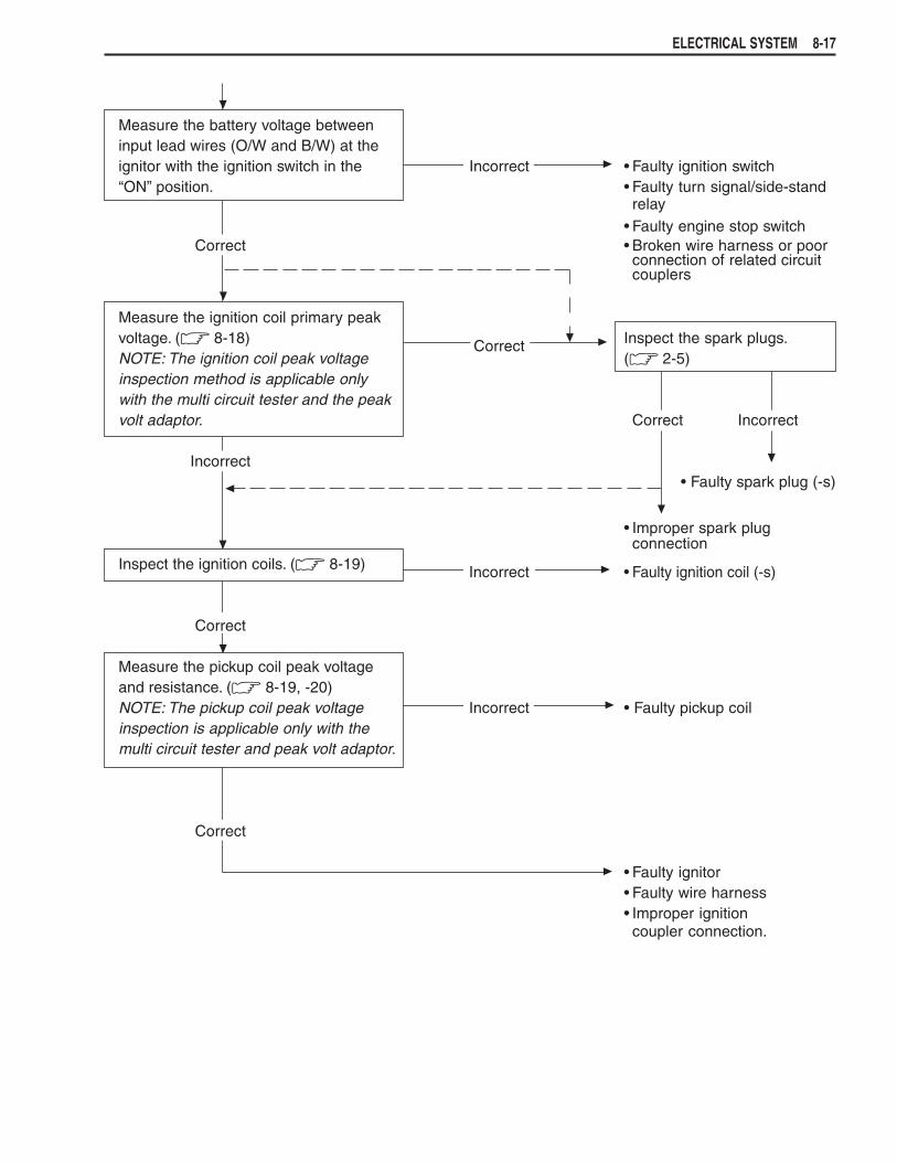
Measure the battery voltage betweeninput lead wires (O/W and B/W) at theignitor with the ignition switch in the Incorrect • Faulty ignition switch“ON” position. • Faulty turn signal/side-stand
relay• Faulty engine stop switch
Correct • Broken wire harness or poorconnection of related circuitcouplers
Measure the ignition coil primary peakvoltage. (& 8-18) Inspect the spark plugs.NOTE: The ignition coil peak voltage
Correct(& 2-5)
inspection method is applicable onlywith the multi circuit tester and the peakvolt adaptor. Correct Incorrect
Incorrect• Faulty spark plug (-s)
• Improper spark plugconnection
Inspect the ignition coils. (& 8-19) Incorrect • Faulty ignition coil (-s)
Correct
Measure the pickup coil peak voltageand resistance. (& 8-19, -20)NOTE: The pickup coil peak voltage Incorrect • Faulty pickup coilinspection is applicable only with themulti circuit tester and peak volt adaptor.
Correct
• Faulty ignitor• Faulty wire harness• Improper ignitioncoupler connection.

8-18 ELECTRICAL SYSTEM
Peak voltadaptor
Ignitor
IG coil
To enginestop switch
INSPECTIONIGNITION COIL PRIMARY PEAK VOLTAGE• Remove the fuel tank. (&5-3)• Disconnect the two spark plug caps.• Connect the new spark plugs to the each spark plug cap and
ground them on the cylinder head.
NOTE:Make sure that the each spark plug cap and spark plug are con-nected properly.
Measure the ignition coil primary peak voltage using the multicircuit tester in the following procedure.• Connect the multi circuit tester with the peak volt adaptor as
follows.No.1 ignition coil + Probe: White lead wire connector
- Probe: GroundNo.2 ignition coil + Probe: Black/Yellow lead wire connector
- Probe: Ground
NOTE:Do not disconnect the ignition coil primary lead wires.
" 09900-25008: Multi circuit tester set
!Before using the multi circuit tester and peak volt adap-tor, be sure to refer to the appropriate instruction manual.
• Shift the transmission into neutral, and then turn the ignitionswitch to the “ON” position.
• Pull the clutch lever.• Press the starter button and allow the engine to crank for a few
seconds, and then measure the ignition coil primary peak volt-age.
• Repeat the above procedure a few times and measure the high-est ignition coil primary peak voltage.
' Tester knob indication: voltage (((((()
# Ignition coil primary peak voltage: More than 200 V
)While testing, do not touch the tester probes and sparkplugs to prevent receiving an electric shock.
If the peak voltage is lower than the specified values, inspect theignition coil. (&8-19)

ELECTRICAL SYSTEM 8-19
PICKUP COIL PEAK VOLTAGE• Remove the two seats. (&7-2)• Disconnect the wire harness coupler 1 at the ignitor.
NOTE:Make sure that all of the couplers are connected properly.
Measure the pickup coil peak voltage in the following procedure.• Connect the multi circuit tester with the peak volt adaptor as
follows.
+ Probe: Blue/White lead wire- Probe: Green lead wire
" 09900-25008: Multi circuit tester set
!Before using the multi circuit tester and peak volt adap-tor, be sure to refer to the appropriate instruction manual.
IGNITION COIL RESISTANCE• Remove the fuel tank. (&5-3)• Disconnect the ignition coil lead wires and plug caps.Measure the ignition coil resistance in both the primary and sec-ondary windings. If the resistance is not within the standard range,replace the ignition coil with a new one.
" 09900-25008: Multi circuit tester set
* Tester knob indication: Resistance (Ω)
# Ignition coil resistancePrimary : 2 – 6 ΩΩΩΩΩ (Terminal – Terminal)Secondary : 15 – 30 kΩΩΩΩΩ (Plug cap – Terminal)

8-20 ELECTRICAL SYSTEM
Pickup coil
Pickup coilcoupler
Pickup coilPeakvoltadaptor
Pickup coilcoupler
G
Bl
Pickup coil
Pickup coilcoupler
Ignitorcoupler
Peakvoltadaptor
G
Bl/W
• Shift the transmission into the neutral, and then turn the igni-tion switch to the “ON” position.
• Pull the clutch lever.• Press the starter button and allow the engine to crank for a few
seconds, and then measure the pickup coil peak voltage.• Repeat the above procedure a few times and measure the high-
est peak voltage.
' Tester knob indication: Voltage (((((()
# Pickup coil peak voltage: More than 1.5 V
If the peak voltage is lower than the specified values, check thepeak voltage at the pickup coil lead wire coupler.
• Remove the secondary gear case cover.• Disconnect the pickup coil lead wire coupler and connect the
multi circuit tester with the peak volt adaptor.
+ Probe: Blue lead wire- Probe: Green lead wire
Measure the pickup coil peak voltage at the pickup coil lead wirecoupler, in the same manner as on the ignitor coupler.
' Tester knob indication: Voltage (((((()
# Pickup coil peak voltage: More than 1.5 V
If the peak voltage on the pickup coil lead wire coupler is ok buton the ignitor coupler is out of specification, the wire harnessmust be replaced. If both peak voltages are out of specification,the generator must be replaced and re-checked.
PICKUP COIL RESISTANCEMeasure the resistance between the lead wires and ground. Ifthe resistance is not specified value, the pickup coil must be re-placed.
" 09900-25008: Multi circuit tester set
* Tester knob indication: Resistance (ΩΩΩΩΩ)
# Pickup coil resistance : 160 – 300 ΩΩΩΩΩ (Green – Blue): ∞∞∞∞∞ ΩΩΩΩΩ (Green – Ground)

ELECTRICAL SYSTEM 8-21
SPEEDOMETER
REMOVAL• Remove the screws.
• Disconnect the cover and coupler.
!When disconnecting and connecting the combinationmeter coupler, make sure to turn OFF the ignition switch,or electronic parts may get damaged.
• Remove the speedometer.

8-22 ELECTRICAL SYSTEM
PARTS NAMES
1 High beam indicator light2 Engine coolant temperature
indicator light3 Turn signal indicator light4 Oil pressure indicator light5 Neutral indicator light6 Fuel level meter7 Speedometer/tripmeter/clock8 SELECT button9 ADJUST button
OPERATING PROCEDUREINITIAL DISPLAYWhen the ignition switch is set to ON, all LCD light up for threeseconds.
NOTE:If the power supply is cut (e, g, when the battery is replaced):
* The odometer, tripmeter and clock are displayed after the ini-tial display appears.
* Since the clock resets to “1:00”, it will need to be readjusted.
CHANGE THE DISPLAY MODEWith each press of the SELECT button, the display changes be-tween odometer, tripmeter A, tripmeter B and clock as shown.
)To avoid riding with only one hand, do not operate thebuttons while riding.
ODOMETER• Displays the total distance travelled.
TRIPMETER• Displays the distance travelled since the tripmeter was last re-
set.
NOTE:The tripmeters A and B can be used independently.• Hold down the ADJUST button for two seconds to reset the
tripmeter.
Odometer ClockTripmeter A Tripmeter B

ELECTRICAL SYSTEM 8-23
0.5 second 3 seconds 3 seconds
3.5 seconds 3 seconds
CLOCK• Displays the time (hours and minutes) on a 12-hour clock.• Setting the time.Hold down the ADJUST button for two seconds while pressingthe SELECT button and then flashing the hour display.
The setting that isflashing can bechanged.
FUEL LEVEL INDICATOR• Displays the amount of fuel remaining in the fuel tank.
SPEEDOMETER• The speedometer pointer operates onetime as shown below to
reset speedometer pointer, when connecting the battery orspeedometer coupler.
1. When the speedometer pointer is normal position.
2. When the speedometer pointer is top position.
3. When the speedometer pointer is bottom position.
NOTE:The speedometer pointer can indicates case 2 or case 3 if the battery terminal or speedometer lead wirecoupler is disconnected while riding.
hour min. No FlashingSelect the correcttime.
hour

8-24 ELECTRICAL SYSTEM
To oil pressureswitch
INSPECTIONENGINE COOLANT TEMPERATURE INDICATOR LIGHTEngine coolant temperature sensor inspection: &6-8• Remove the fuel tank. (&5-3)• Disconnect the engine coolant temperature sensor coupler.• Connect the jumper wire to the wire harness coupler.Check that the LED light immediately after turning the ignitionswitch on. If the LED fail in operation, replace the speedometerunit with a new one.
Main wiringharness
To engine coolanttemp. sensor
OIL PRESSURE INDICATOR LIGHT
NOTE:Before inspecting the oil pressure switch, check if the engine oillevel is enough. (&2-8)
• Disconnect the oil pressure switch lead wire from the oil pres-sure switch.
• Turn the ignition switch “ON” position.Check if the oil pressure indicator will light, when grounding thelead wire.

ELECTRICAL SYSTEM 8-25
Main wiringharness
To fuel levelgauge
Resistor
FUEL LEVEL METER• Remove the fuel tank. (&5-3)• Connect the speedometer.• Connect each resistor between the Yellow/Black and Black/
White lead wire at the wire harness.• Turn the ignition switch “ON” position and wait for approx, 13
seconds.Check the display of fuel meter as shown below. If any abnormal-ity is found, replace the speedometer with a new one.
ResistanceLess than
22 – 28 Ω 33 – 49 Ω 54 – 69 Ω 74 – 83 ΩMore than
17 Ω 94 ΩFuel level
meter
Flicker
8-26 ELECTRICAL SYSTEM
(Top)
(Bottom)
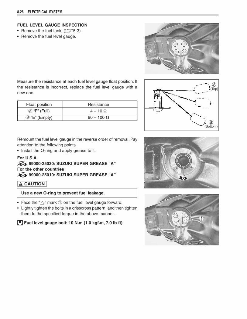
FUEL LEVEL GAUGE INSPECTION• Remove the fuel tank. (&5-3)• Remove the fuel level gauge.
Measure the resistance at each fuel level gauge float position. Ifthe resistance is incorrect, replace the fuel level gauge with anew one.
Float position Resistance
A “F” (Full) 4 – 10 ΩB “E” (Empty) 90 – 100 Ω
Remount the fuel level gauge in the reverse order of removal. Payattention to the following points.• Install the O-ring and apply grease to it.
For U.S.A.+ 99000-25030: SUZUKI SUPER GREASE “A”For the other countries+ 99000-25010: SUZUKI SUPER GREASE “A”
!
Use a new O-ring to prevent fuel leakage.
• Face the “ ” mark 1 on the fuel level gauge forward.• Lightly tighten the bolts in a crisscross pattern, and then tighten
them to the specified torque in the above manner.
, Fuel level gauge bolt: 10 N.m (1.0 kgf.m, 7.0 lb-ft)

ELECTRICAL SYSTEM 8-27
V 10 kΩ 12 V
B/W
P O/R
Speed sensor
SPEED SENSOR INSPECTIONIf the speedometer, odometer or tripmeter does not function prop-erly. Inspect the speed sensor and connection of couplers. If thespeed sensor and connection is all right, replace the unit with anew one.• Remove the front wheel. (&7-4)• Remove the head light.• Disconnect the speed sensor lead wire coupler.• Remove the speed sensor.• Connect 12V battery (between O/R and B/W), 10 kΩ resistor
(between O/R and P) and the multi circuit tester (+ probe oftester to O/R and - to P) as shown right illustration.
O/R : Orange with Red tracerB/W: Black with White tracerP : Pink
" 09900-25008: Multi circuit tester set
' Tester knob indication: Voltage (((((()
Under above condition, by rotating the drive lugs of speed sensorslowly, the tester reading voltage relatively changes (0V → 12Vor 12V → 0V). If the tester reading voltage does not change, re-place the speed sensor with a new one.
NOTE:The highest tester reading voltage (12V) while testing is same asbattery voltage.

8-28 ELECTRICAL SYSTEM
LAMPSHEADLIGHT, BRAKE LIGHT/TAILLIGHT AND TURN SIGNAL LIGHT
!If you touch the bulb with your bare hands, clean the bulb with a cloth moistened withalcohol or soapy water to prevent premature bulb failure.
HEADLIGHT BEAM ADJUSTMENT• Adjust the headlight beam, both vertical and horizontal.
BRAKE LIGHT/TAILLIGHT12 V 21/5 W
HEADLIGHT12 V 60/55 W ............... For E-03, 24, 28, 3312 V 60/55 W + 4 W ..... For E-02,19
For E-02, 19
TURN SIGNAL LIGHTFront12 V 21/5 W .....For E-03, 28, 3312 V 21 W.........For E-02, 19, 24Rear12 V 21 W

ELECTRICAL SYSTEM 8-29
RELAYSTURN SIGNAL/SIDE-STAND RELAYThe turn signal/side-stand relay is composed of the turn signalrelay, side-stand relay and diode.
INSPECTIONBefore removing the turn signal/side-stand relay, check the op-eration of the turn signal light.If the turn signal light does not illuminate, inspect the bulb, turnsignal switch and circuit connection.If the bulb, turn signal switch and circuit connection are OK, theturn signal relay may be faulty; therefore, replace the turn signal/side-stand relay with a new one.
NOTE:* Make sure that the battery is fully charged.* Refer to the page 8-15 for the side-stand relay and diode in-
spection.
SWITCHESIGNITION SWITCH REMOVAL• Remove the fuel tank. (&5-3)• Remove the frame head covers. (&6-4)• Disconnect the coupler.• Remove the ignition switch mounting bolts using the special
tool.
" 09930-11920: Torx bit JT40H09930-11940: Bit holder
!When reusing the ignition switch bolt, clean thread andapply the THREAD LOCK SUPER “1303”
-99000-32030: THREAD LOCK SUPER “1303”
STARTER RELAY&8-13

8-30 ELECTRICAL SYSTEM
Inspect each switch for continuity with a tester. If anyabnormality is found, replace the respective switchassemblies with new ones.
IGNITION SWITCH(For E-24)
R O O/Y B/W
ONOFF
LOCK
ColorPosition
(For Others)
R O O/Y B/W Gr Br
ONOFF
LOCKP
ColorPosition
LIGHTING SWITCH(Except for E-03, 24, 28 and 33)
O/Bl Gr O/R Y/W
OFF ( )
S ( )
ON ( )
ColorPosition
DIMMER SWITCH
W Y Y/W
HI ( )
LO ( )
ColorPosition
TURN SIGNAL SWITCH
Lg Lbl B
LPUSH
R
ColorPosition
PASSING LIGHT SWITCH(Except for E-03, 28 and 33)
O/R Y
PUSH
ColorPosition
ENGINE STOP SWITCH
O/B O/W
OFF ( )
RUN ( )
ColorPosition
STARTER BUTTON
O/W Y/G
PUSH
ColorPosition
HORN BUTTON
B/Bl B/W
PUSH
ColorPosition
FRONT BRAKE SWITCH
B/R B
OFFON
ColorPosition
REAR BRAKE SWITCH
CLUTCH LEVER POSITION SWITCH
B/Y B/Y
OFFON
ColorPosition
OIL PRESSURE SWITCHColor
PositionG/Y Ground
ON (engineis stopped)
OFF (engineis running)
NOTE:Before inspecting the oil pressure switch, check if theengine oil level is enough. (&2-8)
WIRE COLORB : Black Lbl : Light blue R : RedBr : Brown Lg : Light green Y : YellowGr : Gray O : Orange W : WhiteB/Bl : Black with Blue tracerB/W : Black with White tracerB/Y : Black with Yellow tracerB/R : Black with Red tracerG/Y : Green with Yellow tracerO/B : Orange with Black tracerO/Bl : Orange with Blue tracerO/R : Orange with Red tracerO/W : Orange with White tracerO/Y : Orange with Yellow tracerY/G : Yellow with Green tracerY/W : Yellow with White tracer
Terminal Terminal
OFFON
ColorPosition

ELECTRICAL SYSTEM 8-31
BATTERYSPECIFICATIONS
Type designation FTX12-BSCapacity 12V, 36 kC (10 Ah)/10HR
INITIAL CHARGINGFILLING ELECTROLYTE• Remove the aluminum tape 1 which seals the battery filler
holes 2.
• Remove the caps 3 from the electrolyte container.
NOTE:* Do not remove or pierce the sealed areas 4 of the electrolyte
container.* After completely filling the battery with electrolyte, use the caps3 from the electrolyte container to seal the battery filler holes.
• Insert the nozzles of the electrolyte container 5 into the elec-trolyte filler holes of the battery. Hold the electrolyte containerfirmly so that it does not fall. Do not allow any of the electrolyteto spill.
• Make sure the air bubbles rise to the top of each electrolytecontainer and leave the electrolyte container in this position formore than 20 minutes.
8-32 ELECTRICAL SYSTEM
CORRECT INCORRECT
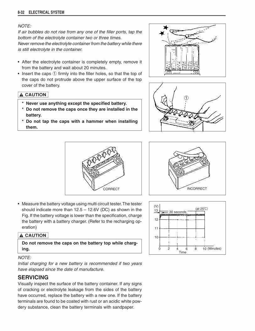
NOTE:If air bubbles do not rise from any one of the filler ports, tap thebottom of the electrolyte container two or three times.Never remove the electrolyte container from the battery while thereis still electrolyte in the container.
• After the electrolyte container is completely empty, remove itfrom the battery and wait about 20 minutes.
• Insert the caps 1 firmly into the filler holes, so that the top ofthe caps do not protrude above the upper surface of the topcover of the battery.
!* Never use anything except the specified battery.* Do not remove the caps once they are installed in the
battery.* Do not tap the caps with a hammer when installing
them.
• Measure the battery voltage using multi circuit tester. The testershould indicate more than 12.5 – 12.6V (DC) as shown in theFig. If the battery voltage is lower than the specification, chargethe battery with a battery charger. (Refer to the recharging op-eration)
!Do not remove the caps on the battery top while charg-ing.
NOTE:Initial charging for a new battery is recommended if two yearshave elapsed since the date of manufacture.
SERVICINGVisually inspect the surface of the battery container. If any signsof cracking or electrolyte leakage from the sides of the batteryhave occurred, replace the battery with a new one. If the batteryterminals are found to be coated with rust or an acidic white pow-dery substance, clean the battery terminals with sandpaper.

ELECTRICAL SYSTEM 8-33
RECHARGING OPERATION• Measure the battery voltage using the multi circuit tester. If the
voltage reading is less than the 12.0V (DC), recharge the bat-tery with a battery charger.
!* When recharging the battery, remove the battery from
the motorcycle.* Do not remove the caps on the battery top while re-
charging.
Recharging time: 1.2A for 5 to 10 hours or 5A for one hour
!Be careful not to permit the charging current to exceed5A at any time.
• After recharging, wait at least 30 minutes and then measurethe battery voltage using the multi circuit tester. If the batteryvoltage is less than 12.5V, recharge the battery again. If batteryvoltage is still less than 12.5V after recharging, replace thebattery with a new one. When a battery is left unused for a longtime, its voltage needs to be regularly measured. When themotorcycle is not used for more than one month (especiallyduring the winter season), measure the battery voltage at leastonce a month.