Electrical Submersible Pumping (ESP) Systems · supply pump monitoring data. Cable Pump Intake Seal...
51
Electrical Submersible Pumping (ESP) Systems By Matthew Amao Sunday, March 09, 2014 Artificial Lift Methods and Surface Operations PGE 482 1
Transcript of Electrical Submersible Pumping (ESP) Systems · supply pump monitoring data. Cable Pump Intake Seal...
Electrical Submersible Pumping (ESP) Systems
By
Matthew Amao
Sunday, March 09, 2014 Artificial Lift Methods and Surface Operations PGE 482 1
Lecture Outline
• Components and Operating Mechanism
– Downhole Equipment
– Surface Equipment
– Gas Separators
• Installation Design
• Class Examples
• Operational Notes
• Summary
Sunday, March 09, 2014 Artificial Lift Methods and Surface Operations PGE 482 2

3
Overview of ESP
ESP Service Providers
• Schlumberger-REDA
• Centrilift – Baker Hughes
• Weatherford
• Wood Group ESP
• ALNAS (Russia)
Sunday, March 09, 2014 Artificial Lift Methods and Surface Operations PGE 482 4
5
ESP SYSTEM
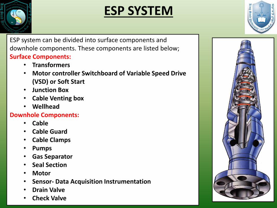
ESP system can be divided into surface components and downhole components. These components are listed below; Surface Components:
• Transformers • Motor controller Switchboard of Variable Speed Drive
(VSD) or Soft Start • Junction Box • Cable Venting box • Wellhead
Downhole Components: • Cable • Cable Guard • Cable Clamps • Pumps • Gas Separator • Seal Section • Motor • Sensor- Data Acquisition Instrumentation • Drain Valve • Check Valve

Downhole Centrifugal Pump
• Centrifugal pump is so named
because the head added to fluid is due
largely to centrifugal effects
• Characterized by:
– Small diameter
– Large quantity of stages
– High design loads

Pump Stage
• Fluid enters impeller
through ‘eye’ near shaft
and exits impeller on outer
diameter (OD)
• Diffuser (in blue) redirects
fluid into next impeller

Pump Impeller

Impeller in Diffuser = A Pump ‘Stage’
Mixed Flow Stage
Radial Flow Stage

• Cut-away view of two
impellers and diffusers
• By stacking impellers and
diffusers (multi-staging),
desired lift (TDH-Total
Dynamic Head) is achieved
Pump Stage

• Used in applications
where free gas causes
interference with pump
performance
• Units separate some of
free gas from fluid
stream entering pump
to improve pump’s
performance
Homogenizer Separators
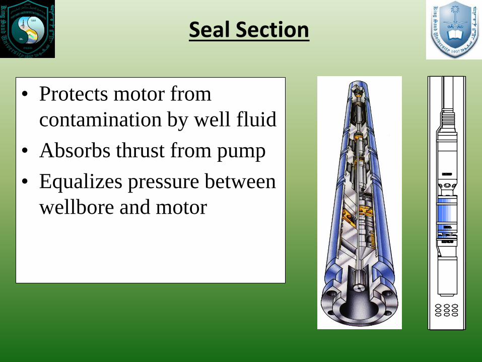
• Protects motor from
contamination by well fluid
• Absorbs thrust from pump
• Equalizes pressure between
wellbore and motor
Seal Section
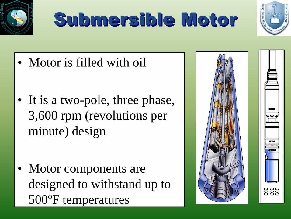
Submersible Motor
• Motor is filled with oil
• It is a two-pole, three phase,
3,600 rpm (revolutions per
minute) design
• Motor components are
designed to withstand up to
500oF temperatures
Sunday, March 09, 2014 Artificial Lift Methods and Surface Operations PGE 482 14
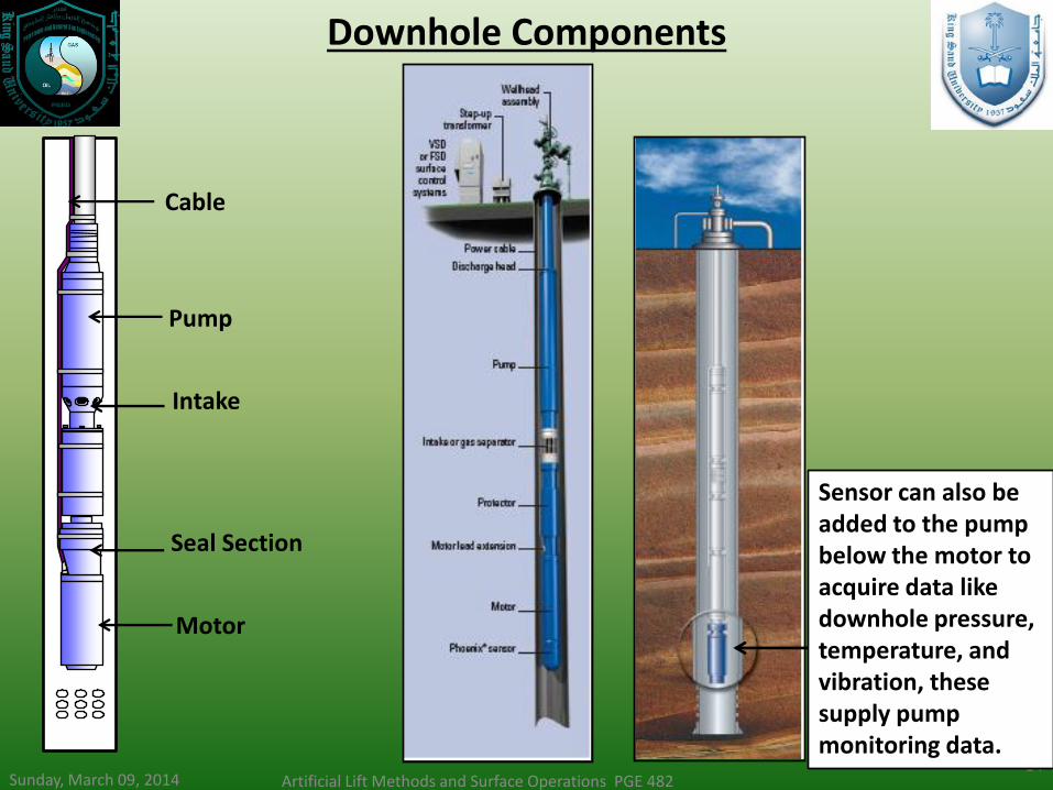
Downhole Components
Sensor can also be added to the pump below the motor to acquire data like downhole pressure, temperature, and vibration, these supply pump monitoring data.
Cable
Pump
Intake
Seal Section
Motor
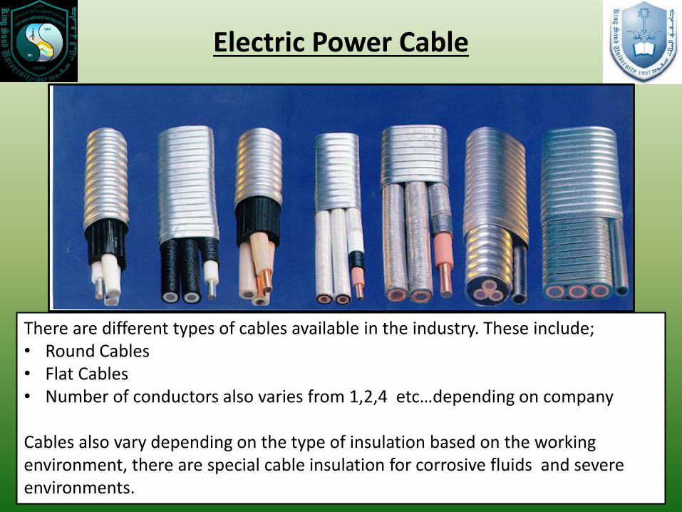
Electric Power Cable
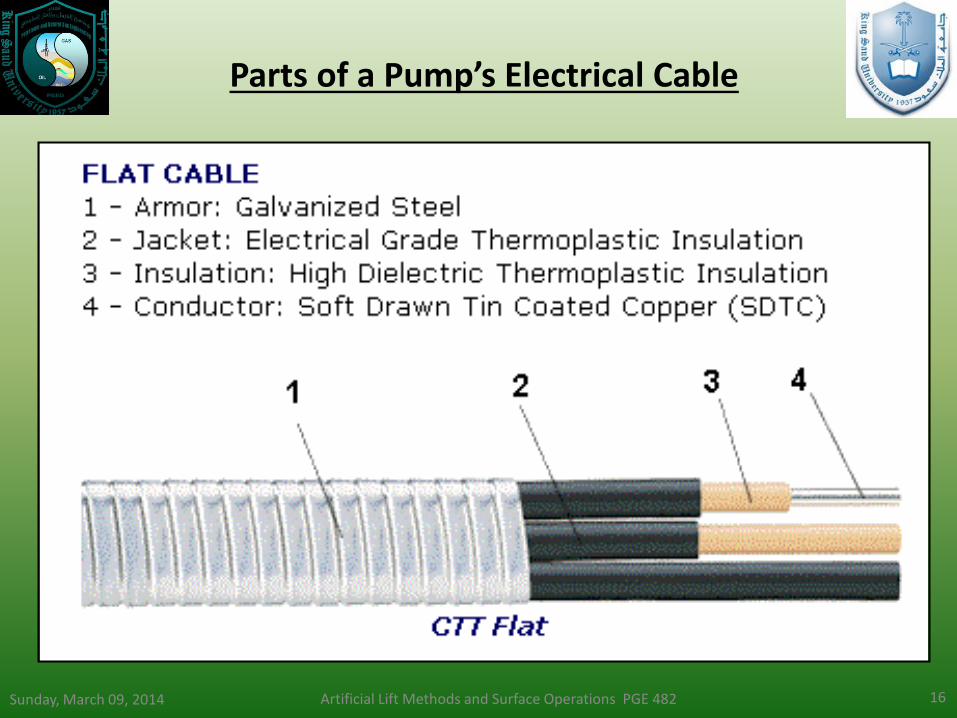
There are different types of cables available in the industry. These include; • Round Cables • Flat Cables • Number of conductors also varies from 1,2,4 etc…depending on company Cables also vary depending on the type of insulation based on the working environment, there are special cable insulation for corrosive fluids and severe environments.
Sunday, March 09, 2014 Artificial Lift Methods and Surface Operations PGE 482 16
Parts of a Pump’s Electrical Cable
17
Surface Equipment: Transformer
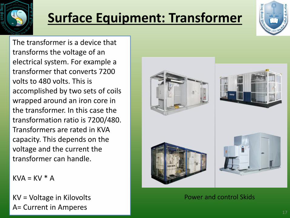
Power and control Skids
The transformer is a device that transforms the voltage of an electrical system. For example a transformer that converts 7200 volts to 480 volts. This is accomplished by two sets of coils wrapped around an iron core in the transformer. In this case the transformation ratio is 7200/480. Transformers are rated in KVA capacity. This depends on the voltage and the current the transformer can handle. KVA = KV * A KV = Voltage in Kilovolts A= Current in Amperes
Sunday, March 09, 2014 Artificial Lift Methods and Surface Operations PGE 482 18
Surface Equipment: Motor Controllers
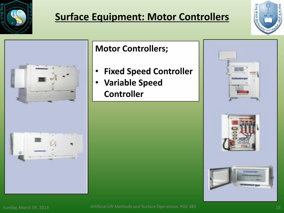
Motor Controllers; • Fixed Speed Controller • Variable Speed
Controller

Sunday, March 09, 2014 Artificial Lift Methods and Surface Operations PGE 482 19
EQUIPMENT SIZING AND
DESIGN
Sunday, March 09, 2014 Artificial Lift Methods and Surface Operations PGE 482 20
ESP
Des
ign
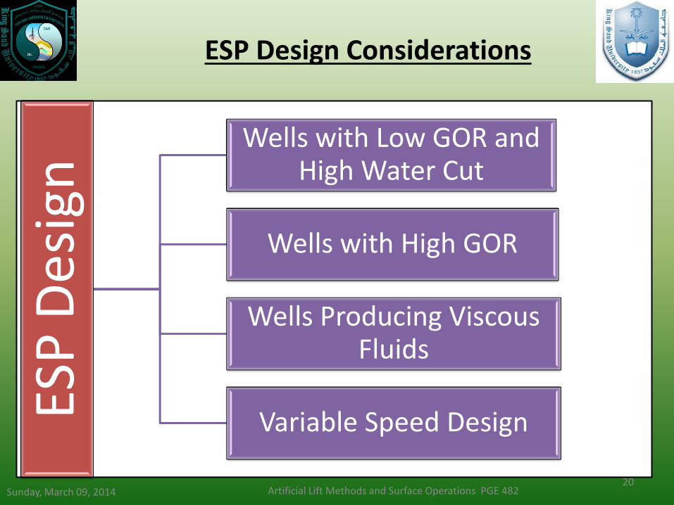
Wells with Low GOR and High Water Cut
Wells with High GOR
Wells Producing Viscous Fluids
Variable Speed Design
ESP Design Considerations

Sunday, March 09, 2014 Artificial Lift Methods and Surface Operations PGE 482 21
Design Guidelines Steps Based Design
STEP Design Task Description
1 Basic Data Collect and analyze all well data to be used
2 Well Production Capacity Determine the production capacity and depth
3 Fluid Volume Calculations Calculate all fluid volumes at pump intake pressure
4 Total Dynamic Head (TDH) Determine the pump’s discharge requirements
5 Pump Type Select pump that has highest efficiency based on desired flow rate
6 Optimum Size of Components Select optimal size of pump, motor, seal section and check the limitations if any
7 Electric Cable Select correct type and size of cable based on well
8 Accessory and Optional Equipment
Select motor controller, transformer, tubing head and other optional equipment
9 Variable Speed Pumping System
For additional operational flexibility, select the variable speed submersible pumping system
Sunday, March 09, 2014 Artificial Lift Methods and Surface Operations PGE 482 22
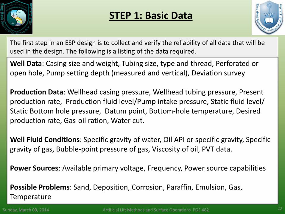
STEP 1: Basic Data
The first step in an ESP design is to collect and verify the reliability of all data that will be used in the design. The following is a listing of the data required.
Well Data: Casing size and weight, Tubing size, type and thread, Perforated or open hole, Pump setting depth (measured and vertical), Deviation survey Production Data: Wellhead casing pressure, Wellhead tubing pressure, Present production rate, Production fluid level/Pump intake pressure, Static fluid level/ Static Bottom hole pressure, Datum point, Bottom-hole temperature, Desired production rate, Gas-oil ration, Water cut. Well Fluid Conditions: Specific gravity of water, Oil API or specific gravity, Specific gravity of gas, Bubble-point pressure of gas, Viscosity of oil, PVT data. Power Sources: Available primary voltage, Frequency, Power source capabilities Possible Problems: Sand, Deposition, Corrosion, Paraffin, Emulsion, Gas, Temperature

Sunday, March 09, 2014 Artificial Lift Methods and Surface Operations PGE 482 23
STEP 2: Well Production Capacity
The Inflow Performance Relationship (IPR) or the Productivity Index (PI) of the well depending on the pressure regime should be integrated with the Vertical Lift Performance (VLP) Curve to determine the productive capacity of the well which would be used in the ESP design.
Sunday, March 09, 2014 Artificial Lift Methods and Surface Operations PGE 482 24
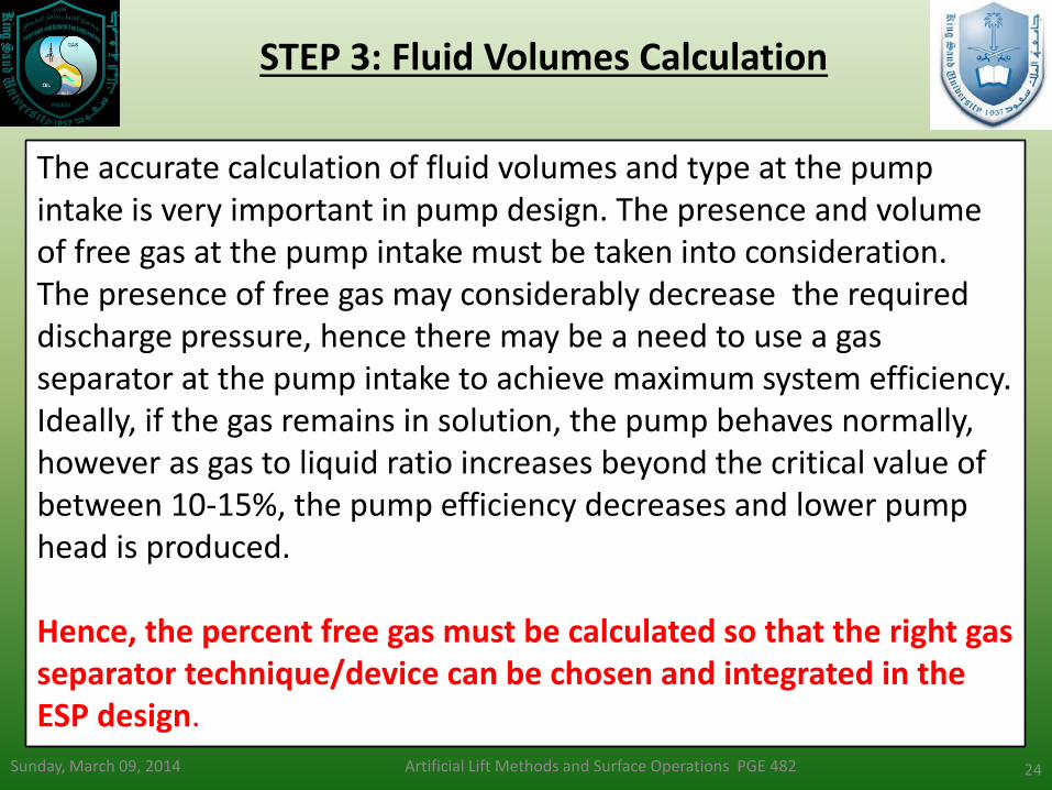
STEP 3: Fluid Volumes Calculation
The accurate calculation of fluid volumes and type at the pump intake is very important in pump design. The presence and volume of free gas at the pump intake must be taken into consideration. The presence of free gas may considerably decrease the required discharge pressure, hence there may be a need to use a gas separator at the pump intake to achieve maximum system efficiency. Ideally, if the gas remains in solution, the pump behaves normally, however as gas to liquid ratio increases beyond the critical value of between 10-15%, the pump efficiency decreases and lower pump head is produced. Hence, the percent free gas must be calculated so that the right gas separator technique/device can be chosen and integrated in the ESP design.
Artificial Lift Methods and Surface Operations PGE 482 25
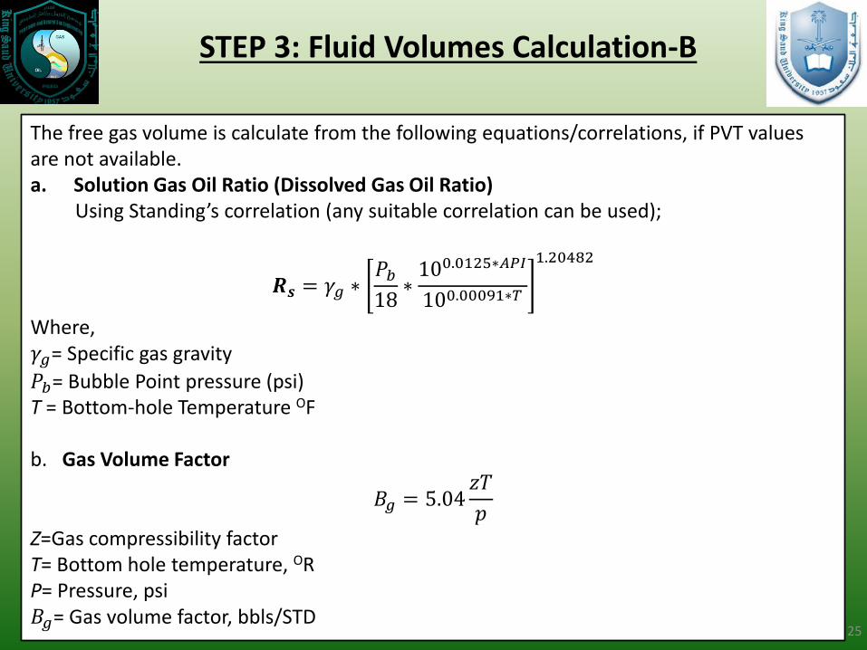
STEP 3: Fluid Volumes Calculation-B
The free gas volume is calculate from the following equations/correlations, if PVT values are not available. a. Solution Gas Oil Ratio (Dissolved Gas Oil Ratio) Using Standing’s correlation (any suitable correlation can be used);
𝑹𝒔 = 𝛾𝑔 ∗𝑃𝑏18
∗100.0125∗𝐴𝑃𝐼
100.00091∗𝑇
1.20482
Where, 𝛾𝑔= Specific gas gravity
𝑃𝑏= Bubble Point pressure (psi) T = Bottom-hole Temperature OF b. Gas Volume Factor
𝐵𝑔 = 5.04𝑧𝑇
𝑝
Z=Gas compressibility factor T= Bottom hole temperature, OR P= Pressure, psi 𝐵𝑔= Gas volume factor, bbls/STD

Sunday, March 09, 2014 Artificial Lift Methods and Surface Operations PGE 482 26
STEP 3: Fluid Volumes Calculation-C
c. Oil Formation Volume Factor, Bo
𝐵𝑜 = 0.972 + 0.000147 ∗ 𝑅𝑠 ∗𝛾𝑔
𝛾𝑜
0.5
+ 1.25 ∗ 𝑇
1.175
Where, 𝐵𝑜= Oil formation Volume Factor 𝑅𝑠= Solution Gas Oil Ration (SCF/STB) 𝛾𝑔= Gas Specific gravity (Relative to Air)
𝛾𝑜= Oil Specific Gravity (Relative to water)
d. Total Volume of Fluids
𝑇𝑜𝑡𝑎𝑙 𝐺𝑎𝑠 =𝑃𝑟𝑜𝑑𝑢𝑐𝑖𝑛𝑔 𝐺𝑂𝑅 ∗ 𝐵𝑂𝑃𝐷
1000= 𝑀𝐶𝐹
𝑆𝑜𝑙𝑢𝑡𝑖𝑜𝑛 𝐺𝑎𝑠 =𝑅𝑠 ∗ 𝐵𝑂𝑃𝐷
1000= 𝑀𝐶𝐹
𝐹𝑟𝑒𝑒𝑔𝑎𝑠 = 𝑇𝑜𝑡𝑎𝑙 𝐺𝑎𝑠 − 𝑆𝑜𝑙𝑢𝑡𝑖𝑜𝑛 𝑔𝑎𝑠
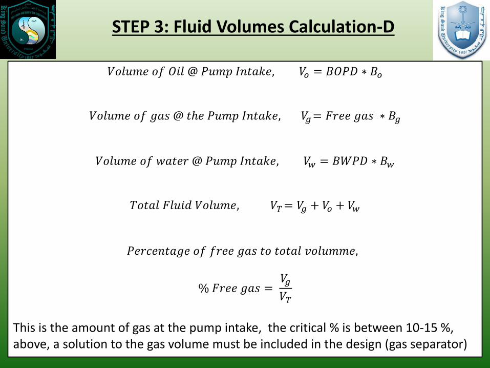
STEP 3: Fluid Volumes Calculation-D
𝑉𝑜𝑙𝑢𝑚𝑒 𝑜𝑓 𝑂𝑖𝑙 @ 𝑃𝑢𝑚𝑝 𝐼𝑛𝑡𝑎𝑘𝑒, 𝑉𝑜 = 𝐵𝑂𝑃𝐷 ∗ 𝐵𝑜
𝑉𝑜𝑙𝑢𝑚𝑒 𝑜𝑓 𝑔𝑎𝑠 @ 𝑡ℎ𝑒 𝑃𝑢𝑚𝑝 𝐼𝑛𝑡𝑎𝑘𝑒, 𝑉𝑔= 𝐹𝑟𝑒𝑒 𝑔𝑎𝑠 ∗ 𝐵𝑔
𝑉𝑜𝑙𝑢𝑚𝑒 𝑜𝑓 𝑤𝑎𝑡𝑒𝑟 @ 𝑃𝑢𝑚𝑝 𝐼𝑛𝑡𝑎𝑘𝑒, 𝑉𝑤 = 𝐵𝑊𝑃𝐷 ∗ 𝐵𝑤
𝑇𝑜𝑡𝑎𝑙 𝐹𝑙𝑢𝑖𝑑 𝑉𝑜𝑙𝑢𝑚𝑒, 𝑉𝑇= 𝑉𝑔 + 𝑉𝑜 + 𝑉𝑤
𝑃𝑒𝑟𝑐𝑒𝑛𝑡𝑎𝑔𝑒 𝑜𝑓 𝑓𝑟𝑒𝑒 𝑔𝑎𝑠 𝑡𝑜 𝑡𝑜𝑡𝑎𝑙 𝑣𝑜𝑙𝑢𝑚𝑚𝑒,
% 𝐹𝑟𝑒𝑒 𝑔𝑎𝑠 = 𝑉𝑔
𝑉𝑇
This is the amount of gas at the pump intake, the critical % is between 10-15 %, above, a solution to the gas volume must be included in the design (gas separator)
Sunday, March 09, 2014 Artificial Lift Methods and Surface Operations PGE 482 28
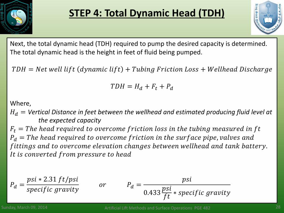
STEP 4: Total Dynamic Head (TDH)
Next, the total dynamic head (TDH) required to pump the desired capacity is determined. The total dynamic head is the height in feet of fluid being pumped. 𝑇𝐷𝐻 = 𝑁𝑒𝑡 𝑤𝑒𝑙𝑙 𝑙𝑖𝑓𝑡 𝑑𝑦𝑛𝑎𝑚𝑖𝑐 𝑙𝑖𝑓𝑡 + 𝑇𝑢𝑏𝑖𝑛𝑔 𝐹𝑟𝑖𝑐𝑡𝑖𝑜𝑛 𝐿𝑜𝑠𝑠 +𝑊𝑒𝑙𝑙ℎ𝑒𝑎𝑑 𝐷𝑖𝑠𝑐ℎ𝑎𝑟𝑔𝑒
𝑇𝐷𝐻 = 𝐻𝑑 + 𝐹𝑡 + 𝑃𝑑
Where, 𝐻𝑑 = Vertical Distance in feet between the wellhead and estimated producing fluid level at
the expected capacity 𝐹𝑡 = 𝑇ℎ𝑒 ℎ𝑒𝑎𝑑 𝑟𝑒𝑞𝑢𝑖𝑟𝑒𝑑 𝑡𝑜 𝑜𝑣𝑒𝑟𝑐𝑜𝑚𝑒 𝑓𝑟𝑖𝑐𝑡𝑖𝑜𝑛 𝑙𝑜𝑠𝑠 𝑖𝑛 𝑡ℎ𝑒 𝑡𝑢𝑏𝑖𝑛𝑔 𝑚𝑒𝑎𝑠𝑢𝑟𝑒𝑑 𝑖𝑛 𝑓𝑡 𝑃𝑑 = 𝑇ℎ𝑒 ℎ𝑒𝑎𝑑 𝑟𝑒𝑞𝑢𝑖𝑟𝑒𝑑 𝑡𝑜 𝑜𝑣𝑒𝑟𝑐𝑜𝑚𝑒 𝑓𝑟𝑖𝑐𝑡𝑖𝑜𝑛 𝑖𝑛 𝑡ℎ𝑒 𝑠𝑢𝑟𝑓𝑎𝑐𝑒 𝑝𝑖𝑝𝑒, 𝑣𝑎𝑙𝑣𝑒𝑠 𝑎𝑛𝑑 𝑓𝑖𝑡𝑡𝑖𝑛𝑔𝑠 𝑎𝑛𝑑 𝑡𝑜 𝑜𝑣𝑒𝑟𝑐𝑜𝑚𝑒 𝑒𝑙𝑒𝑣𝑎𝑡𝑖𝑜𝑛 𝑐ℎ𝑎𝑛𝑔𝑒𝑠 𝑏𝑒𝑡𝑤𝑒𝑒𝑛 𝑤𝑒𝑙𝑙ℎ𝑒𝑎𝑑 𝑎𝑛𝑑 𝑡𝑎𝑛𝑘 𝑏𝑎𝑡𝑡𝑒𝑟𝑦. 𝐼𝑡 𝑖𝑠 𝑐𝑜𝑛𝑣𝑒𝑟𝑡𝑒𝑑 𝑓𝑟𝑜𝑚 𝑝𝑟𝑒𝑠𝑠𝑢𝑟𝑒 𝑡𝑜 ℎ𝑒𝑎𝑑
𝑃𝑑 =𝑝𝑠𝑖 ∗ 2.31 𝑓𝑡/𝑝𝑠𝑖
𝑠𝑝𝑒𝑐𝑖𝑓𝑖𝑐 𝑔𝑟𝑎𝑣𝑖𝑡𝑦 𝑜𝑟 𝑃𝑑 =
𝑝𝑠𝑖
0.433𝑝𝑠𝑖𝑓𝑡
∗ 𝑠𝑝𝑒𝑐𝑖𝑓𝑖𝑐 𝑔𝑟𝑎𝑣𝑖𝑡𝑦
=
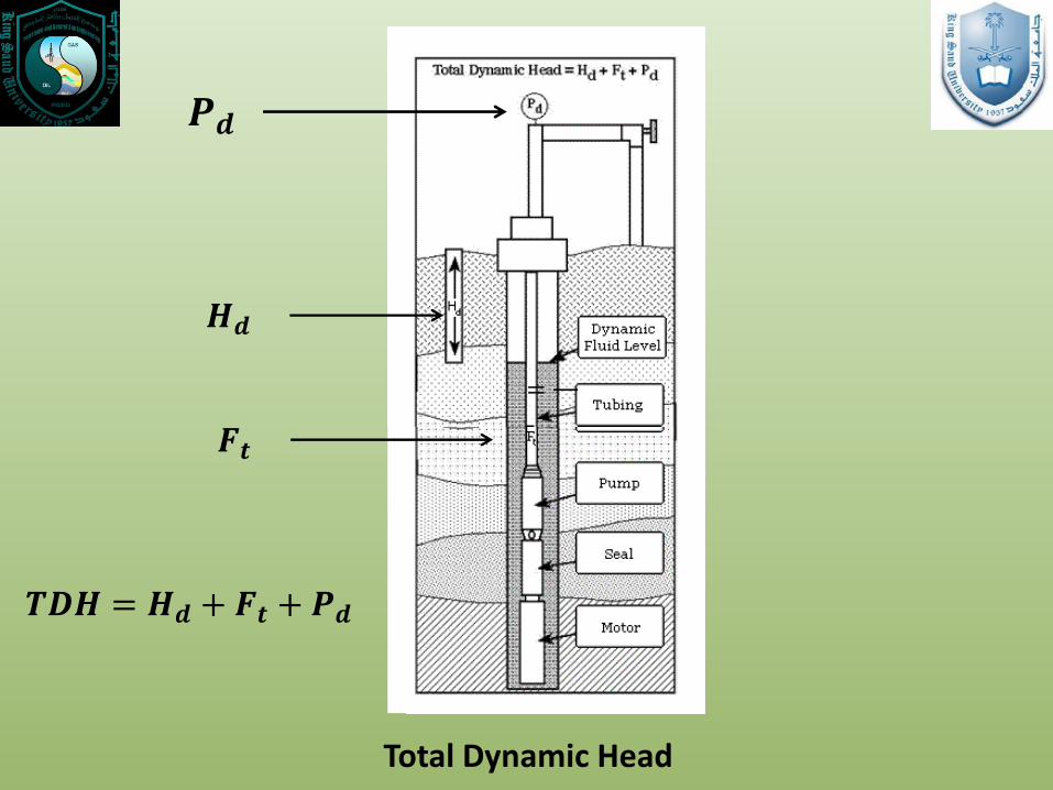
𝑭𝒕
𝑯𝒅
𝑷𝒅
𝑻𝑫𝑯 = 𝑯𝒅 + 𝑭𝒕 + 𝑷𝒅
Total Dynamic Head
Sunday, March 09, 2014 Artificial Lift Methods and Surface Operations PGE 482 30
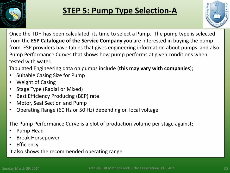
STEP 5: Pump Type Selection-A
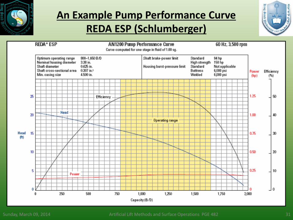
Once the TDH has been calculated, its time to select a Pump. The pump type is selected from the ESP Catalogue of the Service Company you are interested in buying the pump from. ESP providers have tables that gives engineering information about pumps and also Pump Performance Curves that shows how pump performs at given conditions when tested with water. Tabulated Engineering data on pumps include (this may vary with companies); • Suitable Casing Size for Pump • Weight of Casing • Stage Type (Radial or Mixed) • Best Efficiency Producing (BEP) rate • Motor, Seal Section and Pump • Operating Range (60 Hz or 50 Hz) depending on local voltage The Pump Performance Curve is a plot of production volume per stage against; • Pump Head • Break Horsepower • Efficiency It also shows the recommended operating range
Sunday, March 09, 2014 Artificial Lift Methods and Surface Operations PGE 482 31
An Example Pump Performance Curve REDA ESP (Schlumberger)

Typical Pump Performance Curve Centrilift (Baker Hughes)

Sunday, March 09, 2014 Artificial Lift Methods and Surface Operations PGE 482 33
STEP 5: Pump Type Selection-B
Notes on Pump Selection: • Larger diameter pumps and motor are less expensive and they
operate at higher efficiencies. • Select the highest efficient pump that will fit in the casing • If the well’s production capacity is not accurately known, choose
a pump with a steep characteristic curve. • If desired volume falls at a point where two pumps have
approximately the same efficiency, choose the pump type which requires the greater number of stages.
• If gas is present in the produced fluid, a gas separator may be required to achieve efficient operation.
• In wells with viscous fluids or emulsions, some pump corrections may be necessary to ensure more efficient operation, hence, working with a service company personnel will be expedient.

Sunday, March 09, 2014 Artificial Lift Methods and Surface Operations PGE 482 34
STEP 5: Pump Type Selection-C
Notes on Pump Selection: In most cases there will be two or three pumps that meet the volume and diameter requirements. A comparison of efficiencies, expected production changes and actual pump efficiencies are used to select the optimum pump. Other considerations are; • Availability of pump in customer inventory • Delivery Equipment
Sunday, March 09, 2014 Artificial Lift Methods and Surface Operations PGE 482 35
STEP 6: Optimum Size of Components-A
ESP components are usually designed and build in a number of different sizes, hence the components can be assembled in a variety of combinations. These combinations must be carefully determined to operate the pump at the optimal production rate, material strength and temperature limits based on the Company’s catalogue. Engineering considerations for sizing pump’s components include; • Maximum Loading Limits • Maximum Diameter of Unit • Velocity of fluid passing a motor (this affects rate of pump cooling,
a velocity of 1 ft/s is recommended, if not achievable a motor jacket may be required to increase the velocity).
• Shaft horse power (HP) limitations at various frequencies
Sunday, March 09, 2014 Artificial Lift Methods and Surface Operations PGE 482
36
STEP 6: Optimum Size of Components-B
a. Optimum Selection of Pump From the Performance Curve of the selected pump type, determine the number of stages required to produce the anticipated capacity based on the calculated dynamic head (TDH). Note that the performance curves are single stage pump characteristic curves, hence the total stages required is determined from;
𝑇𝑜𝑡𝑎𝑙 𝑆𝑡𝑎𝑔𝑒𝑠 𝑅𝑒𝑞𝑢𝑖𝑟𝑒𝑑 =𝑇𝑜𝑡𝑎𝑙 𝐷𝑦𝑛𝑎𝑚𝑖𝑐 𝐻𝑒𝑎𝑑
𝐻𝑒𝑎𝑑 𝑝𝑒𝑟 𝑠𝑡𝑎𝑔𝑒
b. Housing Pressure Limit Maximum housing pressure will occur at pump shut in, when the maximum lift per stage is available. Worst case is when the pump is pumping against a closed valve.
𝑀𝐻𝑃 = 𝑆𝐼𝐻60 ∗ 𝑆𝑡𝑎𝑔𝑒𝑠 ∗ 𝑀𝑖𝑥𝑡𝑢𝑟𝑒 𝑔𝑟𝑎𝑑𝑖𝑒𝑛𝑡 ∗ 𝐻𝑧 60 2 𝑴𝑯𝑷: Maximum Housing Pressure SIH: Shut-in head per stage @ 60Hz. Stages: Number of pump stages Hz: Operating Frequency
Sunday, March 09, 2014 Artificial Lift Methods and Surface Operations PGE 482 37
STEP 6: Optimum Size of Components-C
C. Optimum Selection of Motor The optimum motor is selected by first determining the brake horsepower required per stage by the pump. This value is also gotten from performance curve. Therefore, brake horsepower (BHP) required to drive a pump is then calculated from; 𝐵𝐻𝑃 = 𝑇𝑜𝑡𝑎𝑙 𝑆𝑡𝑎𝑔𝑒𝑠 ∗ 𝐵𝐻𝑃 𝑝𝑒𝑟 𝑠𝑡𝑎𝑔𝑒 ∗ 𝑆𝑝𝑒𝑐𝑖𝑓𝑖𝑐 𝑔𝑟𝑎𝑣𝑖𝑡𝑦
Sunday, March 09, 2014 Artificial Lift Methods and Surface Operations PGE 482 38
STEP 6: Optimum Size of Components-C
d. Optimum Selection of the Seal Section Refer to company catalogue for recommendations based on pump type and well environment. e. Optimum Selection of Gas Separator Refer to company catalogue for recommendations based on pump type and well environment. Make the necessary adjustments in horsepower requirements and housing length. Note: More power will be needed by the motor to drive an added gas separator, this must be added on when selecting the motor, if a gas separator would be needed in the pump.

Sunday, March 09, 2014 Artificial Lift Methods and Surface Operations PGE 482 39
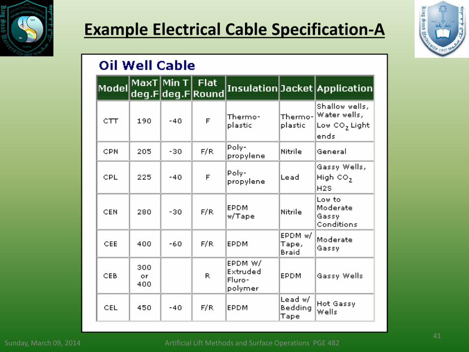
STEP 7: Electrical Cable-A
Electric cable to be used is selected based on the evaluation of the following parameters:
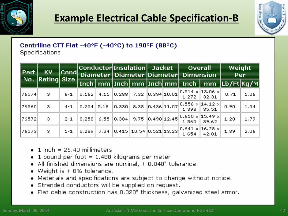
Cable Size Cable size is dependent on voltage drop, amperage and available space between casing and collars. Company catalogues have to be consulted for these values. However, its is recommended that the voltage drop should be less than 30 volts/1000 ft or less than 15% of motor nameplate voltage. This is to ensure that adequate voltage is available to operate the motor downhole. Cable Type This is based primarily on the fluid conditions, bottom-hole temperature and annular space limitations. Use flat cable for limited space installations.

Sunday, March 09, 2014 Artificial Lift Methods and Surface Operations PGE 482 40
STEP 7: Electrical Cable-B
Cable Length Total cable length should be at least 100ft more than the measured pump setting depth in order to have sufficient lengths for surface connections. Make surface connections a safe distance from the well head. Cable Venting As a safety precaution, it is necessary to vent gas from the cable prior to the motor controller to avoid explosive conditions. A cable venting box should be used for this purpose.
Sunday, March 09, 2014 Artificial Lift Methods and Surface Operations PGE 482 41
Example Electrical Cable Specification-A
Sunday, March 09, 2014 Artificial Lift Methods and Surface Operations PGE 482 42
Example Electrical Cable Specification-B
Sunday, March 09, 2014 Artificial Lift Methods and Surface Operations PGE 482 43
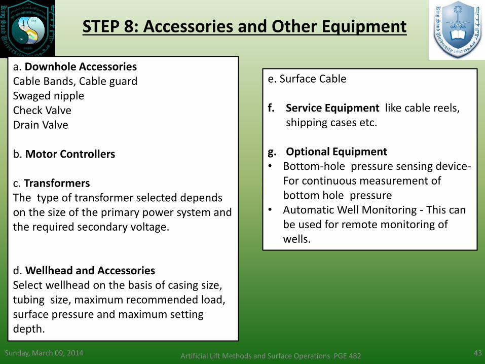
STEP 8: Accessories and Other Equipment
a. Downhole Accessories Cable Bands, Cable guard Swaged nipple Check Valve Drain Valve
b. Motor Controllers
c. Transformers The type of transformer selected depends on the size of the primary power system and the required secondary voltage. d. Wellhead and Accessories Select wellhead on the basis of casing size, tubing size, maximum recommended load, surface pressure and maximum setting depth.
e. Surface Cable f. Service Equipment like cable reels,
shipping cases etc.
g. Optional Equipment • Bottom-hole pressure sensing device-
For continuous measurement of bottom hole pressure
• Automatic Well Monitoring - This can be used for remote monitoring of wells.
Sunday, March 09, 2014 Artificial Lift Methods and Surface Operations PGE 482 44
STEP 9: Variable Speed Submersible Pumping (VSSP)
The ESP system can be modified to include an Electrospeed variable frequency controller so that it operates over a much broader range of capacity, head and efficiency. The speed of an ESP motor is proportional to its frequency of the electrical power supply. Thus by adjusting the frequency, the speed can be adjusted, this is the purpose of the variable speed system. This system offers potential for boosting production, reducing downtime, and increasing profit. Also it can be used to extend the range of a submersible pump. Also, if the production capacity of a well is not precisely known an variable speed controller can be selected for an estimated range of and adjusted for the desired production level once more data is available.

Sunday, March 09, 2014 Artificial Lift Methods and Surface Operations PGE 482 45
Design Class Examples
Question 1 Given the following data: Lift required: 6200 ft Rate: 2300 bpd Fluid SG: 1.0 Operating Frequency: 60 Hz Find: a) The number of Stages required b) The minimum motor horsepower required c) The pump efficiency
Question 2 Given the following data: Pump Depth: 7500 ft Tubing Pressure: 150 psig Pump Intake Pressure (PIP): 275 psig Rate: 3000 bpd Mixture Gradient: 0.42 psi/ft Tubing : 2 7/8 in. OD (New) Calculate: a. The Total Dynamic Head (TDH)
Question 3 Given: Casing: 7in., 26 lb/ft Rate: 2500 bpd TDH: 7427 ft Operating Frequency: 60 Hz Casing Drift Diameter: 6.151 in. Find the largest diameter pump that will fit in the casing.

46
Design Example 4
Well Data Casing: 7in. OD., 23 lbs/ft Tubing: 2 7/8 in. OD., External Upset 8 Round Thread (new) Perforations: 5300-5400 ft Pump Setting Depth: 5200 ft (measured and vertical) Production Data Wellhead Tubing Pressure: 150 psi Test Rate: 900 bpd Datum Point: 5350 ft Test Pressure: 985 psi Static bottom Hole Pressure: 1650 psi Bottom-hole Temperature: 180 OF Gas oil Ratio- Not Available Water Cut: 90% Desired Production Rate: 2000 bpd (stock Tank)
Well Fluid Conditions Water SG: 1.02 Oil API: 30O (0.876) Gas SG: Not Available Bubble Point Pressure : Not Available Viscosity of Oil: Not Available Power Sources Available Primary Voltage:7200/12470 volts Frequency: 60 Hz Power Source Capability: Stable System Possible Problems None
Question: Select a suitable Submersible Pumping System for the following well and production data.
47
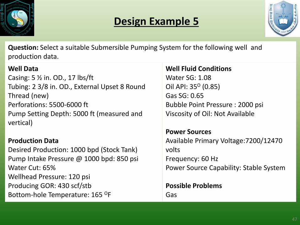
Design Example 5
Well Data Casing: 5 ½ in. OD., 17 lbs/ft Tubing: 2 3/8 in. OD., External Upset 8 Round Thread (new) Perforations: 5500-6000 ft Pump Setting Depth: 5000 ft (measured and vertical) Production Data Desired Production: 1000 bpd (Stock Tank) Pump Intake Pressure @ 1000 bpd: 850 psi Water Cut: 65% Wellhead Pressure: 120 psi Producing GOR: 430 scf/stb Bottom-hole Temperature: 165 OF
Well Fluid Conditions Water SG: 1.08 Oil API: 35O (0.85) Gas SG: 0.65 Bubble Point Pressure : 2000 psi Viscosity of Oil: Not Available Power Sources Available Primary Voltage:7200/12470 volts Frequency: 60 Hz Power Source Capability: Stable System Possible Problems Gas
Question: Select a suitable Submersible Pumping System for the following well and production data.
48
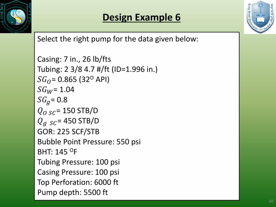
Design Example 6
Select the right pump for the data given below: Casing: 7 in., 26 lb/fts Tubing: 2 3/8 4.7 #/ft (ID=1.996 in.) 𝑆𝐺𝑂= 0.865 (32O API) 𝑆𝐺𝑊= 1.04 𝑆𝐺𝑔= 0.8
𝑄𝑂 𝑆𝐶= 150 STB/D 𝑄𝑔 𝑆𝐶= 450 STB/D
GOR: 225 SCF/STB Bubble Point Pressure: 550 psi BHT: 145 OF Tubing Pressure: 100 psi Casing Pressure: 100 psi Top Perforation: 6000 ft Pump depth: 5500 ft
Summary
• ESP system have been introduced and the operational mechanism explained in details.
• The design methodology, equations and steps were presented.
• Design examples were also shown and demonstrated in class.
Sunday, March 09, 2014 Artificial Lift Methods and Surface
Operations PGE 482 49
References
• WG Wood Group “Basic ESP Sizing Manual”, 2007
• Baker Hughes, Centrilift, “Handbook for Electrical Submersible Pumping System”, 1997.
• Schlumberger REDA Electric Submersible Pump Technology, ESP Catalogue, 2006
Sunday, March 09, 2014 Artificial Lift Methods and Surface Operations PGE 482 50

Electrical Submersible Pump Systems
By
Matthew Amao
Sunday, March 09, 2014 Artificial Lift Methods and Surface Operations PGE 482 51