
Electrical Safety Analyzer - Flukeassets.fluke.com/manuals/esa615__umeng0200.pdf · which there are...
96
FBC-0026 February 2012, Rev. 2, 2/13 © 2012, 2013 Fluke Corporation. All rights reserved. Specifications are subject to change without notice. All product names are trademarks of their respective companies. ESA615 Electrical Safety Analyzer Users Manual
Transcript of Electrical Safety Analyzer - Flukeassets.fluke.com/manuals/esa615__umeng0200.pdf · which there are...

FBC-0026 February 2012, Rev. 2, 2/13 © 2012, 2013 Fluke Corporation. All rights reserved. Specifications are subject to change without notice. All product names are trademarks of their respective companies.
ESA615 Electrical Safety Analyzer
Users Manual

Warranty and Product Support
Fluke Biomedical warrants this instrument against defects in materials and workmanship for one year from the date of original purchase OR two years if at the end of your first year you send the instrument to a Fluke Biomedical service center for calibration. You will be charged our customary fee for such calibration. During the warranty period, we will repair or at our option replace, at no charge, a product that proves to be defective, provided you return the product, shipping prepaid, to Fluke Biomedical. This warranty covers the original purchaser only and is not transferable. The warranty does not apply if the product has been damaged by accident or misuse or has been serviced or modified by anyone other than an authorized Fluke Biomedical service facility. NO OTHER WARRANTIES, SUCH AS FITNESS FOR A PARTICULAR PURPOSE, ARE EXPRESSED OR IMPLIED. FLUKE SHALL NOT BE LIABLE FOR ANY SPECIAL, INDIRECT, INCIDENTAL OR CONSEQUENTIAL DAMAGES OR LOSSES, INCLUDING LOSS OF DATA, ARISING FROM ANY CAUSE OR THEORY.
This warranty covers only serialized products and their accessory items that bear a distinct serial number tag. Recalibration of instruments is not covered under the warranty.
This warranty gives you specific legal rights and you may also have other rights that vary in different jurisdictions. Since some jurisdictions do not allow the exclusion or limitation of an implied warranty or of incidental or consequential damages, this limitation of liability may not apply to you. If any provision of this warranty is held invalid or unenforceable by a court or other decision-maker of competent jurisdiction, such holding will not affect the validity or enforceability of any other provision.
7/07

Notices
All Rights Reserved Copyright 2013, Fluke Biomedical. No part of this publication may be reproduced, transmitted, transcribed, stored in a retrieval system, or translated into any language without the written permission of Fluke Biomedical.
Copyright Release Fluke Biomedical agrees to a limited copyright release that allows you to reproduce manuals and other printed materials for use in service training programs and other technical publications. If you would like other reproductions or distributions, submit a written request to Fluke Biomedical.
Unpacking and Inspection Follow standard receiving practices upon receipt of the instrument. Check the shipping carton for damage. If damage is found, stop unpacking the instrument. Notify the carrier and ask for an agent to be present while the instrument is unpacked. There are no special unpacking instructions, but be careful not to damage the instrument when unpacking it. Inspect the instrument for physical damage such as bent or broken parts, dents, or scratches.
Technical Support For application support or answers to technical questions, either email [email protected] or call 1-800- 850-4608 or 1-440-248-9300. In Europe, email [email protected] or call +31-40-2675314.
Claims Our routine method of shipment is via common carrier, FOB origin. Upon delivery, if physical damage is found, retain all packing materials in their original condition and contact the carrier immediately to file a claim. If the instrument is delivered in good physical condition but does not operate within specifications, or if there are any other problems not caused by shipping damage, please contact Fluke Biomedical or your local sales representative.

Returns and Repairs Return Procedure
All items being returned (including all warranty-claim shipments) must be sent freight-prepaid to our factory location. When you return an instrument to Fluke Biomedical, we recommend using United Parcel Service, Federal Express, or Air Parcel Post. We also recommend that you insure your shipment for its actual replacement cost. Fluke Biomedical will not be responsible for lost shipments or instruments that are received in damaged condition due to improper packaging or handling.
Use the original carton and packaging material for shipment. If they are not available, we recommend the following guide for repackaging:
Use a double–walled carton of sufficient strength for the weight being shipped. Use heavy paper or cardboard to protect all instrument surfaces. Use nonabrasive material around all projecting parts. Use at least four inches of tightly packed, industry-approved, shock-absorbent material around the instrument.
Returns for partial refund/credit:
Every product returned for refund/credit must be accompanied by a Return Material Authorization (RMA) number, obtained from our Order Entry Group at 1-440-498-2560.
Repair and calibration:
To find the nearest service center, go to www.flukebiomedical.com/service or
In the U.S.A.: Cleveland Calibration Lab Tel: 1-800-850-4608 x2564 Email: [email protected] Everett Calibration Lab Tel: 1-888-99 FLUKE (1-888-993-5853) Email: [email protected]
In Europe, Middle East, and Africa: Eindhoven Calibration Lab Tel: +31-40-2675300 Email: [email protected] In Asia: Everett Calibration Lab Tel: +425-446-6945 Email: [email protected]
To ensure the accuracy of the Product is maintained at a high level, Fluke Biomedical recommends the product be calibrated at least once every 12 months. Calibration must be done by qualified personnel. Contact your local Fluke Biomedical representative for calibration.

Certification This instrument was thoroughly tested and inspected. It was found to meet Fluke Biomedical’s manufacturing specifications when it was shipped from the factory. Calibration measurements are traceable to the National Institute of Standards and Technology (NIST). Devices for which there are no NIST calibration standards are measured against in-house performance standards using accepted test procedures.
WARNING Unauthorized user modifications or application beyond the published specifications may result in electrical shock hazards or improper operation. Fluke Biomedical will not be responsible for any injuries sustained due to unauthorized equipment modifications.
Restrictions and Liabilities Information in this document is subject to change and does not represent a commitment by Fluke Biomedical. Changes made to the information in this document will be incorporated in new editions of the publication. No responsibility is assumed by Fluke Biomedical for the use or reliability of software or equipment that is not supplied by Fluke Biomedical, or by its affiliated dealers.
Manufacturing Location The ESA615 Electrical Safety Analyzer is manufactured at Fluke Biomedical, 6920 Seaway Blvd., Everett, WA, U.S.A.


i
Table of Contents
Title Page
Introduction .................................................................................................................... 1 Intended Use .................................................................................................................. 3 Safety Information .......................................................................................................... 3 Unpack the Product ........................................................................................................ 5 Instrument Familiarization .............................................................................................. 6 How to Hold the Product ................................................................................................ 10 How to Connect to Line Power ....................................................................................... 10 How to Connect a DUT to the Product ........................................................................... 11 How to Turn On the Product ........................................................................................... 11 How to Access the Product Functions ............................................................................ 13 How to Connect a PC to the Product .............................................................................. 14 How to Set Up the Product ............................................................................................. 16
Set the Operator Name ............................................................................................. 16 Delete an Operator Name ......................................................................................... 17 Set the Date .............................................................................................................. 18

ESA615 Users Manual
ii
Set the Time.............................................................................................................. 18 Set the Test Standard ............................................................................................... 18 Set the GFCI Limit .................................................................................................... 18 Set Polarity Switching Delay ..................................................................................... 19 Set the Date Format .................................................................................................. 19 Set the Time Format ................................................................................................. 19 Set the Language ...................................................................................................... 19 Set the Beeper .......................................................................................................... 20 Set the Display Contrast ........................................................................................... 20
How to View Instrument Information .............................................................................. 20 How to Do Electrical Safety Tests.................................................................................. 20
Set the Test Standard ............................................................................................... 21 Mains Voltage Test ................................................................................................... 21 Ground Wire (Protective Earth) Resistance Test ...................................................... 22 Insulation Resistance Test ........................................................................................ 27 Equipment Current Test ............................................................................................ 33 Leakage Current Test ............................................................................................... 33
Earth Leakage Current ......................................................................................... 34 Chassis (Enclosure) Leakage Test ...................................................................... 37 Lead-to-Ground (Patient) Leakage Test ............................................................... 39 Lead-to-Lead (Patient Auxiliary) Leakage Tests .................................................. 41
Lead Isolation (Mains on Applied Part) MAP Leakage Test ...................................... 43 Alternative Equipment Leakage Test ........................................................................ 46 Alternative Applied Part Leakage Test ...................................................................... 46 Direct Equipment Leakage Test ................................................................................ 48 Direct Applied Part Leakage Test ............................................................................. 50 Differential Leakage Current Test ............................................................................. 53
How to Use the 1-to-10 Adapter .................................................................................... 55 How to Do Point-To-Point Measurements ..................................................................... 59
Contents (continued)
iii
Measure Voltage ....................................................................................................... 59 Measure Resistance .................................................................................................. 59 Measure Current ........................................................................................................ 60
How to Simulate ECG Waveforms ................................................................................. 60 Memory .......................................................................................................................... 63 Test Sequences ............................................................................................................. 63
Factory Supplied Test Sequences ............................................................................. 63 How to Make a Test Sequence.................................................................................. 66
Make a New Test Sequence ................................................................................. 66 Make a Test Sequence from a Test Sequence in the Test Library ....................... 70
Edit a Test Sequence ................................................................................................ 70 Do a Test Sequence .................................................................................................. 71 Show Test Results ..................................................................................................... 72 Delete a Set of Test Results ...................................................................................... 73
Maintenance ................................................................................................................... 73 Fuse Test and Fuse Replacement ............................................................................. 73 How to Clean the Product .......................................................................................... 74
Replaceable Parts .......................................................................................................... 75 Accessories .................................................................................................................... 77 Specifications ................................................................................................................. 78 Detailed Specifications ................................................................................................... 79

ESA615 Users Manual
iv

v
List of Tables
Table Title Page
1. Symbols ................................................................................................................................. 2 2. Top-Panel Controls and Connections .................................................................................... 7 3. Side and Top-Panel Connections .......................................................................................... 9 4. Schematic Abbreviations ....................................................................................................... 25 5. Test Names Based on Selected Standard ............................................................................. 33 6. Factory Supplied Test Sequences ......................................................................................... 64 7. Test Settings for Test Sequences ......................................................................................... 68 8. Replaceable Parts ................................................................................................................. 75 9. Accessories ........................................................................................................................... 77

ESA615 Users Manual
vi

vii
List of Figures
Figure Title Page
1. Front-Panel Controls and Connections ................................................................................. 6 2. Side and Top-Panel Connections .......................................................................................... 8 3. Product Handle ...................................................................................................................... 10 4. Product Ready for Operation ................................................................................................. 11 5. DUT Connections to the Product ........................................................................................... 12 6. Leakage Current Menu .......................................................................................................... 14 7. Product to PC Connection ..................................................................................................... 15 8. Setup Menu ........................................................................................................................... 16 9. Operator List Screen ............................................................................................................. 16 10. Mains Voltage Test Menu ...................................................................................................... 21 11. DUT Ground Resistance Measurement................................................................................. 23 12. Ground Wire (Protective Earth) Resistance Measurement Connections ............................... 24 13. Ground Wire (Protective Earth) Resistance Measurement Schematic .................................. 26 14. Insulation Resistance Measurement ..................................................................................... 27 15. Mains to Protective-Earth Insulation Resistance Test Schematic .......................................... 28

ESA615 Users Manual
viii
16. Applied Parts to Protective-Earth Insulation Test Schematic ................................................ 29 17. Mains to Applied-Parts Insulation Test Schematic ................................................................ 30 18. Mains to Non-Earth Accessible Conductive Points Schematic ............................................. 31 19. Applied Parts to Non-Earth Conductive Points Schematic .................................................... 32 20. Leakage Current Main Menu ................................................................................................ 34 21. Earth Leakage Current Test Schematic ................................................................................ 36 22. Enclosure Leakage Current Test Schematic ......................................................................... 38 23. Lead-to-Ground (Patient) Leakage Current Test Schematic ................................................. 40 24. Applied Parts Connection Posts Display ............................................................................... 41 25. Lead-to-Lead (Patient Auxiliary) Leakage Current Test Schematic ...................................... 42 26. Lead Isolation (Mains On Applied Parts) Leakage Test Schematic ...................................... 45 27. Alternative Equipment Leakage Current Test Schematic ...................................................... 47 28. Alternative Applied Part Leakage Test Schematic ................................................................ 49 29. Direct Equipment Leakage Test Schematic .......................................................................... 51 30. Direct Applied Parts Leakage Current Test Schematic ......................................................... 52 31. Differential Leakage Current Test Schematic ....................................................................... 54 32. 1-to-10 Adapter Connections ................................................................................................ 56 33. ECG Lead Connection with 1-to-10 Adapter ......................................................................... 58 34. Point-To-Point Function Menu .............................................................................................. 59 35. ECG Waveform Simulation Menu ......................................................................................... 60 36. ECG Monitor Connections .................................................................................................... 62 37. Input Position ICON .............................................................................................................. 66 38. Test Sequence Screen ......................................................................................................... 71 39. Equipment Information Screen ............................................................................................. 71 40. Fuse Access ......................................................................................................................... 74

1
Electrical Safety Analyzer
Introduction
Warning
To prevent possible electrical shock, fire, or personal injury, read all “safety information” before you use the Product.
The Fluke Biomedical ESA615 Electrical Safety Analyzer (the Product) is a full-featured, compact, portable analyzer, designed to verify the electrical safety of medical devices. The Product tests to domestic (ANSI/AAMI ES1, NFPA 99) and international (IEC62353, AN/NZS 3551, and parts of IEC 60601-1) electrical-safety standards. The Product simulates ECG to do performance tests on ECG monitors.
The integrated ANSI/AAMI ES1 and IEC60601-1 patient loads are easily selectable.
The Product does these tests:
• Line (Mains) voltage
• Ground Wire (Protective Earth) resistance
• Equipment current
• Insulation resistance
• Ground (Earth) leakage
• Chassis (Enclosure) leakage
• Lead to Ground (Patient) and Lead to Lead (Patient Auxiliary) leakage
• Lead isolation (Mains on applied parts leakage)
• Differential leakage

ESA615 Users Manual
2
• Direct equipment leakage
• Direct applied part leakage
• Alternative equipment leakage
• Alternative applied part patient leakage
• Point to point leakage, voltage, and resistance
• ECG simulation and performance waveforms
Table is a list of the symbols used on the Product and in this manual.
Table 1. Symbols
Symbol Description
Important information. Refer to manual.
Hazardous voltage.
Conforms to relevant Canadian and US standards.
Conforms to relevant Australian EMC requirements.
Conforms to European Union directives.
Accessible Functional Earth Terminal.
Symbol Description
This product complies with the WEEE Directive (2002/96/EC) marking requirements. The affixed label indicates that you must not discard this electrical/electronic product in domestic household waste. Product Category: With reference to the equipment types in the WEEE Directive Annex I, this product is classed as category 9 "Monitoring and Control Instrumentation" product. Do not dispose of this product as unsorted municipal waste. Go to Fluke’s website for recycling information.
CAT II
IEC Measurement Category II – CAT II equipment designed to protect against transients from energy-consuming equipment supplied from fixed installations.

Electrical Safety Analyzer Intended Use
3
Intended Use The Product is an electronic signal source and measurement device for verifying the electrical safety of medical devices. The Product also provides ECG simulation and performance waveforms to verify patient monitors are performing within their operating specifications.
The Product provides the following function categories:
• ECG Functions
• ECG-Performance Testing
The intended user is a trained biomedical equipment technician who performs periodic preventative maintenance checks on patient monitors in service. Users can be associated with hospitals, clinics, original equipment manufacturers and independent service companies that repair and service medical equipment. The end user is an individual, trained in medical instrumentation technology.
This Product is intended to be used in the laboratory environment, outside of the patient care area, and is not intended for use on patients, or to test devices while connected to patients. This Product is not intended to be used to calibrate medical equipment. It is intended for over the counter use.
Safety Information In this manual, a Warning identifies conditions and procedures that are dangerous to the user. A Caution identifies conditions and procedures that can cause damage to the Product or the equipment under test.
Warning
To prevent possible electrical shock, fire, or personal injury, follow these guidelines:
• Use the Product only as specified, or the protection supplied by the Product can be compromised.
• Use only the mains power cord and connector approved for the voltage and plug configuration in your country and rated for the Product.
• Do not connect the Product to a patient or equipment connected to a patient. The Product is intended for equipment evaluation only. The Product must not be used in diagnostics, treatment, or other capacities where the Product could touch a patient.
ESA615 Users Manual
4
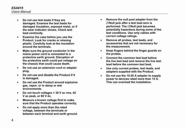
• Do not use test leads if they are damaged. Examine the test leads for damaged insulation, exposed metal, or if the wear indicator shows. Check test lead continuity.
• Examine the case before you use the Product. Look for cracks or missing plastic. Carefully look at the insulation around the terminals.
• Make sure the ground conductor in the mains power cord is connected to a protective earth ground. Disruption of the protective earth could put voltage on the chassis that could cause death.
• Do not use an extension cord or adapter plug.
• Do not use and disable the Product if it is damaged.
• Do not use the Product around explosive gas, vapor, or in damp or wet environments.
• Do not touch voltages > 30 V ac rms, 42 V ac peak, or 60 V dc.
• Measure a known voltage first to make sure that the Product operates correctly.
• Do not apply more than the rated voltage, between the terminals or between each terminal and earth ground.
• Remove the null post adapter from the ∅/Null jack after a test lead zero is performed. The ∅/Null jack becomes potentially hazardous during some of the test conditions. Use only cables with correct voltage ratings.
• Remove all probes, test leads, and accessories that are not necessary for the measurement.
• Keep fingers behind the finger guards on the probes.
• Connect the common test lead before the live test lead and remove the live test lead before the common test lead.
• Use only current probes, test leads, and adapters supplied with the Product.
• Do not use the 15-20 A adapter to supply power to devices rated more than 15 A. This can overload the installation.

Electrical Safety Analyzer Unpack the Product
5
• Replace the mains power cord if the insulation is damaged or if the insulation shows signs of wear.
• Comply with local and national safety codes. Use personal protective equipment (approved rubber gloves, face protection, and flame-resistant clothes) to prevent shock and arc blast injury where hazardous live conductors are exposed.
• Do not touch metal parts of the device under test (DUT) while you do a test. Some tests apply high voltage and high current to the DUT with the DUT earth connection open or closed.
Unpack the Product Carefully unpack all items from the box and check that you have these items:
• ESA615
• Getting Started Manual
• Users Manual CD
• Carrying case
• Power cord
• 15 – 20 A Adapter (USA only)
• ESA USA Accessory Kit (USA, Australia, and Israel only) or ESA EUR Accessory Kit
• Ansur Demo CD
• Null Post Adapter
• 5-to-5 Banana to ECG Adapter (BJ2ECG)
• USB Transfer Cable

ESA615 Users Manual
6
Instrument Familiarization Figure 1 and Table 2 show the front-panel controls and connections of the Product.
2
3
7
8
91
4
5
6
gtv116.eps
Figure 1. Front-Panel Controls and Connections

Electrical Safety Analyzer Instrument Familiarization
7
Table 2. Top-Panel Controls and Connections
Item Name Description
1 Equipment Outlet Configuration Buttons
Controls the configuration of the equipment outlet. Opens and closes the neutral and ground connection and reverses the polarity of the neutral and hot connection.
2 High Voltage Indicator Illuminates when high voltage is applied to the ECG/Applied Parts posts or L1 and L2 of the Test Receptacle.
3 Test Function Buttons Selects the Product test functions.
4 Navigation Buttons Cursor control buttons for navigating menus and lists.
5 Test Button Starts selected tests.
6 Enter Button Sets the highlighted function.
7 Input Jacks Test lead connectors.
8 Nulling Jack Connection to zero test lead resistance.
9 Function Softkeys Keys F1 through F4 are used to select from a number of selections that show in the LCD display above each function softkey.
ESA615 Users Manual
8
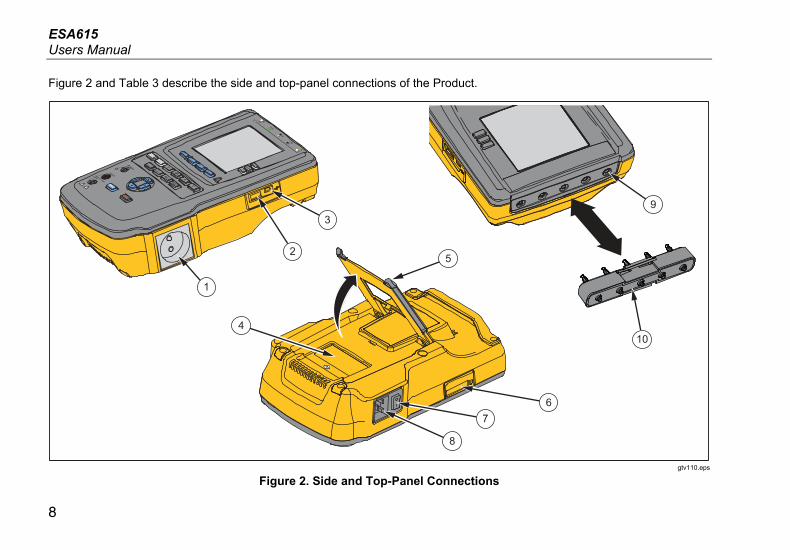
Figure 2 and Table 3 describe the side and top-panel connections of the Product.
RA
LL
LA
RL
V1
R
F
L
N
C1
3
2
9
10
1
8
76
4
5
gtv110.eps
Figure 2. Side and Top-Panel Connections

Electrical Safety Analyzer Instrument Familiarization
9
Table 3. Side and Top-Panel Connections
Item Name Description
1 Equipment Outlet Equipment outlet, specified to the version of the Product, which supplies a DUT connection.
2 USB A Controller Port For external keyboard or barcode reader.
3 USB Device Port
(Mini B-style connector)
Digital connection to control the Product from a PC or instrument controller.
4 Fuse Access Door Equipment outlet fuse access.
5 Tilt Stand Holds the Product in a tilted position.
6 SD Card Slot SD Memory Card access
7 AC Power Switch Turns ac power on and off.
8 Power Input Connector A grounded male three-prong (IEC 60320 C19) connector that accepts the line-power cord.
9 ECG/Applied Parts Jacks Connection posts for Device Under Test (DUT) applied parts, such as ECG leads. Used to test for leakage current through leads and to supply ECG signals and performance waveforms to a DUT.
10 Banana Jack to ECG Adapter Adapter to connect ECG snap leads to the Product.
ESA615 Users Manual
10
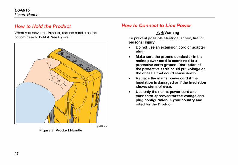
How to Hold the Product When you move the Product, use the handle on the bottom case to hold it. See Figure .
gtv122.eps
Figure 3. Product Handle
How to Connect to Line Power
Warning
To prevent possible electrical shock, fire, or personal injury:
• Do not use an extension cord or adapter plug.
• Make sure the ground conductor in the mains power cord is connected to a protective earth ground. Disruption of the protective earth could put voltage on the chassis that could cause death.
• Replace the mains power cord if the insulation is damaged or if the insulation shows signs of wear.
• Use only the mains power cord and connector approved for the voltage and plug configuration in your country and rated for the Product.

Electrical Safety Analyzer How to Connect a DUT to the Product
11
The Product is intended for use with single-phase, grounded power. It is not intended for dual, split-phase or three-phase power configurations. It can be used with a power system that supplies the correct voltages for single-phase and is grounded, or is an isolated power system.
Use the power cord for your country mains supply that is not more than the voltage or power rating of the product. Connect the cord into the power input connector and then to the mains outlet.
How to Connect a DUT to the Product You can connect a Device Under Test (DUT) a number of different ways for a full electrical safety test. Figure shows a DUT connected to the test receptacle, applied parts posts, and a connection to the enclosure or protective earth ground of the DUT.
How to Turn On the Product
Note
To make sure the high voltage indicator works, look for it to illuminate at the power-up.
Push the power switch found on the left-side panel so the “I” side of the ac power switch is down. The Product does a series of self tests and then shows the message in Figure when the self test has completed successfully.
gtv125.bmp
Figure 4. Product Ready for Operation

ESA615 Users Manual
12
RA
LL
LA
RL
V1
R
F
L
N
C1
To protective earth or any exposed conductive surface on the enclosure
Connect ESA615 to grounded mains socket.
Connect the DUT ac power cord to theequipment outlet on the Analyzer
gtv113.eps
Figure 5. DUT Connections to the Product

Electrical Safety Analyzer How to Access the Product Functions
13
The self-test measures the ac mains input for correct polarity, ground integrity and voltage level. The high voltage indicator illuminates briefly during the self test. If the polarity is reversed, the Product shows this condition and sets the polarity to be reversed internally. If the ground is open, the Product shows this fault. If the mains voltage is too high or too low, the Product shows this fault and does not continue until the supply voltage is corrected and the Product power turned off and then on again.
How to Access the Product Functions For each test and setup function, the Product uses a series of menus to access different Product tests and setup variables. The example shown in Figure , the Product shows different leakage current tests along the bottom of the display. A More softkey lets you access more menus related to the test. When you push a softkey (F1 through F4) below a test name, the Product sets up for or does the selected test.
For some tests, it will be necessary to set parameters with the navigation buttons. In the example above, the leakage parameter has next to it. This icon shows you must push or to set its value. In this example, the leakage current measurement changes between AC+DC, AC only, or DC only. The applied parts indicator has on the left end and on the right end. These icons show that you must push and to set an applied part.

ESA615 Users Manual
14
gtv102.bmp
Figure 6. Leakage Current Menu
The three buttons along the right side of the display () control the wiring of the Product’s test receptacle for some electrical tests. The current condition of these three buttons is shown along the right edge of the display when these controls are active.
Figure 5 shows polarity is settable between normal, reversed, and off. Neutral is also settable to closed or open. Earth condition is not shown, which means it can not be changed. Earth is internally opened while the Product does this test.
How to Connect a PC to the Product To connect the Product to a PC:
Connect a USB port on your PC or laptop to the Mini B USB device port on the Product.
Or
Plug in an XStick wireless USB dongle to your PC USB port. Products available over wireless will be listed by serial number. Connect to a single Product. See Figure 7.

Electrical Safety Analyzer How to Connect a PC to the Product
15
RA
LL
LA
RL
V1
R
F
L
N
C1
RA
LL
LA
RL
V1
R
F
L
N
C1
gtv129.bmp
Figure 7. Product to PC Connection
ESA615 Users Manual
16
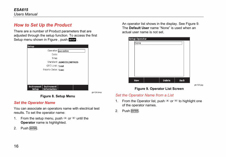
How to Set Up the Product There are a number of Product parameters that are adjusted through the setup function. To access the first Setup menu shown in Figure , push .
gtv124.bmp
Figure 8. Setup Menu
Set the Operator Name
You can associate an operators name with electrical test results. To set the operator name:
1. From the setup menu, push or until the Operator name is highlighted.
2. Push .
An operator list shows in the display. See Figure 9. The Default User name “None” is used when an actual user name is not set.
gtv123.jpg
Figure 9. Operator List Screen
Set the Operator Name from a List
1. From the Operator list, push or to highlight one of the operator names.
2. Push .

Electrical Safety Analyzer How to Set Up the Product
17
Set a New Operator Name
1. From the Operator list, push the New softkey.
Note
The Product keeps a maximum of 20 operator names. If you push the New softkey and there are already 20 names, the Product will show an error. You will have to delete one or more names to add a new name.
2. In the keyboard screen, push , , , or to move the highlight to a character.
3. Push to add the highlighted character to the name field.
Note
You can push the F2 softkey to set the keyboard between upper and lower case letters. Highlight àéîöç and push to toggle between accent characters and standard alpha-numeric letters.
4. Do steps 2 and 3 again until the operator name is complete.
5. Push the Done softkey.
Note
Push the Backspace softkey to delete the last character in the name field.
Delete an Operator Name
To delete an operator name:
1. From the setup menu, push or until the Operator name is highlighted.
2. Push .
3. From the Operator list, push or to highlight one of the operator names.
4. Push the Delete softkey.
5. A delete confirmation screen will show in the display.
6. Push the Delete softkey.

ESA615 Users Manual
18
Set the Date
From the setup menu, push or until the Date value is highlighted.
1. Push .
2. In the keyboard screen, push or to move the highlight to a character.
3. Push .
4. Do steps 2 and 3 again until the date is complete.
5. Push the Done softkey.
Note
Push the Backspace softkey to delete the last character in the date field.
Set the Time
1. From the setup menu, push or until the Time value is highlighted.
2. Push .
3. In the Keyboard screen, push or to move the highlight to a character.
4. Push .
5. Do steps 3 and 4 again until the time is complete.
Note
When you set the time for 12-hour format, push the am/pm softkey to set AM or PM.
6. Push the Done softkey.
Note
Push the Backspace softkey to delete the last character in the date field.
Set the Test Standard
1. From the setup menu, push or until the Standard variable is highlighted.
2. Push .
3. Push or to highlight one of the standards.
4. Push .
Set the GFCI Limit
To set the GFCI current limit:
5. From the setup menu, push or until the GFCI Limit variable is highlighted.
6. Push .
7. Push or to highlight one of the preset GFI current values.
8. Push .

Electrical Safety Analyzer How to Set Up the Product
19
Set Polarity Switching Delay
When the test receptacle of the Product is switched, a delay can be set to control the actual switch time. To set the polarity delay:
1. From the setup menu, push or until the Polarity Delay variable is highlighted.
2. Push .
3. Push or to highlight one of the preset delay values.
4. Push .
Set the Date Format
1. From the setup menu, push the Instrument Setup softkey.
2. Push or until the Date Format variable is highlighted.
3. Push .
4. Push or to highlight DD/MM/YYYY, MM/DD/YYYY, or YYYY/MM/DD.
5. Push .
Set the Time Format
1. From the setup menu, push the Instrument Setup softkey.
2. Push or until the Time Format variable is highlighted.
3. Push .
4. Push or to highlight 12 Hour or 24 Hour.
5. Push .
Set the Language
The Product can display data in English, French, German, Spanish, Italian, or Portuguese. To change the language:
1. From the setup menu, push the Instrument Setup softkey.
2. Push or until the Language variable is highlighted.
3. Push .
4. Push or to highlight one of the languages.
5. Push .
ESA615 Users Manual
20
Set the Beeper
To enable or disable the beeper:
1. From the setup menu, push the Instrument Setup softkey.
2. Push or until the Beeper variable is highlighted.
3. Push .
4. Push or to highlight Off or On.
5. Push .
Set the Display Contrast
There are two procedures to set the display contrast. From the Test Sequence start-up menu or through the setup menu.
When the Product shows its start-up menu (Select a test…), push or to increase or decrease the display contrast respectively. Push the Done softkey to exit contrast setup.
To adjust the contrast through the setup menu:
1. From the setup menu, push the Instrument Setup softkey.
2. Push the Display Contrast softkey.
3. Push or to increase or decrease the display contrast respectively.
4. Push the Done softkey to exit contrast setup.
How to View Instrument Information To show model number, serial number, firmware version, and last calibration date of the Product, push . Next push the Instrument Information softkey.
How to Do Electrical Safety Tests The Product does a number of different electrical and performance tests on biomedical equipment. The sections that follow are test descriptions with instructions on how to do them with the Product.

Electrical Safety Analyzer How to Do Electrical Safety Tests
21
Set the Test Standard
The electrical safety tests in the Product are specified by different safety standards: AAMI ES1/NFPA99, IEC62353, IEC60601-1, and AN/NZS 3551. AAMI is set as the default standard. To select different standard:
1. From the setup menu, push until the Standard variable is highlighted.
2. Push .
3. Push or to highlight one of the standards.
4. Push .
Not all electrical tests are applicable for all standards. In these cases, the menu only shows the tests that are specified in the set standard.
Note
The standard set in the setup menu applies to all manual measurement modes. The automated tests use the standard set for the selected test sequence.
Mains Voltage Test
The Mains Voltage test measures the voltage on the mains input through three measurements. To access the Mains Voltage test, push . The Mains Voltage test menu is shown in Figure .
gtv104.bmp
Figure 10. Mains Voltage Test Menu
Push each function softkey to do each of the three measurements: Live to neutral, neutral to ground, and live to ground.
Note
Power is removed from the test receptacle while the Product does a Mains Voltage test.

ESA615 Users Manual
22
Ground Wire (Protective Earth) Resistance Test
The Ground Wire (Protective Earth) Resistance test measures the impedance between the PE terminal of the test receptacle and the exposed conductive parts of the DUT that are connected to the Protective Earth of the DUT.
Note
Before you do leakage tests with the Product, it is best to make sure the ground connection is good.
Do this test between the test receptacle ground and the Protective earth ground of the DUT or DUT enclosure.
To access the Ground Wire (Protective Earth) ∅/Null Resistance Test menu push .
Note
The DUT is turned off for this test.
To do a ground wire resistance test:
1. Make sure the power cord from the DUT is connected into the test receptacle.
2. Push to reveal the resistance function menu.
3. Connect one end of a test lead to the V/Ω/A jack.
4. If you use an accessories probe, connect it to the other end of the test lead and put the probe tip into the ∅/Null jack. If you use an alligator clip accessory,
connect it to the other end of the test lead, put the null post adapter in the ∅/Null jack, and clamp the alligator clip to the null post adapter.
Note
The ∅/Null jack does not accept the test leads supplied with the Product.
5. Push the Zero Leads softkey. The Product zeroes out the measurement to cancel the test lead resistance.
6. Connect the test lead from the V/Ω/A jack to the DUT enclosure or protective earth connection.

Electrical Safety Analyzer How to Do Electrical Safety Tests
23
7. After you make the connections to the DUT, the measured resistance shows in the display. See Figure .
gtv105.jpg
Figure 11. DUT Ground Resistance Measurement
Warning
To prevent electrical shock, remove the null post adapter from the ∅/Null jack after a test lead zero is performed. The ∅/Null jack becomes potentially hazardous during some of the test conditions.
A low resistance measurement is necessary to make sure there is a good ground connection through the power cord. Refer to the applicable electrical safety standard for the specified limit value to be followed.
Figure shows the electrical connections between the Product and the DUT. Table 4 is a list of the abbreviations used in the schematics and their descriptions.

ESA615 Users Manual
24
RA
LL
LA
RL
V1
R
F
L
N
C1
To protective earth or any exposed conductive surface on the enclosure
Connect the DUT ac power cord to theequipment outlet on the Analyzer
gtv112.eps
Figure 12. Ground Wire (Protective Earth) Resistance Measurement Connections

Electrical Safety Analyzer How to Do Electrical Safety Tests
25
Table 4. Schematic Abbreviations
Abbreviation Meaning
MD Measurement Device (ESA615 Analyzer)
FE Functional Earth
PE Protective Earth
Mains Mains voltage supply
L1 Live conductor
L2 Neutral conductor
DUT Device Under Test
DUT_L1 Device Under Test live conductor
DUT_L2 Device Under Test neutral conductor
DUT_PE Device Under Test Protective Earth
REV POL Reversed mains supply polarity
LEAD GND Lead to ground, used in patient leakage test
MAP Mains on Applied Part
MAP REV Reverse Mains on Applied Part source voltage
PE Open Open Protective Earth
Test voltage

ESA615 Users Manual
26
MD
TEST LEAD
CONDUCTIVE PART
DUT_PE FE
DUT_L2
DUT_L1DEVICE UNDER TEST
APPLIEDPART
faw26.eps
Figure 13. Ground Wire (Protective Earth) Resistance Measurement Schematic

Electrical Safety Analyzer How to Do Electrical Safety Tests
27
Insulation Resistance Test
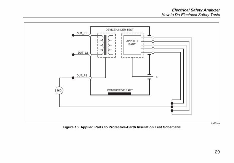
The five Insulation Resistance Tests measure mains (L1 & L2) to Protective earth, applied parts to Protective earth, mains to applied parts, mains to non-earthed conductive points, and applied parts to non-earthed conductive points.
To access the Insulation Resistance Test menu, push .
All Insulation Resistance Tests can be done with 500 V dc or 250 V dc. To change the test voltage from the Insulation Resistance Test menu, push the More softkey. Push the Change Voltage softkey to toggle the test voltage between 250 V dc and 500 V dc.
Note
When you exit and re-enter the Insulation Resistance Test menu, the test voltage is set to its default value of 500 V dc.
As shown in Figure , three of the five tests are shown above function softkeys F1 through F3. To access the other two tests or test voltage selection, push the More softkey. The Back softkey will move the menu up to the top-level Insulation Resistance test menu.
gtv106.jpg
Figure 14. Insulation Resistance Measurement
After you push a test softkey, push to apply the test voltage to the DUT and take the resistance measurement.
Figures through shows the electrical connections between the Product and DUT for the five Insulation Resistance tests.
Note
The DUT is powered off for this test.

ESA615 Users Manual
28
MD
CONDUCTIVE PART
DUT_PE
DUT_L2
DUT_L1
FE
DEVICE UNDER TEST
APPLIEDPART
faw17.eps
Figure 15. Mains to Protective-Earth Insulation Resistance Test Schematic
Electrical Safety Analyzer How to Do Electrical Safety Tests
29
MD CONDUCTIVE PART
DUT_PE
DUT_L2
DUT_L1
FE
DEVICE UNDER TEST
APPLIEDPART
faw18.eps
Figure 16. Applied Parts to Protective-Earth Insulation Test Schematic

ESA615 Users Manual
30
MD
CONDUCTIVE PART
DUT_PE
DUT_L2
DUT_L1
FE
DEVICE UNDER TEST
APPLIEDPART
faw19.eps
Figure 17. Mains to Applied-Parts Insulation Test Schematic

Electrical Safety Analyzer How to Do Electrical Safety Tests
31
MD
CONDUCTIVE PART
DUT_PE
DUT_L2
DUT_L1
FE
DEVICE UNDER TEST
APPLIEDPART
TESTLEAD
faw20.eps
Figure 18. Mains to Non-Earth Accessible Conductive Points Schematic

ESA615 Users Manual
32
MD
CONDUCTIVE PART
DUT_PE
DUT_L2
DUT_L1
FE
DEVICE UNDER TEST
APPLIEDPART
TESTLEAD
faw21.eps
Figure 19. Applied Parts to Non-Earth Conductive Points Schematic

Electrical Safety Analyzer How to Do Electrical Safety Tests
33
Equipment Current Test
To measure the current consumed by the DUT, push . The Product shows the current that flows through the mains connections of the test receptacle.
Leakage Current Test
The Product measures leakage current for different DUT configurations. The Product measures leakage found on the enclosure and the earth connection as well as leakage
on each connected applied part and combinations of connected applied parts.
The available leakage tests are set by the standard you set in setup. See the How to Set the Test Standard section to change the test standard.
Table is a list of six leakage current tests. Their names are different when the standard is changed in the Product.
Push to access the leakage current main menu shown in Figure .
Table 5. Test Names Based on Selected Standard
IEC60601 AAMI/NFPA 99
Protective Earth Resistance Ground Wire Resistance
Earth Leakage Current Ground Wire Leakage Current
Touch or Enclosure Leakage Current Chassis Leakage Current
Patient Leakage Current Lead to Ground Leakage Current
Patient Auxiliary Leakage Current Lead to Lead Leakage Current
Mains on Applied Part (MAP) Leakage Current Isolation Leakage Current

ESA615 Users Manual
34
gtv102.bmp
Figure 20. Leakage Current Main Menu
Note
The display shown in Figure is the main leakage current menu when AAMI is the standard.
All leakage currents but Lead Isolation (Mains on Applied parts), are shown in as AC+DC, AC Only, or DC only. The initial result is shown in the applicable parameter for the set test standard. To change the parameter, push or . The measurement method is shown to the right of the current measurement while leakage current tests are done.
Earth Leakage Current
Note
The Ground Wire (Earth) Leakage test is available for AAMI, 60601, and not IEC 62353.
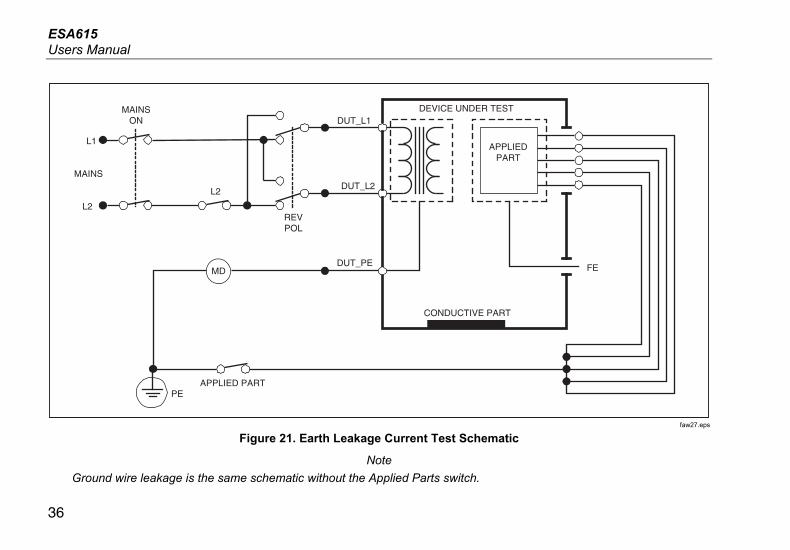
To measure the current that flows in the protective earth circuit of the DUT, push the Ground Wire softkey from the leakage current main menu. Figure shows the electrical connections between the Product and the DUT when you do a Ground Wire Leakage Current Test.
The Ground Wire Leakage Current test has some combination measurements that can be done. Push to switch the polarity of the mains voltage applied to the test receptacle between Normal, Off, Reverse, and Off. Push to open and close the neutral connection to the test receptacle. It is not necessary to open up the test receptacle earth (ground), since this is done internally by the measurement.

Electrical Safety Analyzer How to Do Electrical Safety Tests
35
The outlet conditions below apply when you do this test:
• Normal Polarity
• Normal Polarity, Open Neutral
• Reversed Polarity
• Reversed Polarity, Open Neutral
IEC60601-1 specifies that the applied parts must be connected for this measurement. Push or to ground and unground all applied parts connection posts.
Note
A ground connection on an applied part is shown as a box around the applied part in the display.
ESA615 Users Manual
36
CONDUCTIVE PART
DUT_PE
APPLIED PARTPE
L2
DUT_L2
DUT_L1
MAINS
L1
L2
REVPOL
MAINSON
MD FE
DEVICE UNDER TEST
APPLIEDPART
faw27.eps
Figure 21. Earth Leakage Current Test Schematic
Note
Ground wire leakage is the same schematic without the Applied Parts switch.

Electrical Safety Analyzer How to Do Electrical Safety Tests
37
Chassis (Enclosure) Leakage Test
Note
The Chassis (Enclosure) Leakage test is only available for the IEC60601 or ANSI/AAMI ES1 1993 standard selections.
The Chassis (Enclosure) Leakage Test measures the current that flows between the enclosure of the DUT and protective earth. Figure shows the electrical connections between the Product and the DUT.
To do a Chassis (Enclosure) Leakage Test:
1. Connect a lead between the V/Ω/A jack and the DUT enclosure.
2. Push .
3. Push the Chassis softkey from the Leakage Current Test menu.
4. The measured current shows in the display.
The Chassis Leakage test can be done with different fault conditions on the test receptacle. Push to switch the test receptacle between Normal, Off, Reverse, and Off. Push to open and close the neutral connection to the receptacle. Push to open and close the earth connection of the receptacle.
The outlet conditions below apply when do this test:
• Normal Polarity
• Normal Polarity, Open Earth
• Normal Polarity, Open Neutral
• Reversed Polarity
• Reversed Polarity, Open Earth
• Reversed Polarity, Open Neutral
IEC60601-1 specifies that the applied parts must be connected for this measurement. Push or to ground and unground all applied parts connection posts.
Note
Chassis leakage for ANSI/AAMI is the same schematic without the Applied Parts switch.

ESA615 Users Manual
38
CONDUCTIVE PART
DUT_PE
APPLIED PART
TEST LEAD
PE
L2
DUT_L2
DUT_L1
MAINS
L1
EARTH
MAINSON
L2
MD
FE
DEVICE UNDER TEST
APPLIEDPART
faw28.eps
Figure 22. Enclosure Leakage Current Test Schematic
Electrical Safety Analyzer How to Do Electrical Safety Tests
39
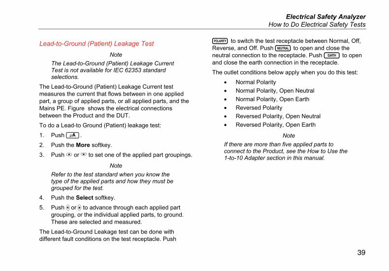
Lead-to-Ground (Patient) Leakage Test
Note
The Lead-to-Ground (Patient) Leakage Current Test is not available for IEC 62353 standard selections.
The Lead-to-Ground (Patient) Leakage Current test measures the current that flows between in one applied part, a group of applied parts, or all applied parts, and the Mains PE. Figure shows the electrical connections between the Product and the DUT.
To do a Lead-to Ground (Patient) leakage test:
1. Push .
2. Push the More softkey.
3. Push or to set one of the applied part groupings.
Note
Refer to the test standard when you know the type of the applied parts and how they must be grouped for the test.
4. Push the Select softkey.
5. Push or to advance through each applied part grouping, or the individual applied parts, to ground. These are selected and measured.
The Lead-to-Ground Leakage test can be done with different fault conditions on the test receptacle. Push
to switch the test receptacle between Normal, Off, Reverse, and Off. Push to open and close the neutral connection to the receptacle. Push to open and close the earth connection in the receptacle.
The outlet conditions below apply when you do this test:
• Normal Polarity
• Normal Polarity, Open Neutral
• Normal Polarity, Open Earth
• Reversed Polarity
• Reversed Polarity, Open Neutral
• Reversed Polarity, Open Earth
Note
If there are more than five applied parts to connect to the Product, see the How to Use the 1-to-10 Adapter section in this manual.

ESA615 Users Manual
40
LEADSELECTRELAY*
LEAD GNDSELECT RELAY(REMOTE ONLY)
CONDUCTIVE PART
DUT_PE
PE
PE
L2
DUT_L2
DUT_L1
MAINS
L1
EARTH
L2
REVPOL
MAINSON
MD
FE
DEVICE UNDER TEST
APPLIEDPART
*Leads not selected are open.
gtv29.eps
Figure 23. Lead-to-Ground (Patient) Leakage Current Test Schematic

Electrical Safety Analyzer How to Do Electrical Safety Tests
41
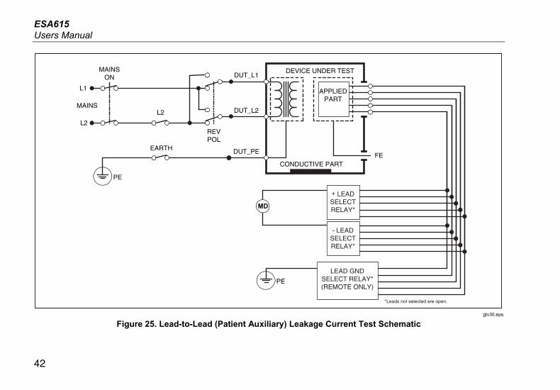
Lead-to-Lead (Patient Auxiliary) Leakage Tests
Note
The Lead-to-Lead (Patient Auxiliary) leakage test is available when the IEC60601 or ANSI/AAMI ES1-1993 standard is selected.
To measure the leakage current through each applied part or lead and combination of lead connections (all other or between two), push the Lead to Lead softkey from the Leakage Test main menu shown in Figure . Figure shows the electrical connections between the Product and the DUT when it does a Lead-to-Lead (Patient Auxiliary) Leakage Current Test.
The Lead-to-Lead (Patient Auxiliary) Leakage test adds a diagram of the applied parts connection posts to the display, as shown in Figure . In the figure, the applied parts post RA/R is shown above the other posts. This shows that the leakage measurement is from RA/R to all others. To move to the subsequent applied part post, push . The first post will show inline with the other posts while the LL/F post shows above all others. This shows the second leakage measurement is from LL/F to all others. Continue to push or to move from one connection post to another.
After each post is isolated individually, the Lead-to-Lead (Patient Auxiliary) Leakage test measures current of three
different combinations of posts tied together: RA/R and LL/F, RA/R and LA/L, or LL/F and LA/L.
fis107.eps
Figure 24. Applied Parts Connection Posts Display
The Lead-to-Lead (Patient Auxiliary) Leakage test can make different fault measurements. Push to switch the polarity of the mains voltage applied to the test receptacle between Normal, Off, Reverse, and Off. Push to open and close the neutral connection to the test receptacle. Push to open and close the earth or ground connection to the test receptacle.
Note
If there are more than five applied parts to connect to the Product, see the How to Use the 1-to-10 Adapter section in this manual.
ESA615 Users Manual
42
+ LEADSELECTRELAY*
- LEADSELECTRELAY*
CONDUCTIVE PART
DUT_PE
PE
PE
L2
DUT_L2
DUT_L1
MAINS
L1
EARTH
L2
MAINSON
REVPOL
FE
DEVICE UNDER TEST
APPLIEDPART
MD
LEAD GNDSELECT RELAY*(REMOTE ONLY)
*Leads not selected are open.
gtv30.eps
Figure 25. Lead-to-Lead (Patient Auxiliary) Leakage Current Test Schematic

Electrical Safety Analyzer How to Do Electrical Safety Tests
43
The outlet conditions below apply when you do this test:
• Normal Polarity
• Normal Polarity, Open Neutral
• Normal Polarity, Open Earth
• Reversed Polarity, Open Neutral
• Reversed Polarity, Open Earth
Lead Isolation (Mains on Applied Part) MAP Leakage Test
Note
The Lead Isolation (Mains on Applied Part) leakage test is available when the IEC60601 & ANSI/AAMI standard is selected.
The Lead Isolation (Mains On Applied Parts) Leakage Current test measures the current that flows in response to an isolated AC voltage applied between a selected applied part, group of applied parts, or all applied parts, and Earth (and any conductive part connected to the RED terminal). Figure shows the electrical connections between the Product and the DUT when it does a Mains on Applied Part Leakage Current Test.
Note
With 60601 standard selected, the MAP test voltage is available in Normal and Reverse (180 degrees out of phase with mains).
To do a Lead Isolation (Mains on Applied Part) test:
1. Push .
2. Push the More softkey.
3. Set the applied part groupings with and .
Note
Refer to the test standard when you decide the type of the applied parts and how they must be grouped for the test.
4. Push the Select softkey.
5. Push the Lead Isolation softkey.
6. Push or to set the desired applied part connection.
7. Push to apply the voltage and read the leakage current in the display.

ESA615 Users Manual
44
Push and to scroll through the applied part connections or groupings. Push for each connection configuration to thoroughly test the DUT.
The outlet conditions below apply when you do this test:
• Normal Polarity
• Reverse Polarity
Note
If there are more than five applied parts to connect to the Product, see the How to Use the 1-to-10 Adapter section in this manual.

Electrical Safety Analyzer How to Do Electrical Safety Tests
45
DUT_PE
PE
L2
DUT_L2
DUT_L1
MAINS
L1
MAINSOn
REVPOL
MAPREV
MD
MAP (ISOLATION)TRANSFORMER
FE
LEADSELECTRELAY*
APPLIEDPART
*Leads not selected are open.
CONDUCTIVE PART
DEVICE UNDER TEST
TESTLEAD
gtv31.eps
Figure 26. Lead Isolation (Mains On Applied Parts) Leakage Test Schematic

ESA615 Users Manual
46
Alternative Equipment Leakage Test
Note
The alternative equipment leakage test is available when the EN62353 standard is selected.
The Alternative Equipment Leakage test, applies the voltage source between short-circuited equipment outlet mains live, neutral, and equipment outlet earth, the exposed conductive surface on the housing, and all applied parts short-circuited together. The test disconnects equipment from mains. The current which flows over the insulation of the DUT is measured.
This test is not applicable for equipment with internal electrical power source. The switches in mains part must be closed for this measurement.
To do an alternative equipment leakage test:
1. Push .
2. Push the Alternative Equipment softkey.
3. Push to apply the voltage and read the current in the display.
Figure shows the electrical connections between the Product and the DUT for the Alternative Equipment Leakage Test.
The outlet conditions below apply when you do this test:
• Closed Earth
• Open Earth
Note
If there are more than five applied parts to connect to the Product, see the How to Use the 1-to-10 Adapter section in this manual.
Alternative Applied Part Leakage Test
Note
The Alternative applied part leakage test is available when the EN62353 standard is selected.
The Alternative Applied Part Leakage test applies the test voltage between short-circuited applied parts of a single function and the short-circuited equipment outlet mains live, neutral, earth, and exposed conductive surface on the housing. This test should only be done for equipment with F-Type applied parts. For equipment with multiple applied parts, test each group of applied parts of a single function in turn with all others float during the test. All applied parts can be connected to the applied parts jacks and the lead selection will float those not selected.

Electrical Safety Analyzer How to Do Electrical Safety Tests
47
CONDUCTIVE PARTDUT_PE
DUT_L2
DUT_L1
FE
DEVICE UNDER TEST
APPLIEDPART
TESTLEAD
MD
faw22.eps
Figure 27. Alternative Equipment Leakage Current Test Schematic

ESA615 Users Manual
48
To do an alternative applied part leakage test:
1. Push .
2. Push the More softkey.
3. Set the applied part groupings with and .
4. Push the Select softkey.
5. Push the Alternative A.P. softkey.
6. Push to apply the test voltage and read the current in the display.
7. Push or to advance to the next applied part group(s) of a single function if applicable. Push to read leakage current for each group.
Figure shows the electrical connections between the Product and the DUT for an Alternative Applied Part Leakage current test.
Note
If there are more than five applied parts to connect to the Product, see the How to Use the 1-to-10 Adapter section in this manual.
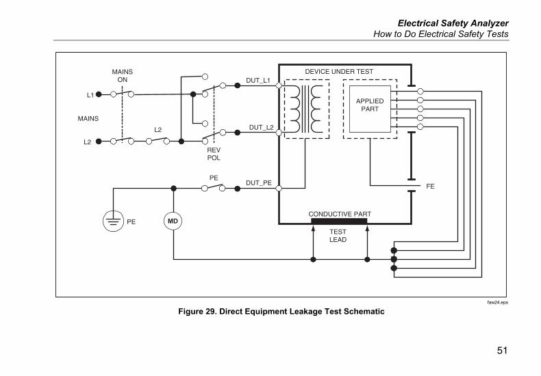
Direct Equipment Leakage Test
Note
The Direct Equipment Leakage test is available when the EN62353 standard is selected.
The Direct Equipment Leakage Current test measures the leakage current between all applied parts and the exposed conductive surface on the housing to mains earth.
To do a direct equipment test:
1. Push .
The direct equipment test is the default test and must already be selected.
2. Push to apply the voltage and read the leakage current in the display
Figure shows the electrical connections between the Product and the DUT for a Direct Equipment Leakage Current Test.
The outlet conditions below apply when you do this test:
• Normal Polarity, Closed Earth
• Normal Polarity, Open Earth
• Reversed Polarity, Closed Earth
• Reversed Polarity, Open Earth
Note
If there are more than five applied parts to connect to the Product, see the How to Use the 1-to-10 Adapter section in this manual.

Electrical Safety Analyzer How to Do Electrical Safety Tests
49
CONDUCTIVE PART
DUT_PE
DUT_L2
DUT_L1
FE
DEVICE UNDER TEST
APPLIEDPART
LEADSELECTRELAY*
*Leads not selected are open.
TESTLEAD
MD
gtv23.eps
Figure 28. Alternative Applied Part Leakage Test Schematic

ESA615 Users Manual
50
Direct Applied Part Leakage Test
Note
The Direct Applied Part Leakage test is available when the EN62353 standard is selected.
The Direct Applied Part Leakage Current test measures the leakage current between all applied parts of one function and the exposed conductive surface on the housing, to mains earth. For equipment with multiple applied parts, you must do the test on each group of one function each in turn while all others float. This test must only be done for equipment with F-Type applied parts.
For Type B applied part, see direct equipment leakage schematic in Figure .
To do a direct applied part leakage test:
1. Push .
2. Push the More softkey.
3. Set the desired applied part groupings with and .
4. Push the Select softkey. The Direct A.P. test must already be set.
5. Push or to set the applied part test configuration.
6. Push to apply the test voltage and read the current in the display.
7. Push or to advance to the next group of applied parts, if applicable.
Figure shows the electrical connections between the Product and the DUT for a Direct Applied Part Leakage Current Test.
The outlet conditions below apply when you do this test:
• Normal Polarity
• Reversed Polarity
Note
If there are more than five applied parts to connect to the Product, see the How to Use the 1-to-10 Adapter section in this manual.
Electrical Safety Analyzer How to Do Electrical Safety Tests
51
CONDUCTIVE PART
DUT_PE
L2
DUT_L2
DUT_L1
MAINS
L1
L2
MAINSON
REVPOL
PE
PE
TESTLEAD
FE
DEVICE UNDER TEST
APPLIEDPART
MD
faw24.eps
Figure 29. Direct Equipment Leakage Test Schematic

ESA615 Users Manual
52
LEADSELECTRELAY*
*Leads not selected are open.
CONDUCTIVE PART
DUT_PE
L2
DUT_L2
DUT_L1
MAINS
L1
L2
PE
MAINSON
REVPOL
FE
DEVICE UNDER TEST
APPLIEDPART
MD
gtv25.eps
Figure 30. Direct Applied Parts Leakage Current Test Schematic

Electrical Safety Analyzer How to Do Electrical Safety Tests
53
Differential Leakage Current Test
Note
The Differential Leakage Current test is available when the EN62353 standard is selected.
The differential leakage current test measures the magnitudes of the differential current that flows in the Equipment Outlet live and neutral, with power applied to the equipment outlet. All applied parts must be connected for this test, if equipment has applicable applied parts.
To do a differential leakage current test:
1. Push .
2. Push the Differential softkey.
Figure shows the electrical connections between the Product and the DUT for a Differential Leakage Current test.
The outlet conditions below apply when you do this test:
• Normal Polarity, Closed Earth
• Normal Polarity, Open Earth
• Reversed Polarity, Closed Earth
• Reversed Polarity, Open Earth
Note
If there are more than five applied parts to connect to the Product, see How to Use the 1-to-10 Adapter later in this manual.

ESA615 Users Manual
54
CONDUCTIVE PART
DUT_PE
PE
L2
DUT_L2
DUT_L1
MAINS
L1
EARTH
TESTLEAD
MAINSON
REVPOL
FE
DEVICE UNDER TEST
APPLIEDPARTMD
gtv32.eps
Figure 31. Differential Leakage Current Test Schematic

Electrical Safety Analyzer How to Use the 1-to-10 Adapter
55
How to Use the 1-to-10 Adapter The 1-to-10 Adapter, an optional accessory, increases the number of lead or applied parts connections to the Product from 5 to 14. The adapter connects a maximum of 10 leads together into a one lead that is connected to one of the input jacks of the Product. The other four Product input jacks can also be used in conjunction with the Adapter. More leads can be added with multiple 1-to-10 Adapters.
The example in Figure shows one application of the Adapter. The Defibrillator/Monitor in the example has 10 ECG leads, two pacer leads, and two defibrillator paddles which must be connected together, and in groups if single function, for current leakage per IEC62353. The example shows the ECG leads to be snap type connectors and two BJ2ECG adapters are shown connected to the Adapter. If the ECG leads do not have snap connectors, then the Universal Snap to Banana Adapter can be used to make the connections to the Adapter.
The common lead from the Adapter is plugged into the RA jack (1st jack) of the Product. Using four sheathed test leads with alligator clips, connect the two defibrillator paddles into the LL and LA Product jacks and the two pacer leads into the RL and V1 jacks. Set the connection that ties all five Product jacks together. This will measure leakage current in all fourteen leads. The applied part group of 1, 2, and 2 lets you test groups of applied parts of one function.

ESA615 Users Manual
56
OFF
DEFIB
PACER
Use leads shortedfor electrical safetytesting only. Do notshort leads for ECGsimulation.
Defibrillator/Pacer ESA615Caution: To prevent damage to the Product, do not apply more than 30 V dc to the AP (ECG). Check unkown connections using a DMM before connecting to ESA615.
1-to-10 andBJ2ECG snap adapters
Alligator Clips
gtv120.eps
Figure 32. 1-to-10 Adapter Connections
Electrical Safety Analyzer How to Use the 1-to-10 Adapter
57
When you do an applied parts test with the AAMI/NFPA-99 standard, the normal connections of RA, LL, LA, and RL are made to their related input jacks. Four adapters from the Universal Snap to Banana Adapter set will be necessary for the first four connections. The other chest leads are connected to the Adapter and the common lead from the Adapter is connected to the V1 jack (5th jack) of the Product. See Figure . This configuration lets you isolate the RA, LL, LA, and RL leads from each other and the other chest leads, which are shorted together, while the Product does the leakage tests.

ESA615 Users Manual
58
Use leads shortedfor electrical safetytesting only. Do notshort leads for ECGsimulation.
ECG Monitor ESA615
1-to-10 andBJ2ECG snap adapters
gtv121.eps
Figure 33. ECG Lead Connection with 1-to-10 Adapter

Electrical Safety Analyzer How to Do Point-To-Point Measurements
59
How to Do Point-To-Point Measurements The Product can make voltage, resistance, and low current measurements through its Point-to-Point function. To access the Point-to-Point function menu shown in Figure , push . Softkeys F1 through F3 are used to set the measurement function.
gtv128.jpg
Figure 34. Point-To-Point Function Menu
Measure Voltage
To make a voltage measurement:
1. Push the Voltage softkey from the Point-To-Point menu.
2. Put test leads in the RED (V/Ω/A ) and BLACK jacks.
3. Put the probe tips across the unknown voltage and read the measurement in the display.
The Product measures a maximum of 300 volts ac.
Measure Resistance
To make a resistance measurement:
1. Push the Resistance softkey from the Point-To-Point menu.
2. Put test leads in the RED (V/Ω/A ) and BLACK jacks.
3. Null lead resistance by shorting the leads together and Push the Zero Leads softkey.
4. Put the probes across the unknown resistance and read the measurement in the display.
The Product measures resistances to a maximum of 2.0 Ω.
ESA615 Users Manual
60
Measure Current
The Product can make dc only, ac only, and ac+dc current measurements to a maximum of 10 mA. To do a current measurement:
1. Push the Leakage softkey from the Point-To-Point menu.
2. Push or set the ac only, dc only, or ac+dc measurement mode.
3. Put test leads in the RED (V/Ω/A ) and BLACK jacks.
4. Put the probe tips on the two points the unknown current may flow and read the measurement in the display.
How to Simulate ECG Waveforms The Product can put different waveforms on the applied parts connection posts. These signals are used to measure the performance parameters of ECG monitors and ECG strip printers. See Figure for the connections between the Product and an ECG monitor. For monitors that use the snap style connectors, put the BJ2ECG adapter into the connectors at the top of the Product and connect the monitor leads to the snap connectors on the adapter.
Note
If the ECG monitor/interpreter has banana posts, use the optional universal snap to banana adapter to connect to the Product.
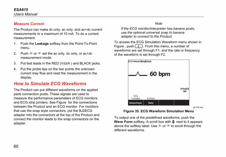
To access the ECG Simulation Waveform menu shown in Figure , push . From this menu, a number of waveforms are set through F1, and the rate or frequency of the waveform is set through F2.
gtv109.bmp
Figure 35. ECG Waveform Simulation Menu
To output one of the predefined waveforms, push the Wave Form softkey. A scroll box with next to it appears above the softkey label. Use or to scroll through the different waveforms.

Electrical Safety Analyzer How to Simulate ECG Waveforms
61
For all waveforms but VFIB and Triangle, the rate or frequency of the waveform is adjusted through the Frequency or Rate softkey. For some waveforms, there are more than two frequency or rate selections. For those waveforms, push the Frequency or Rate softkey to open a scroll box above the softkey label with next to it. Use or to select the frequency or rate. For those waveforms that have only two frequencies or rates, the Frequency or Rate softkey is a toggle, where each push of the softkey switches to the other value.

ESA615 Users Manual
62
RA
LL
LA
RL
V1
R
F
L
N
C1RA
LL
LA
RL
V1
R
F
L
N
C1
ECG Monitor
BJ2ECGAdapter
gtv115.eps
Figure 36. ECG Monitor Connections

Electrical Safety Analyzer Memory
63
Memory The Product keeps test results data and test sequences on an SD memory card. The memory card holds a minimum of 100 test sequences and 1000 test results. Each test result can be recalled to the display of the Product or exported to a PC.
Note
The Product can show the last 200 test results. All results in the Product can be exported to a PC.
To remove the memory card:
1. Push in on the memory card and release it.
2. The memory card will eject out of the slot.
3. Hold the memory card with your fingers and remove it from the product.
Note
With the memory card removed, no test sequences will show in the test library list. You cannot make new test sequence without the card installed in the Product.
To install the memory card:
1. Insert the card with the contacts toward the back.
2. Push the card all the way in until you hear it click.
3. Release the card.
Test Sequences The test sequence feature automates the tests you do on a DUT. You make test sequences with the built-in test sequence wizard. A different procedure is to start with a test sequence that is already in the test library and change it to make a new test sequence. The test sequences and test results are kept on the memory card.
Factory Supplied Test Sequences
Table is a list of factory supplied test sequences that are on the memory card that ships with the Product. Each factory supplied test sequence is prefixed with the test standard number. For example, the 60601-1 Monitor test sequence is based on the 60601-1 test standard.

ESA615 Users Manual
64
Table 6. Factory Supplied Test Sequences
Test Sequence Description [1]
60601 3rd Patient Monitor 3rd Ed., Class I, 5 ECG
60601 3rd Defibrillator 3rd Ed., Class I, 2 Paddles and 3 ECG
60601 3rd Infusion Device 3rd Ed., Class II, 1 No AP
60601 3rd Ultrasound Device 3rd Ed., Class I, 1 Probe
60601 3rd Generic Device 3rd Ed., Class I, No AP
60601 3rd System 3rd Ed., Class I, No AP
62353-Alt. Patient Monitor Class I, 5 ECG
62353-Alt. Defibrillator Class I, 2 Paddles and 3 ECG
62353-Alt. Infusion Device Class II, 1 No-AP
62353-Alt. Ultrasound Device Class I, 1 Probe
62353-Alt. Generic Device Class I, No AP
NFPA99 Patient Monitor Class I, 5 ECG
NFPA99 Defibrillator Class I, 2 Paddles and 3 ECG
NFPA99 Infusion Device Class II, 1 No AP

Electrical Safety Analyzer Test Sequences
65
Table 6. Factory Supplied Test Sequences (cont.)
Test Sequence Description [1]
NFPA99 Ultrasound Device Class I, 1 Probe
NFPA99 Generic Device Class I, No AP
ANSI/AAMI ES-1 Patient Monitor Class I, 5 ECG
ANSI/AAMI ES-1 Defibrillator Class I, 2 Paddles and 3 ECG
ANSI/AAMI ES-1 Infusion Device Class II, 1 No AP
ANSI/AAMI ES-1 Ultrasound Device Class I, 1 Probe
ANSI/AAMI ES-1 Generic Device Class I, No AP
[1] Class designations refer to applicable electrical safety standard definitions for devices, not FDA medical device definitions.
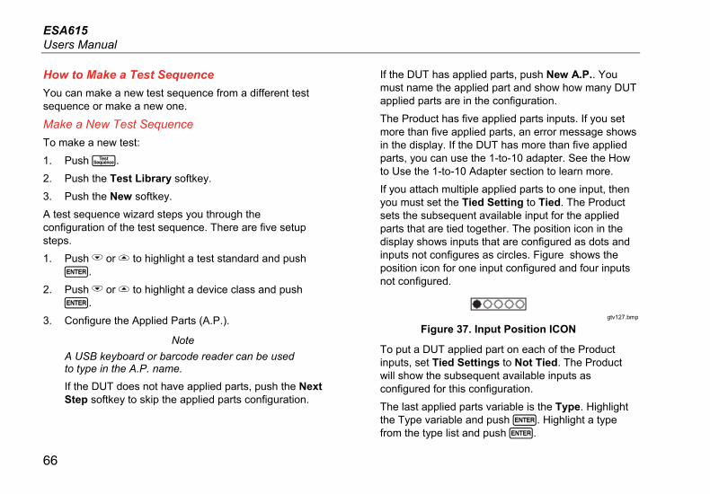
ESA615 Users Manual
66
How to Make a Test Sequence
You can make a new test sequence from a different test sequence or make a new one.
Make a New Test Sequence
To make a new test:
1. Push .
2. Push the Test Library softkey.
3. Push the New softkey.
A test sequence wizard steps you through the configuration of the test sequence. There are five setup steps.
1. Push or to highlight a test standard and push .
2. Push or to highlight a device class and push .
3. Configure the Applied Parts (A.P.).
Note
A USB keyboard or barcode reader can be used to type in the A.P. name.
If the DUT does not have applied parts, push the Next Step softkey to skip the applied parts configuration.
If the DUT has applied parts, push New A.P.. You must name the applied part and show how many DUT applied parts are in the configuration.
The Product has five applied parts inputs. If you set more than five applied parts, an error message shows in the display. If the DUT has more than five applied parts, you can use the 1-to-10 adapter. See the How to Use the 1-to-10 Adapter section to learn more.
If you attach multiple applied parts to one input, then you must set the Tied Setting to Tied. The Product sets the subsequent available input for the applied parts that are tied together. The position icon in the display shows inputs that are configured as dots and inputs not configures as circles. Figure shows the position icon for one input configured and four inputs not configured.
gtv127.bmp
Figure 37. Input Position ICON
To put a DUT applied part on each of the Product inputs, set Tied Settings to Not Tied. The Product will show the subsequent available inputs as configured for this configuration.
The last applied parts variable is the Type. Highlight the Type variable and push . Highlight a type from the type list and push .

Electrical Safety Analyzer Test Sequences
67
Push the Done softkey to complete the applied part configuration.
To edit an applied part configuration, use or to highlight the A.P. configuration and push .
4. Edit test settings.
Table 7 is a list of test settings with their descriptions and default values.
To set one of the test setting, push or to highlight a test setting and push . After you change the setting, push the Done softkey.
5. Name the test sequence. When you push the Next Step softkey in the edit test settings step, the Product automatically names the sequence Test Sequence followed by the date and time. To accept the default name, push the Next Step softkey. To change the name, push the Edit softkey.
Note
A USB keyboard or barcode reader can be used to edit the test sequence name.
The test sequence is complete. To put the test sequence on the memory card, push the Save softkey. To see the test sequence parameters before you save it, push the Edit softkey.

ESA615 Users Manual
68
Table 7. Test Settings for Test Sequences
Test Setting Description Default Value
Pause after power on If set to yes, delays the start of the test by the time set in the Power on delay parameter when power is applied to the DUT.
No
Pause before power off If set to yes, delays the start of the test by the time set in the Power off delay parameter when power is removed from the DUT.
No
Power on delay The time the Product will wait before it does the subsequent step after power is applied to the DUT. The range is 0 to 9999 seconds.
2 sec
Power off delay The time the Product will wait before it does the subsequent step after power is removed from the DUT. The range is 0 to 9999 seconds.
0 sec
Test Speed [1] When set to Normal, the Product does a leakage current measurement in 5 seconds and an insulation resistance test in 1 minute.
When set to Rapid, the Product measures leakage current as fast as possible and an insulation resistance test in 3 seconds.
Normal
Test Mode When set to Automatic, the Product does each test sequence step automatically. When set to Step-by-Step, you must push the Next Step softkey to move to the subsequent step in the sequence.
Automatic
Halt on Test Failure When set to Yes, the Product stops the test sequence when a fault is sensed. Yes

Electrical Safety Analyzer Test Sequences
69
Table 7. Test Settings for Test Sequences (cont.)
Test Setting Description Default Value
Multiple PE Tests If set to Yes, the Product prompts you to repeat PE tests or continue. No
Multiple Non-Earth Leakage
If set to Yes, the Product prompts you to repeat non-earth leakage tests or continue.
No
Patient Lead Records storage [2]
When set to Store all, all results are put into the test results. If set to Store worst/last, only the worst measured value is put into the test results. If set to store worst/last and all measured values are the same, then the last value is put into the test results.
Store worst/last
Insulation Test Voltage Sets the insulation test voltage to 250 V dc or 500 V dc. 500 V dc
Reverse Polarity If set to No, reverse polarity tests will be skipped. Yes
[1] You can change the test speed parameter on a test sequence to decrease the time necessary to do a test sequence.
[2] Applies to leakage current and multiple PE tests only.

ESA615 Users Manual
70
Make a Test Sequence from a Test Sequence in the Test Library
To make a test sequence from a test sequence already in the test library:
1. Push .
2. Push the Test Library softkey.
3. Push or to highlight a test sequence name.
Note
Push softkey F1 to toggle between an A to Z or Z to A sort of the test sequences.
4. Push the View/Edit softkey.
5. Push the Save as New softkey.
6. Type in a new name with the screen keyboard.
Note
A USB keyboard or barcode reader can be used to edit the test sequence name.
7. Push the Done softkey.
The new test sequence steps are filled in with the steps from the initial test sequence.
8. Push the Edit softkey.
Go through each setup step of the test sequence and accept the parameters or change them for the new test sequence.
9. Push the Save softkey to save the test sequence and exit the wizard.
Edit a Test Sequence
To change one or more steps of a test sequence:
1. Push .
2. Push the Test Library softkey.
3. Push or to highlight a test sequence name.
Note
Push softkey F1 to toggle between an A to Z or Z to A sort of the test sequences.
4. Push the View/Edit softkey.
5. Push the Edit softkey.
You go through each step of the test sequence and accept the step parameters or change them.

Electrical Safety Analyzer Test Sequences
71
Do a Test Sequence
To do a test sequence:
1. Push to show the test sequence screen in Figure 38.
gtv125.bmp
Figure 38. Test Sequence Screen
2. Push the Test Library softkey.
3. Push or to highlight a test sequence name.
Note
Push softkey F1 to toggle between an A to Z, Z to A, by date sort of the test sequences.
4. Push .
Note
To see the details of the test sequence you are about to start, push the Sequence Details softkey.
5. Push the Next softkey.
The equipment information screen in Figure 39 shows in the display.
gtv126.bmp
Figure 39. Equipment Information Screen
The number, serial number, manufacturer, model, and location of the Device Under Test can be typed in to help identify the DUT on the test results.

ESA615 Users Manual
72
Note
A USB keyboard or barcode reader can be used to type in the DUT information. You can use a barcode reader to automatically move through each field if it automatically sends a carriage return.
When the test sequence step is a visual inspection, you must push the Pass, Fail, or N/A softkey to move on to the subsequent test step.
When the Product measures a value(s) for a test, Testing shows in the display. When the test step is done, the results are shown with PASS or FAIL in the display.
To add comments when a test step ends, push the Add Comments softkey. When you see individual results of a Test Summary, you can push the Add Comments softkey to type in more information about the test step.
When the test sequence is done, a name is made from the equipment number, the date, and the time. To change the name, push or the Edit softkey. To put the test sequence on the memory card, push the Save softkey.
Show Test Results
To show test results in the display:
1. Push .
2. Push or to highlight a test results name.
Note
Push softkey F1 to toggle between sort results by date or sort A-Z.
3. Push to show the test and its results in the display.
4. Push or to highlight a test result.
5. Push to show the test results in the display.
6. Push the Back softkey to go back to the test results list.
Note
A USB keyboard or barcode reader can be used to edit the test results name.
When you push the Start Test Sequence softkey, the complete test sequence starts.
Electrical Safety Analyzer Maintenance
73
Delete a Set of Test Results
To delete a test result:
1. Push .
2. Push or to highlight a test result name.
Note
Push softkey F1 to toggle between sort results by date or sort A-Z.
3. Push the Delete softkey.
A delete confirmation screen will show in the display.
4. Push the Delete softkey.
Maintenance
Warning
To prevent possible electrical shock, fire, or personal injury:
• Have an approved technician repair the Product.
• Use only specified replacement fuses.
• Use only specified replacement parts.
• Remove the input signals before you clean the Product.
• Disconnect the mains power cord before you remove the Product covers.
• Turn off the Product and remove the mains power cord. Stop for two minutes to let the power assemblies discharge before you open the fuse door.
• Do not operate the Product with covers removed or the case open. Hazardous voltage exposure is possible.
The Product is a calibrated measurement instrument. Use the necessary precautions to prevent mechanical abuse that could change the calibrated adjustments.
Fuse Test and Fuse Replacement
Warning
To prevent electric shock, remove all power cords and test leads from the Product before you open the fuse door.
For electrical protection of the equipment outlet, the Product uses two fuses, one in the live (L1) line and one in the neutral (L2) line. To do a fuse test:
1. Turn the Product so the case bottom is up. See Figure .
2. Flip up the tilt stand.
3. Remove the screw in the fuse door with a #2 Phillips head screwdriver and lift the fuse door from the Product.
4. Remove the two fuses from the Product.

ESA615 Users Manual
74
F1 - F2
gtv111.eps
Figure 40. Fuse Access
5. Use a multimeter to measure the continuity of each fuse.
If a fuse does not show continuity, replace the fuse(s) with a fuse of the same current and voltage rating. Applicable fuse ratings are posted on the case bottom label of the Product. Table is a list of available fuses with Fluke Biomedical part numbers.
6. Reinstall the fuse door and secure it with the screw.
How to Clean the Product
Warning
To prevent electric shock, do not clean the Product plugged into mains or attached to a DUT.
Caution
Do not pour fluid onto the Product surface. Fluid in the electrical circuitry can cause the Product to fail.
Caution
Do not use spray cleaners on the Product. This can cause fluid to leak into the Product and damage electronic components.
Clean the Product occasionally with a damp cloth and weak detergent. Try to prevent the entrance of liquids.
Clean the adapter cables with the same precautions. Examine them for damage and deterioration of the insulation. Examine the connections for integrity before each use.

Electrical Safety Analyzer Replaceable Parts
75
Replaceable Parts Table is a list of replaceable parts for the Product.
Table 8. Replaceable Parts
Item Fluke Biomedical Part Number
ESA615 Getting Started Manual 4105845
ESA615 Users Manual CD 4105850
Power Cord
USA/Japan 2238680
UK 2238596
Australia/China 2238603
Europe 2238615
France/Belgium 2238615
Thailand 2238644
Israel 2434122
Switzerland 3379149
Brazil 3841358
USA to Brazil Outlet Adapter 4151242
Null Post Adapter 3326842
Ansur, CD with demo version 2795488

ESA615 Users Manual
76
Table 8. Replaceable Parts (cont.)
Item Fluke Biomedical Part Number
5-to-5 Banana jack to ECG (BJ2ECG) adapter 3359538
Carrying Case 2248650
Data Transfer Cable 4034393
Fuse
USA-115, Japan T20A 250V Fuse (Time Lag), 1¼ in x ¼ in 2183691
Australia, China, Switzerland
T10A 250V Fuse (Time Lag), 1¼ in x ¼ in 109298
Europe, UK, USA-220, France/Belgium, Thailand, Brazil, Israel
T16A 250V Fuse (Time Lag), 6.3 mm x 32 mm 3321245
15 – 20 A Adapter 2195732
ESA USA/AUS/ISR Accessory Kit:
Test Lead Set TP1 Test Probe Set AC285 Alligator Clip Set
3111008
ESA EUR Accessory Kit:
Test Lead Set TP74 Test Probe Set AC285 Alligator Clip Set
3111024
To ensure safety, use exact replacement only.

Electrical Safety Analyzer Accessories
77
Accessories Table is a list of available accessories for the Product.
Table 9. Accessories
Item Fluke Biomedical Part Number
Test Leads with Retractable Sheath 1903307
Ground Pin Adapters 2242165
1–to–10 ECG Adapter 3392119
Universal Snap to Banana Adapter 2462072
Ultrasound Test Cable Adapter 3472633
USB Wireless Dongle 3341333

ESA615 Users Manual
78
Specifications Temperature
Operating ............................................................ 10 °C to 40 °C (50 °F to 104 °F)
Storage ............................................................... -20 °C to 60 °C (-4 °F to 140 °F)
Humidity ................................................................. 10 % to 90 % non-condensing
Altitude
100 V/115 V ac mains supply voltage ................. 5000 m
230 V ac mains supply voltage ........................... 2000 m
Display ................................................................... LCD display
Communications
USB Device Upstream Port ................................ Mini-B connector for control by a computer
USB Host Controller Port .................................... Type A, 5 V output, 0.5 A max load. Connector for keyboard and barcode reader
Wireless .............................................................. IEEE 802.15.4 for control by a computer
Modes of Operation .............................................. Manual and remote
Power
100 V/115 V power outlet .................................... 90 to 132 V ac rms, 47 to 63 Hz, 20 A maximum
230 V power outlet .............................................. 180 to 264 V ac rms, 47 to 63 Hz, 16 A maximum
Weight .................................................................... 1.6 kg (3.5 lb)
Size ......................................................................... 28.5 cm x 17.6 cm x 8.4 cm (11.2 in x 6.9 in x 3.3 in)
Safety Standards
CE ....................................................................... IEC/EN61010-1 3rd Edition; Pollution degree 2, CAT II
CSA ..................................................................... CAN/CSA-C22.2 No 61010-1; UL61010-1
Electromagnetic Compatibility Standards (EMC)
European EMC ................................................... EN61326-1
IP Rating ................................................................ 20

Electrical Safety Analyzer Detailed Specifications
79
Detailed Specifications Test Standard Selections ........................................ ANSI/AAMI ES-1, IEC62353, IEC60601-1, and AN/NZS 3551
Voltage
Ranges (Mains voltage) ...................................... 90.0 V to 132.0 V ac rms 180.0 V to 264.0 V ac rms
Range (Point-to-point voltage)
5000 m ............................................................ 0.0 V to ≤150 V ac rms
2000 m ............................................................ 0.0 V to ≤300.0 V ac rms
Accuracy.............................................................. ±(2 % of reading + 0.2 V)
Earth Resistance
Modes.................................................................. 2-Wire
Test Current ........................................................ >200 mA ac
Range .................................................................. 0.000 Ω to 2.000 Ω
Accuracy.............................................................. ±(2 % of reading + 0.015 Ω)
Equipment Current
Range .................................................................. 0.0 A to 20.0 A ac rms
Accuracy.............................................................. ±(5 % of reading + (2 counts or 0.2 A, whichever is greater))
Duty cycle ............................................................ 15 A to 20 A, 5 min on/5 min off 10 A to 15 A, 7 min on/3 min off 0 A to 10 A, continuous
Leakage Current
Modes* ................................................................ AC+DC (True-rms) AC only DC only * For tests that do not use MAP voltage, AC+DC, AC ONLY, and DC ONLY modes are available for all leakages. MAP voltages are available only in True-rms (shown as AC+DC)

ESA615 Users Manual
80
Patient Load Selection ........................................ AAMI ES1-1993 Fig. 1 IEC 60601: Fig. 15
Crest factor ......................................................... ≤3
Ranges ................................................................ 0.0 μA to 199.9 μA 200 μA to 1999 μA 2.00 mA to 10.00 mA
Accuracy
DC to 1 kHz ..................................................... ±(1 % of reading + (1 μA or 1 LSD, whichever is greater))
1 kHz to 100 kHz ............................................. ±(2 % of reading + (1 μA or 1 LSD, whichever is greater))
1 kHz to 5 kHz (current > 1.6 mA) .................. ±(4 % of reading + (1 μA or 1 LSD, whichever is greater))
100 kHz to 1 MHz ........................................... ±(5 % of reading + (1 μA or 1 LSD, whichever is greater))
Note
Accuracy for Isolation, MAP, Direct AP, Alternative AP, and Alternative Equipment leakage tests all ranges are:
• At 120 V ac + (2.5 μA or 1 LSD, whichever is greater)
• At 230 V ac additional ± 3.0 % and + (2.5 μA or 1 LSD, whichever is greater)
For Alternative equipment, Alternative AP, and Direct AP leakage tests, the leakage values are compensated for nominal mains as per 62353. Therefore, the accuracy specified for other leakages is not applicable.
Mains on applied part test voltage ...................... 100 % ±7 % of Mains for AAMI, current limited to 1 mA ±25 % per AAMI 100 % ±7 % of Mains for IEC 62353 current limited to 3.5 mA ±25 % per IEC 62353 100 % ±7 % of Mains for IEC 60601-1 current limited to 7.5 mA ±25 % per IEC 60601-1
Differential leakage
Ranges ................................................................ 75 μA to 199 μA 200 μA to 1999 μA 2.00 mA to 20.00 mA
Accuracy ............................................................. ±(10 % of reading + (2 counts or 20 μA, whichever is greater))
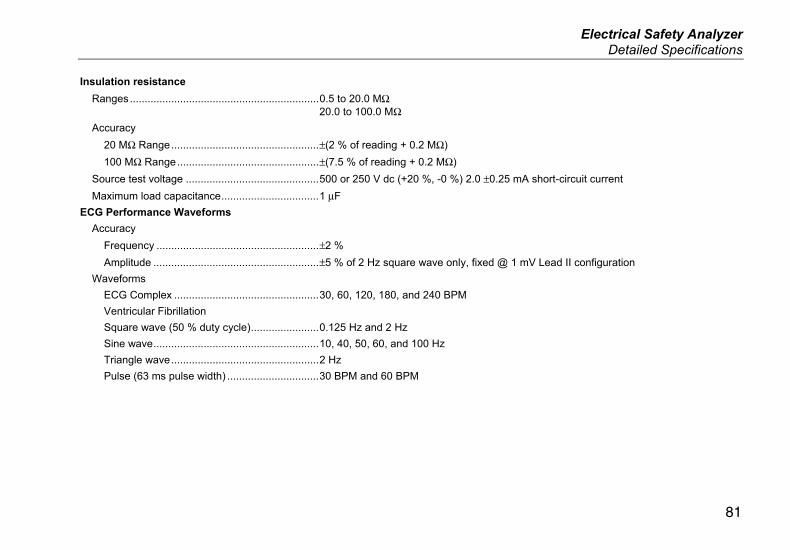
Electrical Safety Analyzer Detailed Specifications
81
Insulation resistance
Ranges ................................................................ 0.5 to 20.0 MΩ 20.0 to 100.0 MΩ
Accuracy
20 MΩ Range .................................................. ±(2 % of reading + 0.2 MΩ)
100 MΩ Range ................................................ ±(7.5 % of reading + 0.2 MΩ)
Source test voltage ............................................. 500 or 250 V dc (+20 %, -0 %) 2.0 ±0.25 mA short-circuit current
Maximum load capacitance ................................. 1 μF
ECG Performance Waveforms
Accuracy
Frequency ....................................................... ±2 %
Amplitude ........................................................ ±5 % of 2 Hz square wave only, fixed @ 1 mV Lead II configuration
Waveforms
ECG Complex ................................................. 30, 60, 120, 180, and 240 BPM
Ventricular Fibrillation
Square wave (50 % duty cycle) ....................... 0.125 Hz and 2 Hz
Sine wave ........................................................ 10, 40, 50, 60, and 100 Hz
Triangle wave .................................................. 2 Hz
Pulse (63 ms pulse width) ............................... 30 BPM and 60 BPM

ESA615 Users Manual
82
Factory-Supplied Test Sequences
60601 3rd Edition Patient Monitor
60601 3rd Edition Defibrillator
60601 3rd Edition Infusion Pump
60601 3rd Edition Ultrasound Device
60601 3rd Edition Generic Device
60601 3rd Edition System
62353-Alt. Patient Monitor
62353-Alt. Defibrillator
62353-Alt. Infusion Pump
62353-Alt. Ultrasound Device
62353-Alt Generic Device
NFPA99 Patient Monitor
NFPA99 Defibrillator
NFPA99 Infusion Pump
NFPA99 Ultrasound Device
NFPA99 Generic Device
ANSI/AAMI ES-1 Patient Monitor
ANSI/AAMI ES-1 Defibrillator
ANSI/AAMI ES-1 Infusion Pump
ANSI/AAMI ES-1 Ultrasound Device
ANSI/AAMI ES-1 Generic Device


