Electrical Safety Analyzer - Flukeassets.fluke.com/manuals/esa620__umeng0300.pdf · Warranty and...
76
ESA620 Electrical Safety Analyzer Users Manual FBC-0028 January 2008, Rev. 3, 5/15 © 2008-2015 Fluke Corporation. All rights reserved. Specifications are subject to change without notice. All product names are trademarks of their respective companies.
Transcript of Electrical Safety Analyzer - Flukeassets.fluke.com/manuals/esa620__umeng0300.pdf · Warranty and...

ESA620 Electrical Safety Analyzer
Users Manual
FBC-0028 January 2008, Rev. 3, 5/15 © 2008-2015 Fluke Corporation. All rights reserved. Specifications are subject to change without notice. All product names are trademarks of their respective companies.

Warranty and Product Support Fluke Biomedical warrants this instrument against defects in materials and workmanship for one year from the date of original purchase OR two years if at the end of your first year you send the instrument to a Fluke Biomedical service center for calibration. You will be charged our customary fee for such calibration. During the warranty period, we will repair or at our option replace, at no charge, a product that proves to be defective, provided you return the product, shipping prepaid, to Fluke Biomedical. This warranty covers the original purchaser only and is not transferable. The warranty does not apply if the product has been damaged by accident or misuse or has been serviced or modified by anyone other than an authorized Fluke Biomedical service facility. NO OTHER WARRANTIES, SUCH AS FITNESS FOR A PARTICULAR PURPOSE, ARE EXPRESSED OR IMPLIED. FLUKE SHALL NOT BE LIABLE FOR ANY SPECIAL, INDIRECT, INCIDENTAL OR CONSEQUENTIAL DAMAGES OR LOSSES, INCLUDING LOSS OF DATA, ARISING FROM ANY CAUSE OR THEORY.
This warranty covers only serialized products and their accessory items that bear a distinct serial number tag. Recalibration of instruments is not covered under the warranty.
This warranty gives you specific legal rights and you may also have other rights that vary in different jurisdictions. Since some jurisdictions do not allow the exclusion or limitation of an implied warranty or of incidental or consequential damages, this limitation of liability may not apply to you. If any provision of this warranty is held invalid or unenforceable by a court or other decision-maker of competent jurisdiction, such holding will not affect the validity or enforceability of any other provision.
7/07

Notices
All Rights Reserved Copyright 2008-2015, Fluke Biomedical. No part of this publication may be reproduced, transmitted, transcribed, stored in a retrieval system, or translated into any language without the written permission of Fluke Biomedical.
Copyright Release Fluke Biomedical agrees to a limited copyright release that allows you to reproduce manuals and other printed materials for use in service training programs and other technical publications. If you would like other reproductions or distributions, submit a written request to Fluke Biomedical.
Unpacking and Inspection Follow standard receiving practices upon receipt of the instrument. Check the shipping carton for damage. If damage is found, stop unpacking the instrument. Notify the carrier and ask for an agent to be present while the instrument is unpacked. There are no special unpacking instructions, but be careful not to damage the instrument when unpacking it. Inspect the instrument for physical damage such as bent or broken parts, dents, or scratches.
Technical Support For application support or answers to technical questions, either email [email protected] or call 1-800- 850-4608 or 1-440-248-9300. In Europe, email [email protected] or call +31-40-2675314.
Claims Our routine method of shipment is via common carrier, FOB origin. Upon delivery, if physical damage is found, retain all packing materials in their original condition and contact the carrier immediately to file a claim. If the instrument is delivered in good physical condition but does not operate within specifications, or if there are any other problems not caused by shipping damage, please contact Fluke Biomedical or your local sales representative.

Returns and Repairs Return Procedure
All items being returned (including all warranty-claim shipments) must be sent freight-prepaid to our factory location. When you return an instrument to Fluke Biomedical, we recommend using United Parcel Service, Federal Express, or Air Parcel Post. We also recommend that you insure your shipment for its actual replacement cost. Fluke Biomedical will not be responsible for lost shipments or instruments that are received in damaged condition due to improper packaging or handling. Use the original carton and packaging material for shipment. If they are not available, we recommend the following guide for repackaging:
Use a double–walled carton of sufficient strength for the weight being shipped. Use heavy paper or cardboard to protect all instrument surfaces. Use nonabrasive material around all projecting parts. Use at least four inches of tightly packed, industry-approved, shock-absorbent material around the instrument.
Returns for partial refund/credit: Every product returned for refund/credit must be accompanied by a Return Material Authorization (RMA) number, obtained from our Order Entry Group at 1-440-498-2560.
Repair and calibration: To find the nearest service center, go to www.flukebiomedical.com/service or In the U.S.A.: Cleveland Calibration Lab Tel: 1-800-850-4608 x2564 Email: [email protected] Everett Calibration Lab Tel: 1-888-99 FLUKE (1-888-993-5853) Email: [email protected]
In Europe, Middle East, and Africa: Eindhoven Calibration Lab Tel: +31-40-2675300 Email: [email protected] In Asia: Everett Calibration Lab Tel: +425-446-6945 Email: [email protected]
To ensure the accuracy of the Product is maintained at a high level, Fluke Biomedical recommends the product be calibrated at least once every 12 months. Calibration must be done by qualified personnel. Contact your local Fluke Biomedical representative for calibration.

Certification This instrument was thoroughly tested and inspected. It was found to meet Fluke Biomedical’s manufacturing specifications when it was shipped from the factory. Calibration measurements are traceable to the National Institute of Standards and Technology (NIST). Devices for which there are no NIST calibration standards are measured against in-house performance standards using accepted test procedures.
WARNING Unauthorized user modifications or application beyond the published specifications may result in electrical shock hazards or improper operation. Fluke Biomedical will not be responsible for any injuries sustained due to unauthorized equipment modifications.
Restrictions and Liabilities Information in this document is subject to change and does not represent a commitment by Fluke Biomedical. Changes made to the information in this document will be incorporated in new editions of the publication. No responsibility is assumed by Fluke Biomedical for the use or reliability of software or equipment that is not supplied by Fluke Biomedical, or by its affiliated dealers.
Manufacturing Location The ESA620 Electrical Safety Analyzer is manufactured at Fluke Biomedical, 6920 Seaway Blvd., Everett, WA, U.S.A.

Table of Contents
Title Page
Introduction .................................................................................................................... 1 Safety Information .......................................................................................................... 3 Intended Use .................................................................................................................. 4 Unpacking the Analyzer ................................................................................................. 5 Instrument Familiarization .............................................................................................. 6 Connecting to Line Power .............................................................................................. 10 Connecting a DUT to the Analyzer ................................................................................. 10 Turning the Analyzer On ................................................................................................ 10 Accessing the Analyzer’s Functions ............................................................................... 12 Setting Up the Analyzer .................................................................................................. 12
Setting the GFCI Limit ............................................................................................... 13 Selecting 2-Wire or 4-Wire Measurements ................................................................ 14 Setting the Default Measurement Current ................................................................. 14 Setting Polarity Switching Delay ................................................................................ 17 Setting the Display Contrast ...................................................................................... 17
i

ESA620 Users Manual
Setting up the Beeper ............................................................................................... 17 Performing Electrical Safety Tests ................................................................................. 18
Setting the Test Standard ......................................................................................... 18 Performing an Accessible Voltage Test (IEC 61010 only) ........................................ 18 Performing Mains Voltage Testing ............................................................................ 19 Performing a Protective Earth Resistance Test ........................................................ 19 Performing an Insulation Resistance Test ................................................................ 24 Performing a Current Consumption Test .................................................................. 30 Performing Leakage Current Tests ........................................................................... 30
Measuring Earth Leakage Current ....................................................................... 31 Performing an Enclosure Leakage Test ............................................................... 33 Performing a Patient Leakage Test ...................................................................... 35 Performing Patient Auxiliary Leakage Tests ......................................................... 37
Performing a Mains on Applied Part Leakage Test ................................................... 39 Performing an Alternative Equipment Leakage Test ................................................. 41 Performing an Alternative Applied Part Leakage Test .............................................. 41 Performing a Direct Equipment Leakage Test .......................................................... 44 Performing a Direct Applied Part Leakage Test ........................................................ 46 Performing a Differential Leakage Current Test ........................................................ 48 Performing an Accessible Leakage Current Test (IEC 61010 only) .......................... 48
Making Point-To-Point Measurements ........................................................................... 50 Measuring Voltage .................................................................................................... 50 Measuring Resistance .............................................................................................. 50 Measuring Current .................................................................................................... 51
Simulating ECG Waveforms .......................................................................................... 51 Controlling the Analyzer Remotely................................................................................. 53 Maintenance .................................................................................................................. 53 Cleaning the Analyzer .................................................................................................... 54 Replaceable Parts ......................................................................................................... 55
ii

Contents (continued)
Accessories .................................................................................................................... 57 Specifications ................................................................................................................. 58 Detailed Specifications ................................................................................................... 59
iii

ESA620 Users Manual
iv

List of Tables
Table Title Page
1. Symbols ................................................................................................................................. 2 2. Top-Panel Controls and Connections .................................................................................... 7 3. Rear-Panel Connections ....................................................................................................... 9 4. Schematic Abbreviations ....................................................................................................... 22 5. Test Names Based on Selected Standard ............................................................................. 30 6. Replaceable Parts ................................................................................................................. 55 7. Accessories ........................................................................................................................... 57
v

ESA620 Users Manual
vi

List of Figures
Figure Title Page
1. Top-Panel Controls and Connections .................................................................................... 6 2. Rear-Panel Connections ....................................................................................................... 8 3. Analyzer Ready for Operation ............................................................................................... 10 4. DUT Connections to the Analyzer ......................................................................................... 11 5. Leakage Current Menu .......................................................................................................... 12 6. Setup Menu ........................................................................................................................... 13 7. 2-Wire Earth Resistance Measurement Connections ............................................................ 15 8. 4-Wire Earth Resistance Measurement Connection .............................................................. 16 9. Mains Voltage Test Menu ...................................................................................................... 19 10. DUT Ground Resistance Measurement................................................................................. 21 11. Protective-Earth Resistance Measurement Schematic ......................................................... 23 12. Insulation Resistance Measurement ..................................................................................... 24 13. Mains to Protective-Earth Insulation Resistance Test Schematic .......................................... 25 14. Applied Parts to Protective-Earth Insulation Test Schematic ................................................. 26 15. Mains to Applied Parts Insulation Test Schematic ................................................................. 27
vii

ESA620 Users Manual
16. Mains to Non-Earth Accessible Conductive Points Schematic ............................................. 28 17. Applied Parts to Non-Earth Conductive Points Schematic .................................................... 29 18. Leakage Current Main Menu ................................................................................................ 31 19. Earth Leakage Current Test Schematic ................................................................................ 32 20. Enclosure Leakage Current Test Schematic ......................................................................... 34 21. Patient Leakage Current Test Schematic ............................................................................. 36 22. Applied Parts Connection Posts Display ............................................................................... 37 23. Patient Auxiliary Leakage Current Test Schematic ............................................................... 38 24. Mains-On-Applied-Parts-Leakage-Current Test Schematic .................................................. 40 25. Alternative Equipment Leakage Current Test Schematic ...................................................... 42 26. Alternative Applied Part Leakage Test Schematic ................................................................ 43 27. Direct Equipment Leakage Test Schematic .......................................................................... 45 28. Direct Applied Parts Leakage Current Test Schematic ......................................................... 47 29. Differential Leakage Current Test Schematic ....................................................................... 49 30. Point-To-Point Function Menu .............................................................................................. 50 31. ECG Waveform Simulation Menu ......................................................................................... 51 32. ECG Monitor Connections .................................................................................................... 52
viii

Electrical Safety Analyzer
Introduction The Fluke Biomedical ESA620 Electrical Safety Analyzer (hereafter the Analyzer) is a full-featured, compact, portable analyzer, designed to verify the electrical safety of medical devices. The Analyzer tests to international (IEC 60601-1, EN62353, AN/NZS 3551, IEC61010, VDE 751) and domestic (ANSI/AAMI ES1, NFPA 99) electrical-safety standards. The integrated ANSI/AAMI ES1, IEC60601-1, and IEC61010 patient loads are easily selectable.
The Analyzer performs the following tests:
• Mains (Line) voltage • Protective Earth (or Ground Wire) Resistance • Equipment current • Insulation resistance
• Earth (Ground) leakage • Enclosure (Chassis) leakage • Patient (Lead to Ground) and patient auxiliary
(Lead to Lead) leakage • Mains on applied parts leakage (Lead isolation) • Differential leakage • Direct equipment leakage • Direct applied part leakage • Alternative equipment leakage • Alternative applied part patient leakage • Accessible part leakage • Accessible part voltage • Point to point leakage, voltage, and resistance • ECG simulation and performance waveforms
1

ESA620 Users Manual
Table 1. Symbols
Symbol Description
WARNING.RISK OF DANGER.
WARNING. HAZARDOUS VOLTAGE. Risk of electric shock.
Certified by CSA Group to North American safety standards.
Conforms to relevant Australian EMC standards.
Conforms to European Union directives
Conforms to relevant South Korean EMC Standards.
This product complies with the WEEE Directive marking requirements. The affixed label indicates that you must not discard this electrical/electronic product in domestic household waste. Product Category: With reference to the equipment types in the WEEE Directive Annex I, this product is classed as category 9 "Monitoring and Control Instrumentation" product. Do not dispose of this product as unsorted municipal waste.
Measurement Category II is applicable to test and measuring circuits connected directly to utilization points (socket outlets and similar points) of the low-voltage MAINS installation.
Equipotential
2

Electrical Safety Analyzer Safety Information
Safety Information In this manual, a Warning identifies conditions and procedures that are dangerous to the user. A Caution identifies conditions and procedures that can cause damage to the Product or the equipment under test.
Warning To prevent possible electrical shock or personal injury:
• Use this Analyzer only in the manner specified by the manufacturer or the protection provided may be impaired.
• Read the Users Manual before operating the Analyzer.
• Do not connect the Analyzer to a patient or equipment connected to a patient. The Analyzer is intended for equipment evaluation only and should never be used in diagnostics, treatment or in any other capacity where the Analyzer would come in contact with a patient.
• Do not use the product in wet locations, around explosive gases or dust.
• Inspect the Analyzer before using it. Do not use the Analyzer if abnormal conditions of any sort are noted (such as a faulty display, broken case, etc.)
• Inspect the test leads for damaged insulation or exposed metal. Check test lead continuity. Replace damaged leads before using the Analyzer.
• When testing, always be sure to keep your fingers behind the safety barriers on the test leads.
• Never open the Analyzer's case. Dangerous voltages are present. There are no user replaceable parts in the Analyzer.
• Have the Analyzer serviced only by qualified personnel.
• Do not use the 15-20A adapter to power devices rated in excess of 15A. Doing so may overload the installation.
3

ESA620 Users Manual
• The Analyzer must be properly earthed. Only use a supply socket that has a protective earth contact. If there is any doubt as to the effectiveness of the supply socket earth, do not connect the Analyzer. Do not use a two-conductor adapter or extension cord; this will break the protective ground connection.
• Use extreme caution when working with voltages above 30 volts.
• Use the proper terminals, functions and ranges for the test being performed.
• Do not touch metal parts of the device under test (DUT) during analysis. The DUT should be considered an electrical shock hazard when connected to the Analyzer as some tests involve high voltages, high currents, and/or the removal of DUT earth bond.
Intended Use The Analyzer is intended for use by trained service technicians to perform periodic inspections on a wide range of medical equipment. The testing procedures are menu-driven, and simple to operate.
The Product is an electronic signal source and measurement device for verifying the electrical safety of medical devices. The Product also provides ECG simulation and performance waveforms to verify patient monitors are performing within their operating specifications.
The Product provides the following function categories:
• ECG Functions • ECG-Performance Testing
The intended user is a trained biomedical equipment technician who performs periodic preventative maintenance checks on patient monitors in service. Users can be associated with hospitals, clinics, original equipment manufacturers and independent service companies that repair and service medical equipment.
The end user is an individual, trained in medical instrumentation technology. This Product is intended to be used in the laboratory environment, outside of the patient care area, and is not intended for use on patients, or to test devices while connected to patients. This Product is not intended to be used to calibrate medical equipment. It is intended for over the counter use.
4

Electrical Safety Analyzer Unpacking the Analyzer
Unpacking the Analyzer Carefully unpack all items from the box and check that you have the following items:
• ESA620 • Getting Started Manual • Users Manual CD • Carrying case • Power cord • 15 – 20 A Adapter (USA only) • Test lead set • TP1 Test probe set (USA, Australia, and Israel
only) • TP74 Test probe set (Europe only) • Ansur demo CD • Alligator clip set • Null post adapter • Data transfer cable
5
ESA620 Users Manual
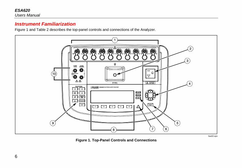
Instrument Familiarization Figure 1 and Table 2 describes the top-panel controls and connections of the Analyzer.
faw02.eps
Figure 1. Top-Panel Controls and Connections
6

Electrical Safety Analyzer Instrument Familiarization
Table 2. Top-Panel Controls and Connections
Item Name Description
1 ECG/Applied Parts Posts
Connection posts for Device Under Test (DUT) leads, like ECG leads. Used to test for leakage current through leads and to supply ECG signals and performance waveforms to a DUT.
2 Nulling Jack Connection for zeroing test lead resistance. Use the probe attached to the test lead to put into the null jack. Use the null post adapter when you use the alligator clip attached to the test lead.
3 Equipment Outlet Equipment outlet, specific to the version of the Analyzer, which provides a DUT connection.
4 Navigation Buttons Cursor control buttons for navigating menus and lists.
5 Test Button Initiates selected tests.
6 Equipment Outlet Configuration Buttons
Controls the wiring of the equipment outlet. Opens and closes the neutral and ground connection and reverses the polarity of the neutral and hot connection.
7 High Voltage Indicator
Indicates when high voltage is applied to the ECG/Applied Parts posts or L1 and L2 of the Test Receptacle.
8 Function Softkeys Keys F1 through F5 are used to select from a number of selections that appear in the LCD display above each function softkey.
9 Test Function Buttons
Selects the various Analyzer test functions.
10 Input Jacks Test lead connectors.
7

ESA620 Users Manual
Figure 2 and Table 3 describe the rear-panel connections of the Analyzer.
faw01.eps
Figure 2. Rear-Panel Connections
8

Electrical Safety Analyzer Instrument Familiarization
Table 3. Rear-Panel Connections
Item Name Description
1 AC Power Switch Turns ac power on and off
2 AC Power Input Connector A grounded male three-prong (IEC 320 C20) connector that accepts the line-power cord.
3 Line Power Fuse Holders The line power fuses.
4 USB Device Port (B-style connector)
Digital connection for controlling the Analyzer from a PC or instrument controller.
9

ESA620 Users Manual
Connecting to Line Power Warning
To avoid shock hazard and for proper Analyzer operation, connect the factory supplied three-conductor line power cord to a properly grounded power outlet. Do not use a two-conductor adapter or extension cord; this will break the protective ground connection.
Connect the Analyzer to a properly grounded three-prong outlet. The Analyzer will not properly test a DUT when the ground lead is open.
The Analyzer is intended for use with single-phase, grounded power. It is not intended for dual, split-phase or three-phase power configurations. But it can be used with any power system that supplies the correct voltages for single-phase and is grounded.
Connecting a DUT to the Analyzer A Device Under Test (DUT) can be connected in a number of different ways depending on the device and the number of connections needed for a full electrical safety test. Figure 4 shows a DUT connected to the test receptacle, applied parts posts, and a separate connection to the DUT’s enclosure or protected earth ground.
Turning the Analyzer On Note
To ensure the high voltage indicator is working, look for it to illuminate during the power-up self test.
Press the power switch on the back panel so the “I” side of the ac power switch is depressed. The Analyzer will perform a series of self tests and then display the message shown in Figure 3 when the self test has completed successfully.
faw05.eps
Figure 3. Analyzer Ready for Operation
10

Electrical Safety Analyzer Turning the Analyzer On
faw03.eps
Figure 4. DUT Connections to the Analyzer
11

ESA620 Users Manual
During the self-test, the Analyzer checks its ac mains input for proper polarity, ground integrity and voltage level. The high voltage indicator illuminates briefly during the self test. If the polarity is reversed, the Analyzer indicates this condition and allows the polarity to be reversed internally. If the ground is open, the Analyzer displays this fault. If the mains voltage is too high or too low, the Analyzer displays this fault and does not continue until the supply voltage is corrected and the ESA620 power cycled off and then on again.
Accessing the Analyzer’s Functions For each test and setup function, the Analyzer uses a series of menus to access various Analyzer test and setup variables. As shown in Figure 5, the Analyzer indicates various leakage current tests along the bottom of the display. An Exit selection is also indicated as a way of backing out of the leakage current tests. Pressing a softkey (F1 through F5) under a specific test will cause the analyzer to setup for or perform the selected test.
faw04.eps
Figure 5. Leakage Current Menu
In addition to the function softkeys, the Analyzer test functions may require using the navigation buttons to
select parameters as well. In the example above, the leakage selection has next to it. This icon indicates the selection is controlled by pressing or . In this example, the leakage current measurement is switched between AC+DC, AC only, or DC only. The applied parts indicator has on the left end and on the right end. These icons indicate the use of and to select an applied part.
The three buttons along the right side of the display () control the wiring of the Analyzer’s test receptacle for some electrical tests. The present state of these three buttons is displayed along the right edge of the display whenever these controls are active.
12

Electrical Safety Analyzer Setting Up the Analyzer
Setting Up the Analyzer There are a number of Analyzer parameters that are adjusted through a setup function. To access the Setup menu shown in Figure 6, press .
faw13.eps
Figure 6. Setup Menu
The setup parameters have been grouped into six categories: Instrument, Display, Sound, Instrument Info, Calibration, and Diagnostics.
Setting the GFCI Limit The GFCI (Ground Fault Current Interrupter) protects the DUT from short circuits when it is connected to the test receptacle of the Analyzer. (The GFCI has no effect during Insulation testing, Protective Earth Resistance testing, and Voltage testing because the test receptacle is not connected to mains power for these tests.) When the GFCI trips, it removes power from the test receptacle, and also the DUT, by opening the relays. The Analyzer continues to operate and shows “Fault Detected” with an explanation.
The Analyzer uses the GFCI setting for the standard the user selected for testing. For best results, verify the GFCI setting in the Setup menu. The AAMI standard specifies 5 mA. All of the other standards (for example IEC 60601-1 and IEC 62353) specify 10 mA. The 25 mA setting is a special case that is not defined in any standard.
To set the GFCI current limit:
1. From the Setup menu, press the softkey labeled Instrument, to show the instrument setup selections.
2. Press the softkey labeled More to show additional menu selections.
3. Press the softkey labeled GFCI Limit to open a scroll box above the softkey label.
4. Press or to adjust the current limit.
5. Press the softkey labeled GFCI Limit to exit the GFCI Limit setup function.
13

ESA620 Users Manual
Selecting 2-Wire or 4-Wire Measurements The 2-Wire and 4-Wire resistance measurement setting is under the Instrument setup functions. To switch between them:
1. Press the softkey labeled Instrument from the setup menu to reveal the instrument setup selections.
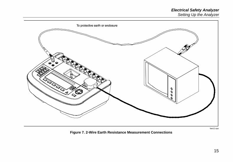
2. Press the softkey labeled Resistance to switch the type of resistance measurement between 2-Wire and 4-Wire method. See Figure 7 for 2-wire connections and Figure 8 for 4-wire connections.
Note Optional Kelvin Test Leads are available to make a 4-wire measurement with this Analyzer. See the Accessories section later in this manual.
3. Press the softkey Back then the softkey labeled Exit to exit the setup function.
Setting the Default Measurement Current The default test current selection for the Protective Earth (Ground Wire Resistance) Test can be set between 200 mA and 25 A ac. To change the default current:
1. Press the softkey labeled Instrument from the setup menu to reveal the instrument setup selections.
2. Press the softkey labeled Test Current to switch between 200 mA and 25 A ac.
3. Press the softkey Back then the softkey labeled Exit to exit the setup menu.
14
Electrical Safety Analyzer Setting Up the Analyzer
faw12.eps
Figure 7. 2-Wire Earth Resistance Measurement Connections
15

ESA620 Users Manual
faw11.eps
Figure 8. 4-Wire Earth Resistance Measurement Connection
16

Electrical Safety Analyzer Setting Up the Analyzer
Setting Polarity Switching Delay When switching the polarity of the Analyzer’s test receptacle, a delay can be set to control the actual switch time. To set the polarity delay:
1. Press the softkey labeled Instrument from the setup menu to reveal the instrument setup selections.
2. Press the softkey labeled Polarity Delay to open the scroll box above the softkey label.
3. Press or to adjust the delay from 0 to 5 seconds in 1 second steps.
4. Press the softkey Back then the softkey labeled Exit to exit the setup function.
Setting the Display Contrast There are two methods for setting the display contrast. From the “Select a Test….” menu or through the setup menu.
Whenever the Analyzer displays its start-up menu (Select a test…), pressing or will increase or decrease the display’s contrast respectively. Press the softkey labeled Done to exit contrast setup.
Another way to adjust the contrast is through the Analyzer’s setup menu.
1. Press the softkey labeled Display from the setup menu.
2. Press the softkey labeled Contrast. 3. Press or to increase or decrease the display’s
contrast respectively.
4. Press the softkey labeled Done to exit contrast setup.
Setting up the Beeper In addition to being enabled or disabled, the Analyzer’s beeper volume can be set as well. To setup the beeper:
1. Press the softkey labeled Sound from the setup menu.
2. Press the softkey labeled Beeper to switch the beeper on and off.
3. Press the softkey labeled Volume to open a scroll box above the softkey label.
4. Press or to increase or decrease the volume respectively.
5. Press the softkey labeled Done to go back to the setup menu.
17

ESA620 Users Manual
Performing Electrical Safety Tests The Analyzer is designed to perform a number of different electrical and performance tests on biomedical equipment. The following sections describe the various tests and how to perform them using the Analyzer.
Setting the Test Standard The Analyzer is designed to perform electrical safety testing based on a number of different safety standards. The IEC 60601 is the Analyzer’s default standard. To select another standard:
1. Press .
2. Press or to scroll through the standard selections.
3. When the desired standard is displayed, press the softkey labeled Select.
To exit the standard selection menu without changing the standards selection, press the softkey labeled Exit.
Some electrical tests may not be applicable for a specific standard. In these cases, the Analyzer’s menu will not display the excluded test as a selection.
Performing an Accessible Voltage Test (IEC 61010 only)
Note The Accessible Voltage test selection will only appear in the Analyzer’s menu when the standard is set to IEC61010.
The Accessible Voltage test measures the voltage that may exist between the DUT’s enclosure and protective earth. To access the Accessible Voltage test, press .
1. Connect the DUT’s power cord to the Analyzer’s test receptacle.
2. Connect a test lead from the Analyzer’s 2-WIRE V/Ω/A jack and an exposed metal part on the DUT’s enclosure. Any measured voltage is shown in the Analyzer’s display.
The following outlet conditions apply when performing this test:
• Normal polarity • Normal polarity, earth open • Normal polarity, neutral open • Reversed polarity • Reversed polarity, earth open • Reversed polarity, neutral open
18

Electrical Safety Analyzer Performing Electrical Safety Tests
Performing Mains Voltage Testing The Mains Voltage test measures the voltage on the mains input through three separate measurements. To access the Mains Voltage test, press . If the selected standard is IEC61010, then an additional step is required. Press the softkey labeled Mains Voltage. The Mains Voltage test menu is shown in Figure 9.
faw14.eps
Figure 9. Mains Voltage Test Menu
Press each function softkey to perform each of the three measurements: Live to neutral, neutral to earth, and live to earth.
Note Power to the test receptacle is off during the Mains Voltage test.
Performing a Protective Earth Resistance Test The Protective-Earth-Resistance test measures the impedance between the Analyzer’s test receptacle’s PE terminal and the exposed conductive parts of the DUT that are connected to the DUT’s Protective Earth.
Prior to conducting any leakage tests with the Analyzer, it is best to test the integrity of the ground connection between the Analyzer’s test receptacle ground and the DUT’s Protective earth ground or enclosure with this test.
To access the Protective Earth (Ground Wire Resistance) Test menu press .
Note The DUT is powered off for this test.
The Protective-Earth (Ground Wire) resistance measurement can be taken using either a 2-Wire or 4-Wire resistance measurement. To select between the two measurement methods, refer to the “Selecting 2-Wire or 4-Wire Measurements” section.
19

ESA620 Users Manual
To perform a protective-earth resistance test:
1. Ensure the power cord from the DUT is plugged into the Analyzer’s test receptacle.
2. Press to reveal the resistance function menu.
3. Connect one end of a test lead to the 2-WIRE V/Ω/A jack as shown in Figure 7. A low resistance reading is required to confirm a good ground connection through the power cord. Refer to the appropriate electrical safety standard for the specific limit value to be followed.
For the 4-Wire resistance measurement, skip steps 4 and 5.
4. Connect the other end of the test lead to the nulling jack in the middle of the top panel of the Analyzer.
Note Use the supplied null post adapter when you null the test lead with the alligator clip.
5. Press the softkey labeled Zero Leads. The Analyzer zeroes out the measurement to cancel the test lead resistance.
6. Connect the test lead coming from the 2-WIRE V/Ω/A jack to the DUT enclosure or protective earth connection. For a 4 Wire measurement, make another test lead connection from the RED 4-Wire Source jack to the same DUT or protective earth connection the other lead is on as shown in Figure 8. The optional Kelvin Lead Set is designed specifically for 4-Wire resistance measurements. See the Accessories section for ordering information.
The procedure changes at this point depending on which of the two test currents are selected for this test.
For testing with a 200 mA test current:
7. If not already selected, press the softkey labeled Low.
8. The measured resistance is displayed as shown in Figure 10 after the DUT connection(s) is/are made.
20

Electrical Safety Analyzer Performing Electrical Safety Tests
For testing with a >10 A test current:
7. If not already selected, press the softkey labeled High.
8. Press to apply the current to the DUT. Test current is applied until a stable reading is taken (approximately three seconds).
9. The measured resistance is displayed.
faw06.eps
Figure 10. DUT Ground Resistance Measurement
A low resistance reading is required to confirm a good ground connection through the power cord. Refer to the appropriate electrical safety standard for the specific limit value to be followed.
Figure 11 shows the electrical connections between the Analyzer and the DUT. Table 4 lists the abbreviations used in the schematics and their descriptions.
21

ESA620 Users Manual
Table 4. Schematic Abbreviations
Abbreviation Meaning
MD Measuring Device
FE Functional Earth
PE Protective Earth
Mains Mains Voltage Supply
L1 Hot Conductor
L2 Neutral Conductor
DUT Device Under Test
DUT_L1 Device Under Test hot conductor
DUT_L2 Device Under Test neutral conductor
DUT_PE Device Under Test protective earth line
REV POL Reversed mains supply polarity
LEAD GND Lead to ground, used in Patient leakage test
MAP Mains on Applied Part
MAP REV Reverse mains on applied part source voltage
PE Open Open protective earth
Test Voltage
22

Electrical Safety Analyzer Performing Electrical Safety Tests
faw26.eps
Figure 11. Protective-Earth Resistance Measurement Schematic
23

ESA620 Users Manual
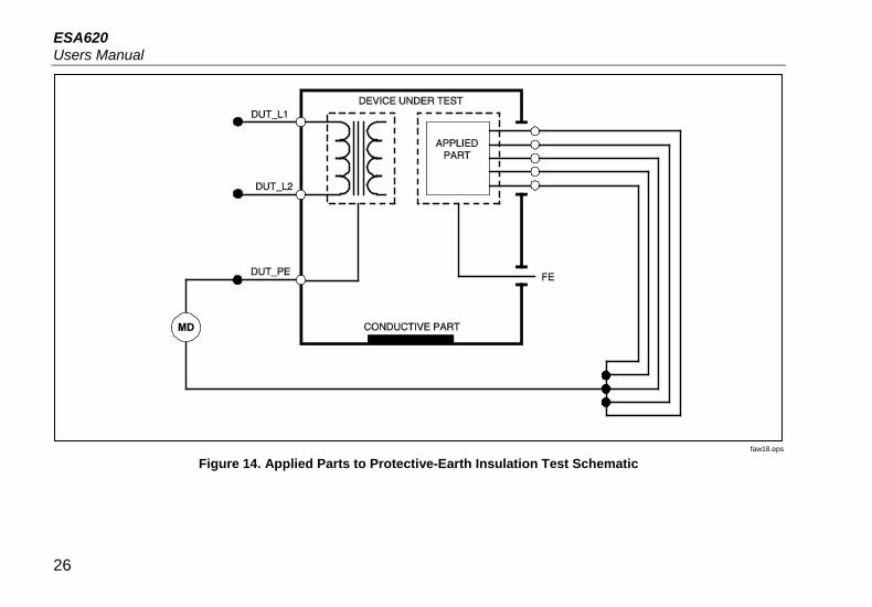
Performing an Insulation Resistance Test The five insulation resistance tests take measurements on mains (L1 & L2) to Protective earth, applied parts to Protective earth, mains to applied parts, mains to non-earthed accessible conductive points, and applied parts to non-earthed accessible conductive points.
To access the Insulation Resistance Test menu, press .
All Insulation Resistance Tests can be performed using 500 or 250 volts dc. To change the test voltage from the Insulation Resistance Test menu, press the softkey labeled More. Pressing the softkey labeled Change Voltage will cause the test voltage to toggle between 250 and 500 volts dc.
Note Exiting and re-entering the Insulation Resistance Test menu causes the test voltage to return to its default value of 500 volts dc.
faw15.eps
Figure 12. Insulation Resistance Measurement
As shown in Figure 12, three of the five tests are shown over function soft keys F1 through F3. To access the other two tests or test voltage selection, press the softkey labeled More. The softkey labeled Back will move the menu back up to the top-level insulation resistance test menu.
After selecting one of the tests by pressing the appropriate softkey, press to apply the selected voltage to the DUT and take the resistance measurement.
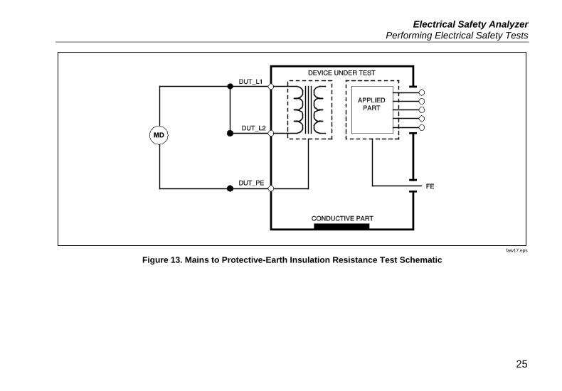
Figure 13 through 17 shows the electrical connections between the Analyzer and DUT for the five insulation resistance tests.
Note The DUT is powered off for this test.
24
Electrical Safety Analyzer Performing Electrical Safety Tests
faw17.eps
Figure 13. Mains to Protective-Earth Insulation Resistance Test Schematic
25
ESA620 Users Manual
faw18.eps
Figure 14. Applied Parts to Protective-Earth Insulation Test Schematic
26

Electrical Safety Analyzer Performing Electrical Safety Tests
faw19.eps
Figure 15. Mains to Applied Parts Insulation Test Schematic
27

ESA620 Users Manual
faw20.eps
Figure 16. Mains to Non-Earth Accessible Conductive Points Schematic
28

Electrical Safety Analyzer Performing Electrical Safety Tests
faw21.eps
Figure 17. Applied Parts to Non-Earth Conductive Points Schematic
29
ESA620 Users Manual
Performing a Current Consumption Test To measure the current consumed by the DUT, press . The Analyzer displays the current flowing through the mains connections of the test receptacle.
Performing Leakage Current Tests The Analyzer measures leakage current for a number of different DUT configurations. In addition to the leakage found on the enclosure and the earth connection, the Analyzer can measure leakage on each connected applied part and combinations of connected applied parts.
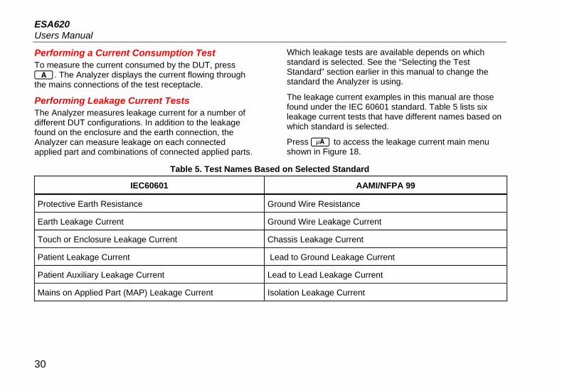
Which leakage tests are available depends on which standard is selected. See the “Selecting the Test Standard” section earlier in this manual to change the standard the Analyzer is using.
The leakage current examples in this manual are those found under the IEC 60601 standard. Table 5 lists six leakage current tests that have different names based on which standard is selected.
Press to access the leakage current main menu shown in Figure 18.
Table 5. Test Names Based on Selected Standard
IEC60601 AAMI/NFPA 99
Protective Earth Resistance Ground Wire Resistance
Earth Leakage Current Ground Wire Leakage Current
Touch or Enclosure Leakage Current Chassis Leakage Current
Patient Leakage Current Lead to Ground Leakage Current
Patient Auxiliary Leakage Current Lead to Lead Leakage Current
Mains on Applied Part (MAP) Leakage Current Isolation Leakage Current
30

Electrical Safety Analyzer Performing Electrical Safety Tests
faw16.eps
Figure 18. Leakage Current Main Menu
Note The display shown in Figure 18 is the main leakage current menu when IEC60601 is the selected standard.
All leakage currents, with the exception of Mains on Applied parts (Lead Isolation), are displayed in one of three ways: AC+DC, AC Only, or DC only. The initial result is displayed in the appropriate parameter based on the standard selected. To change the displayed parameter, press or . The present measurement method is displayed in the upper left corner of the display while leakage current tests are conducted.
Measuring Earth Leakage Current
Note The Earth (or Ground Wire) Leakage test is available for all standards except IEC 62353 and IEC 61010.
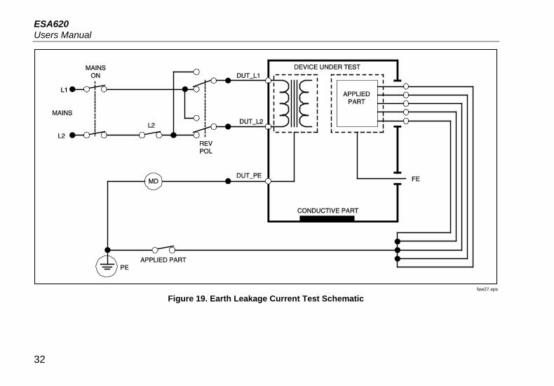
To measure the current flowing in the DUT’s protective earth circuit, press the softkey labeled Earth (pending the standard) from the leakage current main menu. Figure 19 shows the electrical connections between the Analyzer and the DUT during an Earth Leakage Current Test.
Within the Earth Leakage Current test there are a few combination measurements that can be performed. Pressing switches the polarity of the mains voltage applied to the Analyzer’s test receptacle between Normal, Off, Reverse, and Off. Pressing opens and closes the neutral connection to the Analyzer’s test receptacle. There is no need to open up the test receptacle earth (ground), since this is done internally during the measurement.
The following outlet conditions apply when performing this test:
• Normal Polarity • Normal Polarity, Open Neutral • Reversed Polarity • Reversed Polarity, Open Neutral
IEC60601-1 specifies that the applied parts should be connected for this measurement. Enable this measurement by pressing or which grounds and ungrounds all applied parts connection posts.
31
ESA620 Users Manual
faw27.eps
Figure 19. Earth Leakage Current Test Schematic
32

Electrical Safety Analyzer Performing Electrical Safety Tests
Performing an Enclosure Leakage Test
Note The Enclosure Leakage test is only available for the IEC60601 & ANSI/AMMI ES60601-1, ANSI/AAMI ES1 1993, and None standard selections.
The Enclosure Leakage Test measures the current flowing between the DUT’s enclosure and protective earth. Figure 20 shows the electrical connections between the Analyzer and the DUT
To perform an Enclosure (Chassis) Leakage Test:
1. Connect a lead between the Analyzer’s 2-WIRE V/Ω/A jack and the DUT’s enclosure.
2. Press the softkey labeled Enclosure from the Leakage Current Test menu.
3. The Analyzer displays the measured current. The Enclosure Leakage test can be performed with a number of fault conditions on the test receptacle. Press to switch the test receptacle between Normal, Off, Reverse, and Off. Press to open and close the neutral connection to the receptacle. Press to open and close the receptacle’s earth connection.
The following outlet conditions apply when performing this test:
• Normal Polarity • Normal Polarity, Open Earth • Normal Polarity, Open Neutral • Reversed Polarity • Reversed Polarity, Open Earth • Reversed Polarity, Open Neutral
IEC60601-1 specifies that the applied parts should be connected for this measurement. Enable this measurement by pressing or which grounds and ungrounds all applied parts connection posts.
33

ESA620 Users Manual
faw28.eps
Figure 20. Enclosure Leakage Current Test Schematic
34

Electrical Safety Analyzer Performing Electrical Safety Tests
Performing a Patient Leakage Test
Note The Patient Leakage Current Test is not available for IEC 62353 or IEC 61010 standard selections.
The Patient-Leakage Current test measures the current flowing between a selected applied part, selected group of applied parts, or ALL applied parts, and the Mains PE. Figure 21 shows the electrical connections between the Analyzer and the DUT.
To perform a patient leakage test:
1. Press .
2. Press the soft key labeled More.
3. Select one of the applied part groupings by pressing or .
Note Refer to the testing standard when deciding the type of the applied parts and how they should be grouped for testing.
4. Press the soft key labeled Select. 5. Press or to advance through each applied part
grouping, or the individual applied parts, to ground. These are selected and measured.
The Patient Leakage test can be performed with a number of fault conditions on the test receptacle. Press to switch the test receptacle between Normal, Off, Reverse, and Off. Press to open and close the neutral connection to the receptacle. Press to open and close the receptacle’s earth connection.
The following outlet conditions apply when performing this test:
• Normal Polarity • Normal Polarity, Open Neutral • Normal Polarity, Open Earth • Reversed Polarity • Reversed Polarity, Open Neutral • Reversed Polarity, Open Earth
35

ESA620 Users Manual
gtv29.eps
Figure 21. Patient Leakage Current Test Schematic
36

Electrical Safety Analyzer Performing Electrical Safety Tests
Performing Patient Auxiliary Leakage Tests
Note The Patient Auxiliary leakage test is available when the AN/NZS3551, IEC60601, or ANSI/AAMI ES1-1993 standard is selected.
To measure the leakage current through each applied part or lead and selected combination of lead connections (all other or between two), press the softkey labeled Patient Auxiliary from the Leakage Test main menu shown in Figure 18. Figure 23 shows the electrical connections between the Analyzer and the DUT during a Patient Auxiliary Leakage Current Test.
The Patient Auxiliary Leakage test adds a diagram of the applied parts connection posts to the display, as shown in Figure 22. In the Figure, the applied parts post RA/R is shown above the other posts. This indicates that the leakage measurement is being made from RA/R to all others. To move to the next applied part post, press . The first post will appear inline with the other posts while the LL/F post appears above all others. This indicates the second leakage measurement is being made from LL/F to all others. Continue pressing or to move from one connection post to another and noting the measured current in the display.
After each post is isolated individually, the Patient Auxiliary Leakage test measures current of three different combinations of posts tied together: RA/R and LL/F, RA/R and LA/L, or LL/F and LA/L.
faw10.eps
Figure 22. Applied Parts Connection Posts Display
Within the Patient Auxiliary Leakage test, a number of fault measurements can be made. Pressing switches the polarity of the mains voltage applied to the Analyzer’s test receptacle between Normal, Off, Reverse, and Off. Pressing opens and closes the neutral connection to the Analyzer’s test receptacle. Pressing opens and closes the earth or ground connection to the Analyzer’s test receptacle.
37

ESA620 Users Manual
gtv30.eps
Figure 23. Patient Auxiliary Leakage Current Test Schematic
38

Electrical Safety Analyzer Performing Electrical Safety Tests
The following outlet conditions apply when performing this test:
• Normal Polarity • Normal Polarity, Open Neutral • Normal Polarity, Open Earth • Reversed Polarity, Open Neutral • Reversed Polarity, Open Earth
Performing a Mains on Applied Part Leakage Test
Note The Mains on Applied Part leakage test is available when the IEC60601 & ANSI/AAMI ES60601-1 or AN/NZS 3551 standard is selected.
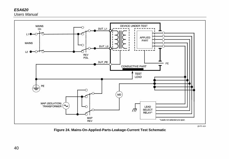
The Mains-On-Applied-Parts-Leakage-Current test measures the current that flows in response to an isolated AC voltage applied between a selected applied part, group of applied parts, or ALL applied parts, and Earth (and any conductive part connected to the RED terminal). Figure 24 shows the electrical connections between the Analyzer and the DUT during a Mains on Applied Part Leakage Current Test.
To perform a mains on applied part test:
1. Press .
2. Press the soft key labeled More.
3. Select the desired applied part groupings using and .
Note Refer to the testing standard when deciding the type of the applied parts and how they should be grouped for testing.
4. Press the soft key labeled Select. 5. Press the soft key labeled Mains on A. P.
6. Press or to select the desired applied part connection.
7. Press to apply the voltage and read the leakage current in the display.
Pressing and scrolls through the applied part connections or groupings. Press for each connection configuration to thoroughly test the DUT.
The following outlet conditions apply when performing this test:
• Normal Polarity • Reverse Polarity
39
ESA620 Users Manual
gtv31.eps
Figure 24. Mains-On-Applied-Parts-Leakage-Current Test Schematic
40

Electrical Safety Analyzer Performing Electrical Safety Tests
Performing an Alternative Equipment Leakage Test
Note The alternative equipment leakage test is available when the EN62353 & VDE 751 standard is selected.
During the Alternative Equipment Leakage test, the voltage source is applied between short-circuited equipment outlet mains live, neutral, and equipment outlet earth, the exposed conductive surface on the housing, and all applied parts short-circuited together. Equipment is separated from mains during the test. The current which flows over the insulation of the DUT is measured.
This test is not applicable for equipment with internal electrical power source. The switches in mains part shall be closed during measurement.
To perform an alternative equipment leakage test:
1. Press . The alternative equipment test is the default test and should already be selected.
2. Press to apply the voltage and read the current in the display.
Figure 25 shows the electrical connections between the Analyzer and the DUT during a Alternative Equipment Leakage Test.
The following outlet conditions apply when performing this test:
• Closed Earth • Open Earth
Performing an Alternative Applied Part Leakage Test
Note The Alternative applied part leakage test is available when the EN62353 & VDE 751 standard is selected.
During the Alternative Applied Part Leakage test, the test voltage is applied between short-circuited applied parts of a single function and the short-circuited equipment outlet mains live, neutral, equipment outlet earth, and exposed conductive surface on the housing. This test should only be done for equipment with F-Type applied parts. For equipment with multiple applied parts, test each group of applied parts of a single function in turn with all others floating during the test. All applied parts can be connected to the Analyzer’s applied parts jacks and the lead selection will float those not selected.
41

ESA620 Users Manual
faw22.eps
Figure 25. Alternative Equipment Leakage Current Test Schematic
42

Electrical Safety Analyzer Performing Electrical Safety Tests
gtv23.eps
Figure 26. Alternative Applied Part Leakage Test Schematic
43
ESA620 Users Manual
To perform an alternative applied part leakage test:
1. Press .
2. Press the soft key labeled More.
3. Select the desired applied part groupings using and .
4. Press the soft key labeled Select. 5. Press the soft key labeled Alternative A.P.. 6. Press to apply the test voltage and read the
current in the display.
7. Press or to advance to the next applied part group(s) of a single function if applicable. Pressing to read leakage current for each group.
Figure 26 shows the electrical connections between the Analyzer and the DUT during an Alternative Applied Part Leakage current test.
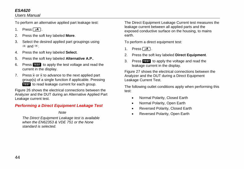
Performing a Direct Equipment Leakage Test Note
The Direct Equipment Leakage test is available when the EN62353 & VDE 751 or the None standard is selected.
The Direct Equipment Leakage Current test measures the leakage current between all applied parts and the exposed conductive surface on the housing, to mains earth.
To perform a direct equipment test:
1. Press .
2. Press the soft key labeled Direct Equipment. 3. Press to apply the voltage and read the
leakage current in the display. Figure 27 shows the electrical connections between the Analyzer and the DUT during a Direct Equipment Leakage Current Test.
The following outlet conditions apply when performing this test:
• Normal Polarity, Closed Earth • Normal Polarity, Open Earth • Reversed Polarity, Closed Earth • Reversed Polarity, Open Earth
44

Electrical Safety Analyzer Performing Electrical Safety Tests
faw24.eps
Figure 27. Direct Equipment Leakage Test Schematic
45
ESA620 Users Manual
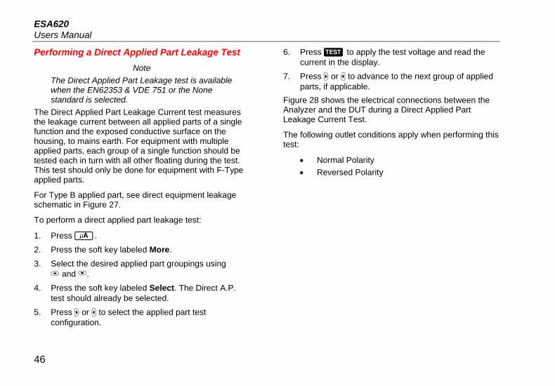
Performing a Direct Applied Part Leakage Test Note
The Direct Applied Part Leakage test is available when the EN62353 & VDE 751 or the None standard is selected.
The Direct Applied Part Leakage Current test measures the leakage current between all applied parts of a single function and the exposed conductive surface on the housing, to mains earth. For equipment with multiple applied parts, each group of a single function should be tested each in turn with all other floating during the test. This test should only be done for equipment with F-Type applied parts.
For Type B applied part, see direct equipment leakage schematic in Figure 27.
To perform a direct applied part leakage test:
1. Press .
2. Press the soft key labeled More.
3. Select the desired applied part groupings using and .
4. Press the soft key labeled Select. The Direct A.P. test should already be selected.
5. Press or to select the applied part test configuration.
6. Press to apply the test voltage and read the current in the display.
7. Press or to advance to the next group of applied parts, if applicable.
Figure 28 shows the electrical connections between the Analyzer and the DUT during a Direct Applied Part Leakage Current Test.
The following outlet conditions apply when performing this test:
• Normal Polarity • Reversed Polarity
46

Electrical Safety Analyzer Performing Electrical Safety Tests
gtv25.eps
Figure 28. Direct Applied Parts Leakage Current Test Schematic
47

ESA620 Users Manual
Performing a Differential Leakage Current Test Note
The Differential Leakage Current test is available when the EN62353 & VDE 751 or the None standard is selected.
The differential leakage current test measures the magnitudes of the differential current flowing in the Equipment Outlet live and neutral, with power applied to the equipment outlet. All applied parts should be connected during this test, if equipment has applicable applied parts.
To perform a differential leakage current test:
1. Press .
2. Press the soft key labeled Differential. Figure 29 shows the electrical connections between the Analyzer and the DUT during a Differential Leakage Current test.
The following outlet conditions apply when performing this test:
• Normal Polarity, Closed Earth • Normal Polarity, Open Earth • Reversed Polarity, Closed Earth • Reversed Polarity, Open Earth
Performing an Accessible Leakage Current Test (IEC 61010 only)
Note The Accessible Leakage Current test selection will only appear in the Analyzer’s menu when the standard is set to IEC61010.
To perform an accessible leakage current test:
1. Press .
2. Read the leakage current in the display. The following outlet conditions apply when performing this test:
• Normal Polarity • Normal Polarity, Open Neutral • Normal Polarity, Open Earth • Reversed Polarity • Reversed Polarity, Open Neutral • Reversed Polarity, Open Earth
48

Electrical Safety Analyzer Performing Electrical Safety Tests
gtv32.eps
Figure 29. Differential Leakage Current Test Schematic
49

ESA620 Users Manual
Making Point-To-Point Measurements The Analyzer can make voltage, resistance, and low current measurements through its Point-to-Point function. To access the Point-to-Point function menu shown in Figure 30, press . Softkeys F1 through F3 are used to select the measurement function.
faw08.eps
Figure 30. Point-To-Point Function Menu
Measuring Voltage To make a voltage measurement:
1. Press the softkey labeled Voltage from the Point-To-Point menu.
2. Insert test leads in the RED and BLACK 2-Wire V/Ω/A jacks.
3. Place the probe tips across the unknown voltage and read the measurement in the Analyzer’s display.
The Analyzer will measure up to 300 volts ac.
Measuring Resistance The Analyzer can make 2-Wire or 4-Wire resistance measurements. To switch between these methods, see the “Selecting 2-Wire or 4-Wire Measurements” section.
To make a resistance measurement:
1. Press the softkey labeled Resistance from the Point-To-Point menu.
2. Insert test leads in the RED and BLACK 2-Wire V/Ω/A jacks. For 4-Wire measurements, two additional leads need to be inserted into the RED and BLACK 4 Wire Source jacks.
3. Place the probes across the unknown resistance and read the measurement in the Analyzer’s display.
The Analyzer will measure resistances up to 2.0 Ω.
50

Electrical Safety Analyzer Simulating ECG Waveforms
Measuring Current The Analyzer can make dc only, ac only, and ac+dc current measurements up to 10 mA. To make a current measurement:
1. Press the softkey labeled Leakage from the Point-To-Point menu.
2. Using or select between ac only, dc only, or ac+dc measurement mode.
3. Insert test leads in the RED and BLACK 2-Wire V/Ω/A jacks.
Place the leads on the two points the unknown current may flow and read the measurement in the Analyzer’s display.
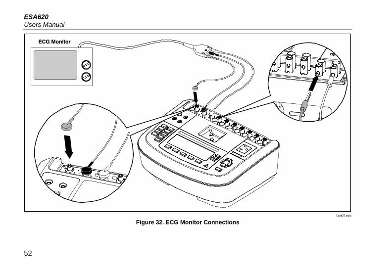
Simulating ECG Waveforms The Analyzer is capable of generating various waveforms on the applied parts connection posts. These signals are used to test the performance characteristics of ECG monitors and ECG strip printers. See Figure 32 for proper connections between the Analyzer and an ECG monitor.
To access the ECG Simulation Waveform menu shown in Figure 31, press . From this menu, a number of different waveforms are selected through F1, and the rate or frequency of the waveform is selected through F2.
faw09.eps
Figure 31. ECG Waveform Simulation Menu
To select one of the predefined waveforms, press the softkey labeled Wave Form. A scroll box with next to it appears above the softkey label. Use or to scroll through the different waveforms.
For all waveforms except VFIB and Triangle, the rate or frequency of the waveform is adjusted through the softkey labeled Frequency or Rate. For some waveforms, there are more than two frequency or rate selections. For those waveforms, pressing the softkey labeled Frequency or Rate will open a scroll box above the softkey label with next to it. Use or to select the frequency or rate. For those waveforms that have only two frequency or rate selections, the softkey labeled Frequency or Rate acts as a toggle, where each press of the softkey switches to the other value.
51
ESA620 Users Manual
faw07.eps
Figure 32. ECG Monitor Connections
52

Electrical Safety Analyzer Controlling the Analyzer Remotely
Controlling the Analyzer Remotely Fluke Biomedical Ansur test automation software allows a solutions-based approach to complete testing of the medical device under test (DUT). Ansur helps create standard work using the test template/sequence (which is based on a user written test procedure), and integrates all test results into a single test report which can be printed or archived. Ansur allows for automatic comparisons to the limits of the standard selected, indicating whether results are passing or failing. Ansur manages test procedures by allowing both manual and visual automated test sequences.
The software works hand-in-hand with Fluke Biomedical analyzers and simulators, creating a seamless integration for:
• Visual inspections • Preventive maintenance • Work procedures • Performance tests • Safety tests
Ansur software utilizes plug-in modules to work with a wide array of Fluke Biomedical instruments. The plug-in module is a software interface to the Ansur test program. The plug-in modules are available for purchase as an optional accessory. Plug-ins provide test elements used by Ansur. This has the benefit of using the same user interface for all analyzers and simulators supported by an Ansur plug-in.
When a new Fluke Biomedical analyzer or simulator is purchased, simply update your existing Ansur software by installing a new plug-in. Each plug-in module works only with the options and capabilities needed for the instrument being tested.
Maintenance The Analyzer needs little maintenance or special care. However, treat it as a calibrated measuring instrument. Avoid dropping or other mechanical abuse that could cause a shift in the calibrated settings.
53

ESA620 Users Manual
Cleaning the Analyzer Warning
To avoid electric shock, do not clean the Analyzer plugged into mains or attached to a DUT.
Caution Do not pour fluid onto the Analyzer surface; fluid seepage into the electrical circuitry may cause the Analyzer to fail.
Caution Do not use spray cleaners on the Analyzer; such action may force cleaning fluid into the Analyzer and damage electronic components.
Clean the Analyzer occasionally utilizing a damp cloth and mild detergent. Take care to prevent the entrance of liquids.
Wipe down the adapter cables with the same care. Inspect them for damage to and deterioration of the insulation. Check the connections for integrity before each use.
54

Electrical Safety Analyzer Replaceable Parts
Replaceable Parts Table 6 lists the replaceable parts for the Analyzer.
Table 6. Replaceable Parts
Item Fluke Biomedical Part Number
ESA620 Getting Started Manual 2814971
ESA620 Users Manual CD 2814967
Power Cord
USA 2238680
UK 2238596
Australia 2238603
Europe 2238615
France/Belgium 2238615
Italy 2238615
Israel 2434122
Ansur, CD with demo version 2795488
Test Probe Set USA, Australia, & Israel 650887
Europe 1541649
55

ESA620 Users Manual
Table 6. Replaceable Parts (cont.)
Item Fluke Biomedical Part Number
Null Post Adapter 3326842
Carrying Case 2814980
Data Transfer Cable 1626219
T20A 250V Fuse (Time Lag), 1¼ in x ¼ in 2183691
T10A 250V Fuse (Time Lag), 5 x 20 mm 3046641
T16A 250V Fuse (Time Lag), 5 x 20 mm 3056494
15 – 20 A Adapter 2195732
To ensure safety, use exact replacement only.
56
Electrical Safety Analyzer Accessories
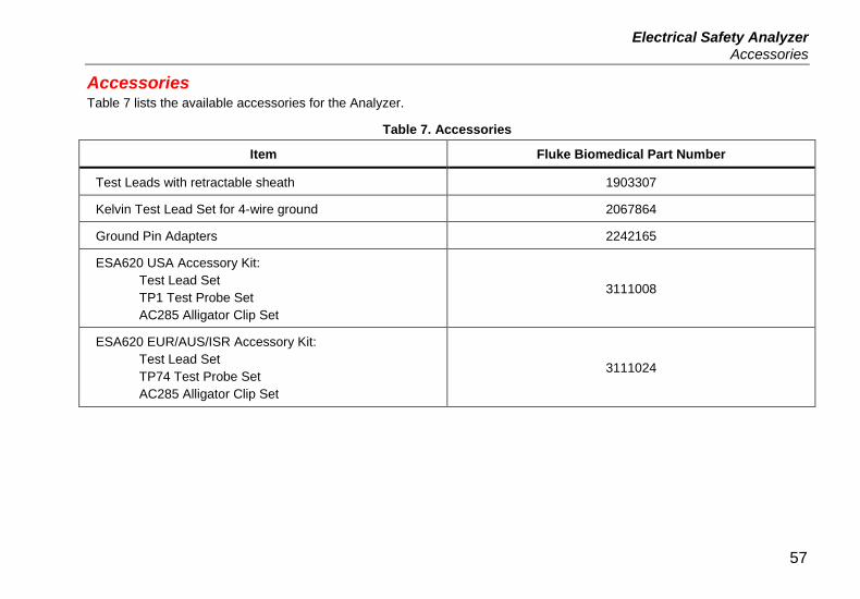
Accessories Table 7 lists the available accessories for the Analyzer.
Table 7. Accessories
Item Fluke Biomedical Part Number
Test Leads with retractable sheath 1903307
Kelvin Test Lead Set for 4-wire ground 2067864
Ground Pin Adapters 2242165
ESA620 USA Accessory Kit: Test Lead Set TP1 Test Probe Set AC285 Alligator Clip Set
3111008
ESA620 EUR/AUS/ISR Accessory Kit: Test Lead Set TP74 Test Probe Set AC285 Alligator Clip Set
3111024
57

ESA620 Users Manual
Specifications Temperature
Operating ............................................................ 10 °C to 40 °C (50 °F to 104 °F) Storage ............................................................... -20 °C to 60 °C (-4 °F to 140 °F)
Humidity ................................................................. 10 % to 90 % non-condensing Altitude ................................................................... To 5,000 meters @ 115 V ac mains and ≤150 V measurements
To 2,000 meters @ 230 V ac mains and ≤300 V measurements Display ................................................................... LCD display Communications ................................................... USB device port for computer control Modes of Operation .............................................. Manual and remote Power
120 Volt power outlet .......................................... 90 to 132 V ac rms, 47 to 63 Hz, 20 A maximum 230 Volt power outlet .......................................... 180 to 264 V ac rms, 47 to 63 Hz, 16 A maximum
Size (L x W x H) ..................................................... 32 cm x 23.6 cm x 12.7 cm (12.6 in x 9.3 in x 5 in) Weight .................................................................... 4.7 kg (10.25 lb) Safety ..................................................................... IEC 61010-1: Overvoltage category II, Pollution Degree 2
IEC 61010-2-030: Measurement 300 V, CAT II Electromagnetic Compatibility (EMC)
International ...................................................... IEC 61326-1: Controlled Electromagnetic Environment CISPR 11: Group 1, Class A
Group 1: Equipment has intentionally generated and/or uses conductively-coupled radio frequency energy that is necessary for the internal function of the equipment itself. Class A: Equipment is suitable for use in all establishments other than domestic and those directly connected to a low-voltage power supply network that supplies buildings used for domestic purposes. There may be potential difficulties in ensuring
58

Electrical Safety Analyzer Detailed Specifications
electromagnetic compatibility in other environments due to conducted and radiated disturbances. Emissions that exceed the levels required by CISPR 11 can occur when the equipment is connected to a test object.
Korea (KCC) ........................................................ Class A Equipment (Industrial Broadcasting & Communication Equipment) Class A: Equipment meets requirements for industrial electromagnetic wave equipment and the seller or user should take notice of it. This equipment is intended for use in business environments and not to be used in homes.
USA (FCC) .......................................................... 47 CFR 15 subpart B. This product is considered an exempt device per clause.
Detailed Specifications Voltage
Mains voltage Ranges ............................................................ 0.0 to 300 V ac rms Accuracy ......................................................... ±(2 % of reading + 1.0 V ac)
Accessible Voltage and Point to Point Voltage Range .............................................................. 0.0 to 300 V ac rms Accuracy ......................................................... ±(2 % of reading + 2 LSD)
Earth Resistance Modes.................................................................. Two terminal and four terminal Test Current ........................................................ >200 mA ac into 500 mΩ with open circuit voltage ≤ 24 V
25 A short circuit ±10 % (with open circuit voltage 6 Vac at nominal mains) Range .................................................................. 0.0 to 2.0 Ω Accuracy
Two Terminal Mode Test current >200 mA ac into 500 mΩ ........ ±(2 % of reading + 0.015 Ω) for 0.0 to 2.0 Ω Test current 1-16 A ac ................................ ±(2 % of reading + 0.015 Ω) for 0.0 to 0.2 Ω
±(5 % of reading + 0.015 Ω) for 0.2 to 2.0 Ω
59

ESA620 Users Manual
Four Terminal Mode Test current >200 mA ac into 500 mΩ ........ ±(2 % of reading + 0.005 Ω) for 0.0 to 2.0 Ω
Test current 1-16 A ac ........................................ ±(2 % of reading + 0.005 Ω) for 0.0 to 0.2 Ω ±(5 % of reading + 0.005 Ω) for 0.2 to 2.0 Ω
Additional error caused by series inductance
Resistance Series Inductance
0 µH 100 µH 200 µH 400 µH
0.000 Ω 0.000 Ω 0.030 Ω 0.040 Ω 0.050 Ω
0.020 Ω 0.000 Ω 0.025 Ω 0.030 Ω 0.040 Ω
0.040 Ω 0.000 Ω 0.020 Ω 0.025 Ω 0.030 Ω
0.060 Ω 0.000 Ω 0.015 Ω 0.020 Ω 0.025 Ω
0.080 Ω 0.000 Ω 0.010 Ω 0.015 Ω 0.020 Ω
0.100 Ω 0.000 Ω 0.010 Ω 0.010 Ω 0.015 Ω
>0.100 Ω 0.000 Ω 0.010 Ω 0.010 Ω 0.010 Ω
Equipment Current Range ................................................................. 0 – 20 A ac rms Accuracy ............................................................. 5 % of reading ± (2 counts or 0.2A, whichever is greater) Duty cycle ........................................................... 15 A to 20 A, 5 min. on/5 min. off
10 A to 15 A, 7 min. on/3 min. off 0 A to 10 A continuous
60
Electrical Safety Analyzer Detailed Specifications
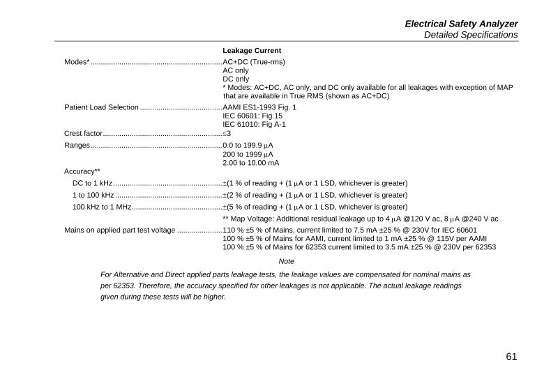
Leakage Current Modes* ................................................................ AC+DC (True-rms)
AC only DC only * Modes: AC+DC, AC only, and DC only available for all leakages with exception of MAP that are available in True RMS (shown as AC+DC)
Patient Load Selection ........................................ AAMI ES1-1993 Fig. 1 IEC 60601: Fig 15 IEC 61010: Fig A-1
Crest factor .......................................................... ≤3 Ranges ................................................................ 0.0 to 199.9 µA
200 to 1999 µA 2.00 to 10.00 mA
Accuracy** DC to 1 kHz ..................................................... ±(1 % of reading + (1 µA or 1 LSD, whichever is greater) 1 to 100 kHz .................................................... ±(2 % of reading + (1 µA or 1 LSD, whichever is greater) 100 kHz to 1 MHz ............................................ ±(5 % of reading + (1 µA or 1 LSD, whichever is greater)
** Map Voltage: Additional residual leakage up to 4 µA @120 V ac, 8 µA @240 V ac Mains on applied part test voltage ...................... 110 % ±5 % of Mains, current limited to 7.5 mA ±25 % @ 230V for IEC 60601
100 % ±5 % of Mains for AAMI, current limited to 1 mA ±25 % @ 115V per AAMI 100 % ±5 % of Mains for 62353 current limited to 3.5 mA ±25 % @ 230V per 62353
Note
For Alternative and Direct applied parts leakage tests, the leakage values are compensated for nominal mains as per 62353. Therefore, the accuracy specified for other leakages is not applicable. The actual leakage readings given during these tests will be higher.
61

ESA620 Users Manual
Differential leakage Ranges ............................................................... 50 to 199 µA
200 to 2000 µA 2.00 to 20.00 mA
Accuracy ............................................................. ± 10 % of reading ± (2 counts or 20 µA, whichever is greater) Insulation resistance
Ranges ............................................................... 0.5 to 20 MΩ 20 to 100 MΩ
Accuracy 20 MΩ Range .................................................. ±(2 % of reading + 2 counts) 100 MΩ Range ................................................ ±(7.5 % of reading + 2 counts)
Source test voltage ............................................. 500 V dc (+20 %, -0 %) 1.5 mA short-circuit current or 250 V dc selectable Maximum load capacitance ................................ 1 µF
ECG Performance Waveforms Accuracy ............................................................. ±2 %
±5 % for amplitude of 2 Hz square wave only, fixed @ 1 mV Lead II configuration Waveforms
ECG Complex ................................................. 30, 60, 120, 180, and 240 BPM Ventricular Fibrillation Square wave (50 % duty cycle) ...................... 0.125 and 2 Sine wave ....................................................... 10, 40, 50, 60, and 100 Hz Triangle wave .................................................. 2 Hz Pulse (63 ms pulse width ................................ 30 and 60
62