Electrical Metrology - NIST
74
Electrical Metrology Dave Inglis Visiting Worker, NRC, Canada NIST/SIM Metrology School, Gaithersburg, MD, October, 2013
Transcript of Electrical Metrology - NIST
Electrical Metrology
Dave Inglis
Visiting Worker,
NRC, Canada
NIST/SIM Metrology
School,
Gaithersburg, MD,
October, 2013

With many thanks to
Barry Wood
Piotr Filipski
Ken Kochav
for help with some slides and
photographs.
Outline
• Electrical units within the SI
• Electrical units in an NMI or DI
• Realisation of electrical units
•Traceability of electrical units
•Measurement methods
•Measurement issues.
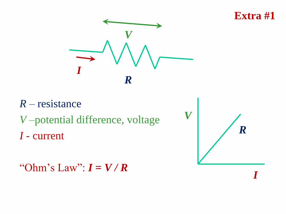
R – resistance
V –potential difference, voltage
I - current
“Ohm’s Law”: I = V / R
I
V
R
V
I
R
Extra #1
Extra #2
C
V
I
+
+
+
+
-
-
-
-
insulator
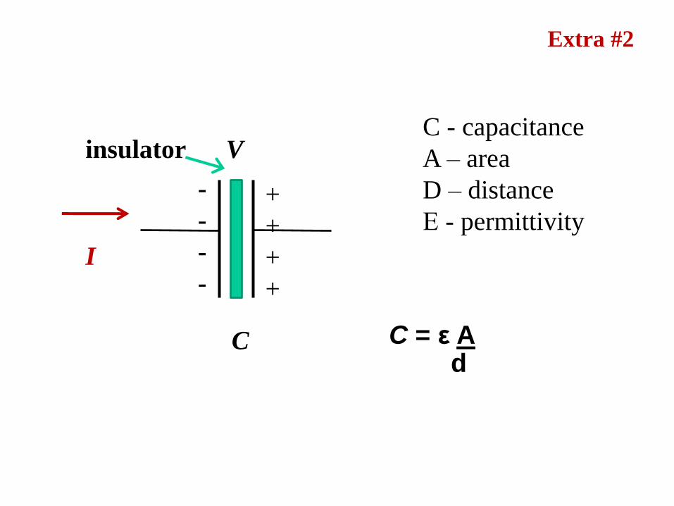
C = ε A d
C - capacitance
A – area
D – distance
Ε - permittivity
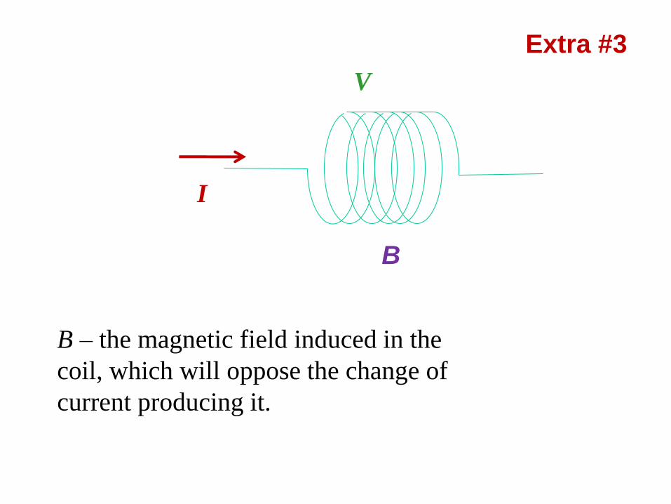
Extra #3
I
B
V
B – the magnetic field induced in the
coil, which will oppose the change of
current producing it.
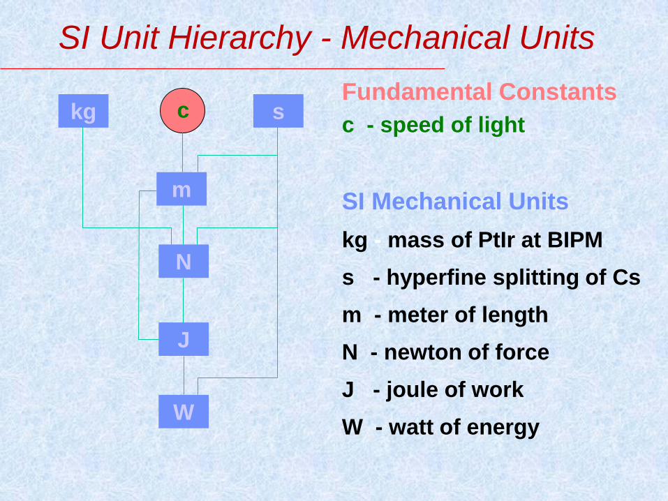
SI Unit Hierarchy - Mechanical Units
kg
m
s
N
J
W
c Fundamental Constants
c - speed of light
SI Mechanical Units
kg - mass of PtIr at BIPM
s - hyperfine splitting of Cs
m - meter of length
N - newton of force
J - joule of work
W - watt of energy

SI Unit Hierarchy & Electrical Units
kg
m
s
N
J
W
c
A
C V
F
permeability
of vacuum
(1948)

Rayleigh Ampere Balance
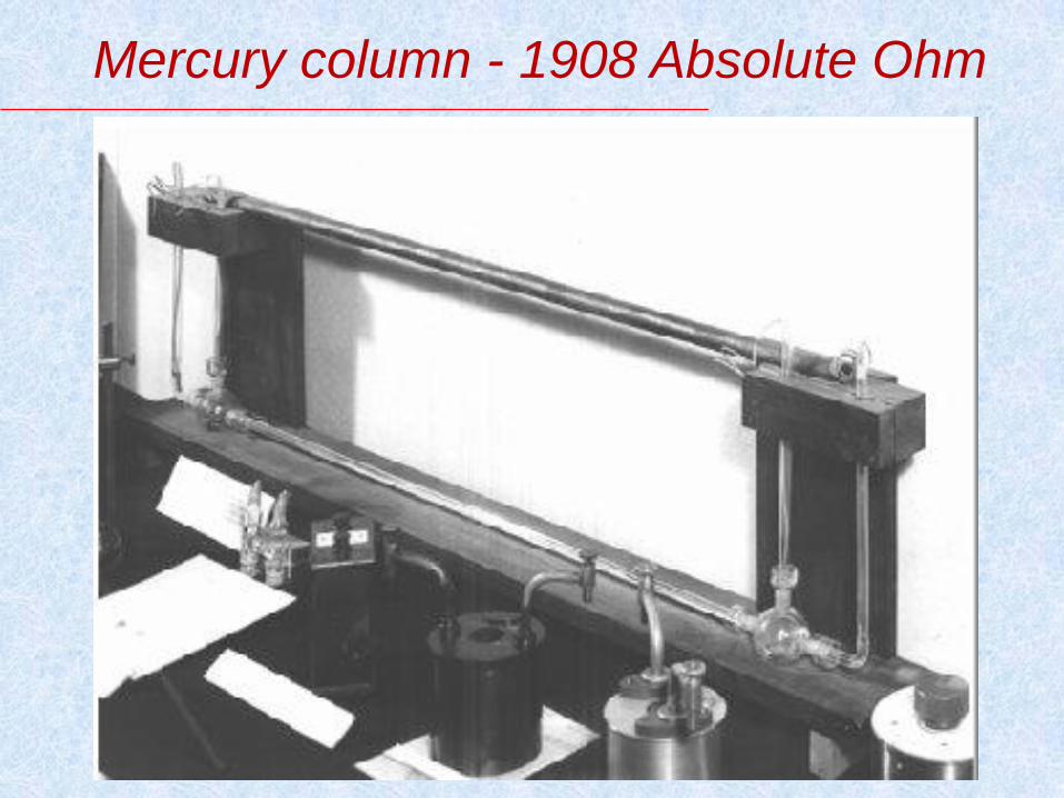
Mercury column - 1908 Absolute Ohm
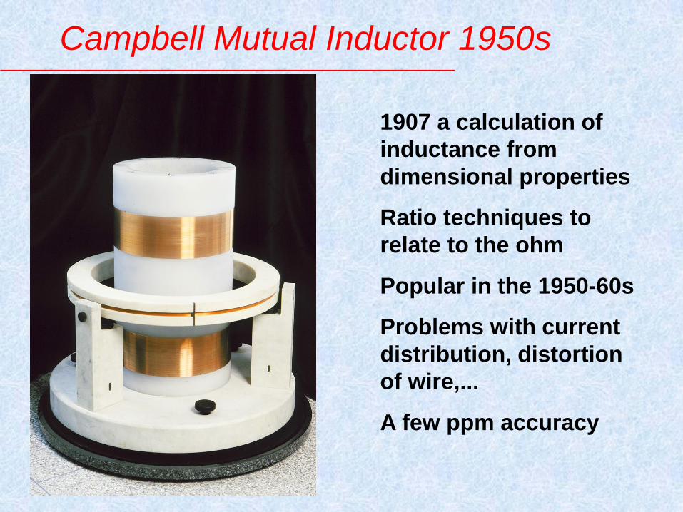
Campbell Mutual Inductor 1950s
1907 a calculation of
inductance from
dimensional properties
Ratio techniques to
relate to the ohm
Popular in the 1950-60s
Problems with current
distribution, distortion
of wire,...
A few ppm accuracy
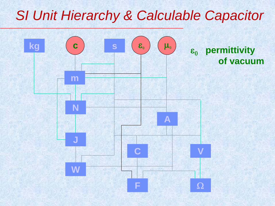
SI Unit Hierarchy & Calculable Capacitor
kg
m
s
N
J
W
c
A
C V
F
e e permittivity
of vacuum
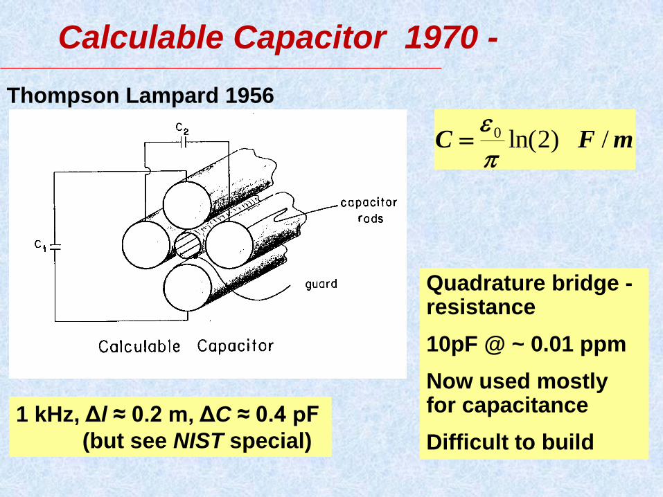
Calculable Capacitor 1970 -
mFC /)2ln(0
e
Thompson Lampard 1956
Quadrature bridge - resistance
10pF @ ~ 0.01 ppm
Now used mostly for capacitance
Difficult to build
1 kHz, Δl ≈ 0.2 m, ΔC ≈ 0.4 pF
(but see NIST special)
BIPM web-site
Oct. 2013
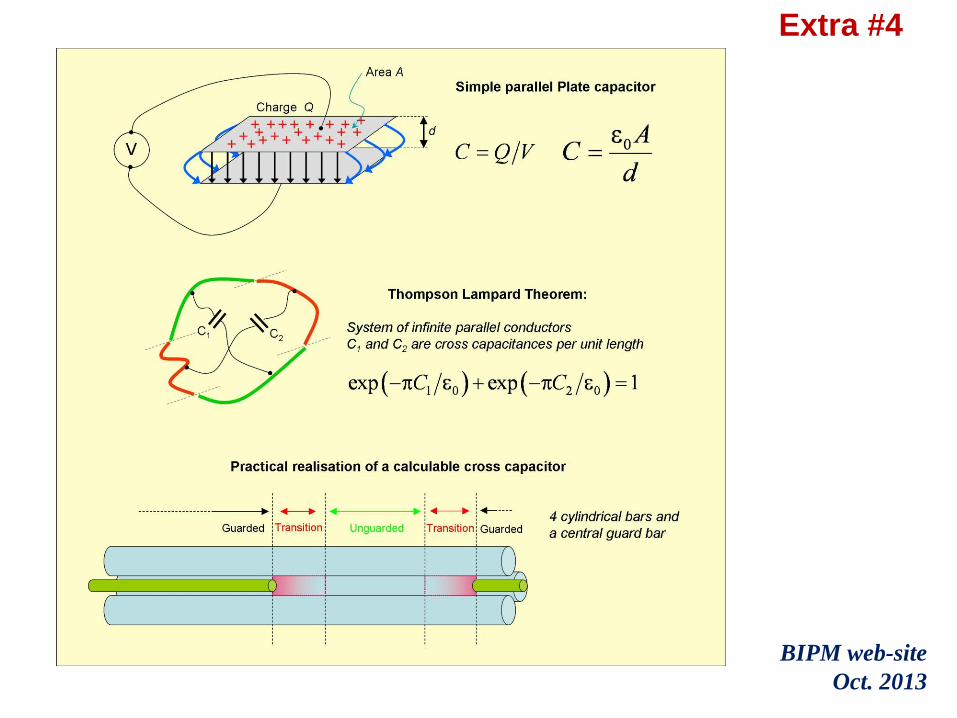
Extra #4

SI Unit Hierarchy & Josephson Effect
kg
m
s
N
J
W
c
A
C V
F
e 2e/h
h
Planck’s
constant
e
electron
charge
The Josephson representation of the SI volt

SI Unit Hierarchy today
kg
m
s
N
J
W
c
A
C V
F
e 2e/h h/e2
e permittivity
of vacuum
h Planck’s
constant
e electron
charge
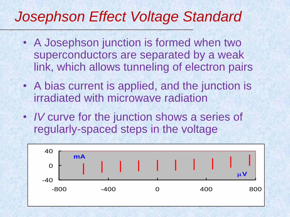
Josephson Effect Voltage Standard
• A Josephson junction is formed when two superconductors are separated by a weak link, which allows tunneling of electron pairs
• A bias current is applied, and the junction is irradiated with microwave radiation
• IV curve for the junction shows a series of regularly-spaced steps in the voltage
-40
0
40
-800 -400 0 400 800
V
mA

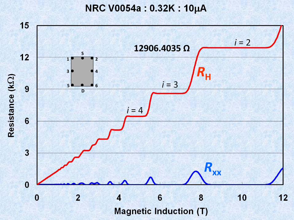
Quantum Hall Resistance 1990-
Internationally accepted
Easier to realize
Accurate < 0.003 ppm
RK-90 = 25812.807
Rxy=Vxy/I
Rxx=Vxx/I
VOLTAGE
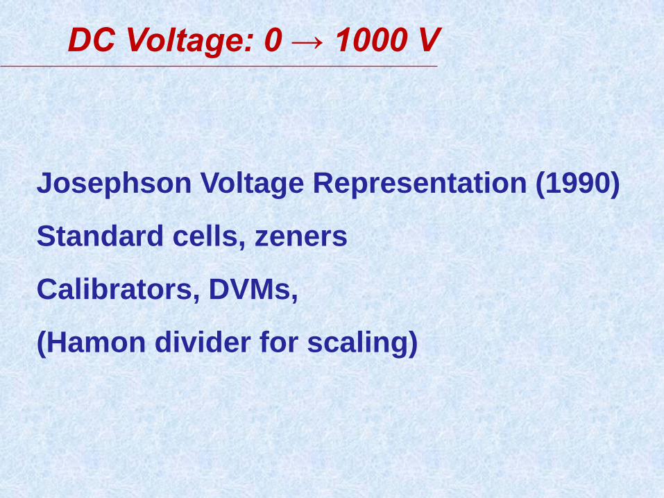
DC Voltage: 0 → 1000 V
Josephson Voltage Representation (1990)
Standard cells, zeners
Calibrators, DVMs,
(Hamon divider for scaling)
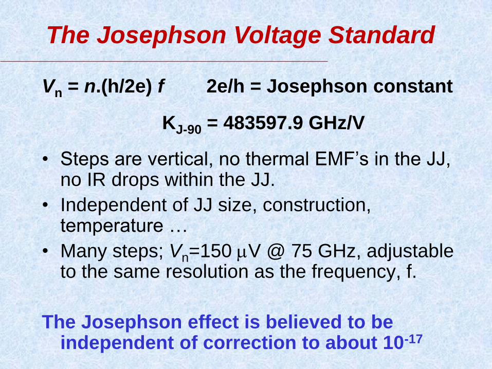
Vn = n.(h/2e) f 2e/h = Josephson constant
KJ-90 = 483597.9 GHz/V
• Steps are vertical, no thermal EMF’s in the JJ, no IR drops within the JJ.
• Independent of JJ size, construction, temperature …
• Many steps; Vn=150 V @ 75 GHz, adjustable to the same resolution as the frequency, f.
The Josephson effect is believed to be independent of correction to about 10-17
The Josephson Voltage Standard
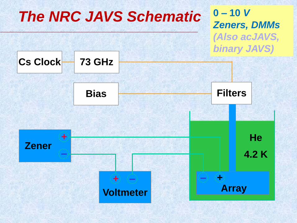
The NRC JAVS Schematic
73 GHz
Bias
Cs Clock
Zener +
–
Voltmeter
+ –
Filters
Array – +
He
4.2 K
0 – 10 V
Zeners, DMMs
(Also acJAVS,
binary JAVS)
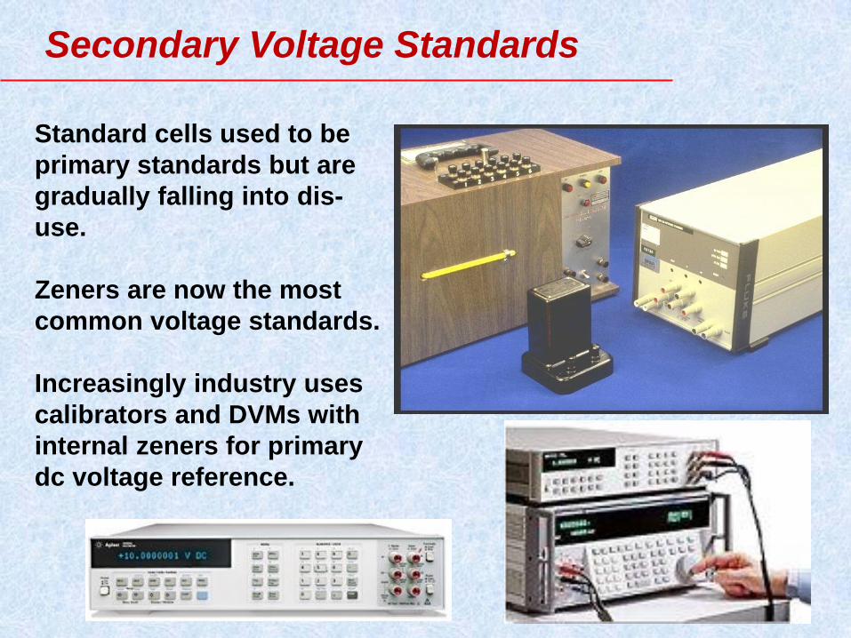
Standard cells used to be
primary standards but are
gradually falling into dis-
use.
Zeners are now the most
common voltage standards.
Increasingly industry uses
calibrators and DVMs with
internal zeners for primary
dc voltage reference.
Secondary Voltage Standards

Zener stability - AC Power or Battery
-2.0
-1.0
0.0
1.0
2.0
12-Nov 26-Nov 10-Dec 24-Dec 7-Jan
1V 1.018V 10V
Fluke Model 732A
Battery
AC Power
p
p
m
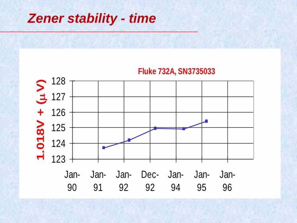
Zener stability - time
123
124
125
126
127
128
Jan-
90
Jan-
91
Jan-
92
Dec-
92
Jan-
94
Jan-
95
Jan-
96
1.0
18V
+ (
V
)
Fluke 732A, SN3735033

Zener stability - time
123
124
125
126
127
128
Jan-
90
Jan-
91
Jan-
92
Dec-
92
Jan-
94
Jan-
95
Jan-
96
1.0
18V
+ (
V
)
Fluke 732A, SN3735033

DC Voltage Summary
Primary standards Josephson Arrays
10 V (
0.001x10⁻⁶)
Secondary standards standard cells, zeners(Fluke 732B),
DVMs and calibrators
1 mV to 1000 V (
1x10⁻⁶ – 0.02x10⁻⁶)
Detectors EM Amplifiers,
HP3458A, Keithley NanoVoltmeters
Scaling JJ Arrays to 10V,
Resistive Dividers, Bootstrap
techniques for higher voltages
Scaling to 1 MV is possible

RESISTANCE
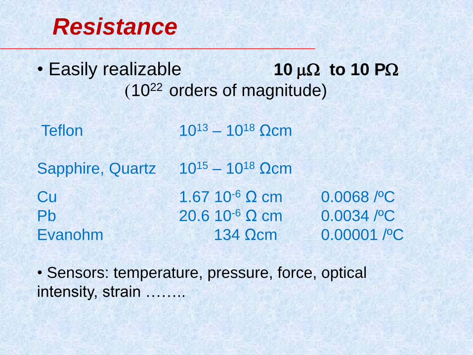
Resistance
• Easily realizable 10 to 10 P
(1022 orders of magnitude)
Teflon 1013 – 1018 Ωcm
Sapphire, Quartz 1015 – 1018 Ωcm
Cu 1.67 10-6 Ω cm 0.0068 /ºC
Pb 20.6 10-6 Ω cm 0.0034 /ºC
Evanohm 134 Ωcm 0.00001 /ºC
• Sensors: temperature, pressure, force, optical
intensity, strain ……..
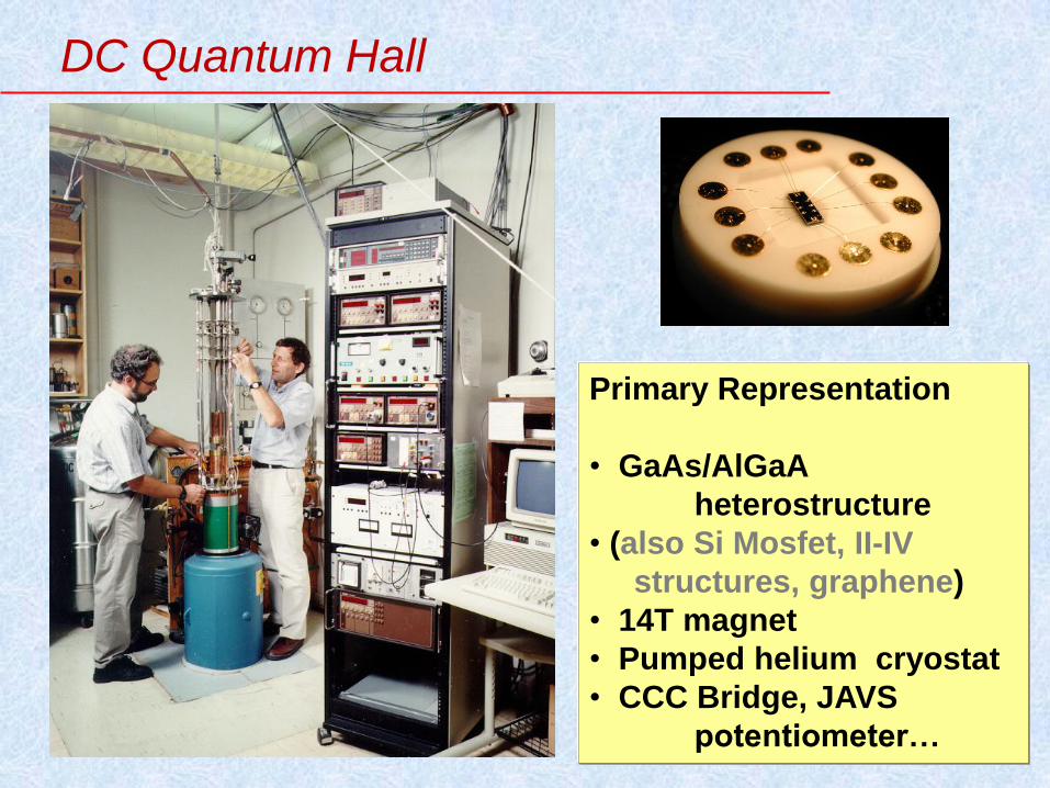
Primary Representation
• GaAs/AlGaA
heterostructure
• (also Si Mosfet, II-IV
structures, graphene)
• 14T magnet
• Pumped helium cryostat
• CCC Bridge, JAVS
potentiometer…
DC Quantum Hall
1 2
3 4
5 6
S
D
RH
Rxx
12906.4035 Ω

CCC Resistance Bridge
In many NMIs the CCC resistance bridge is the primary dc ratio bridge
• for the QHR to resistors
• but scaling 0.1 - 1M
•Noise optimized for step #2 to 100 .
•Bridge leakage effects are exceptionally small.
•Redundant ways to get the same ratio.
Primary resistance ratio bridge measures QHR on steps 2,3,4 & 6.. ratios of 1:1, 10:1, 100:1 and others 0.1 - 100k
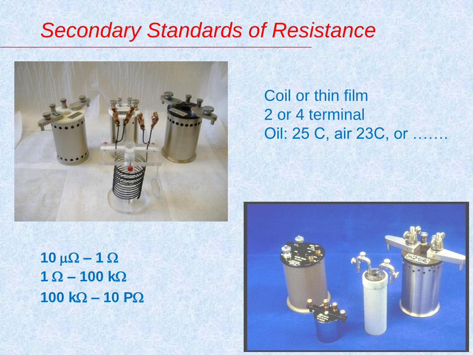
Secondary Standards of Resistance
10 – 1
1 – 100 k
100 k – 10 P
Coil or thin film
2 or 4 terminal
Oil: 25 C, air 23C, or …….
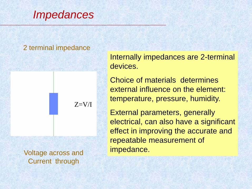
Impedances
Internally impedances are 2-terminal
devices.
Choice of materials determines
external influence on the element:
temperature, pressure, humidity.
External parameters, generally
electrical, can also have a significant
effect in improving the accurate and
repeatable measurement of
impedance.
2 terminal impedance
Z=V/I
Voltage across and
Current through
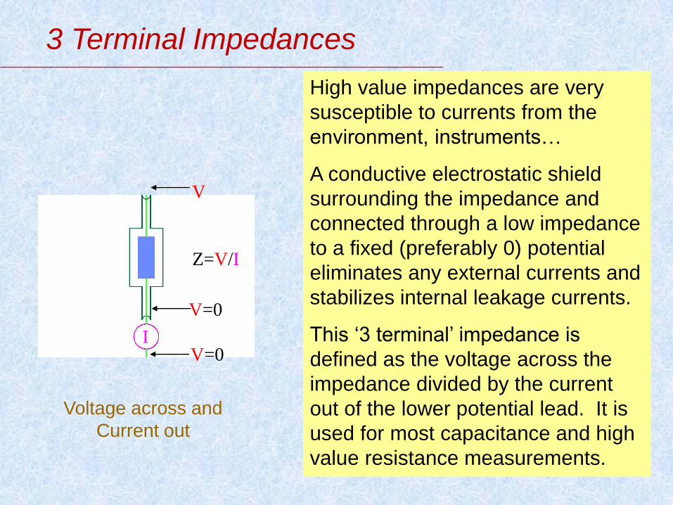
3 Terminal Impedances
High value impedances are very
susceptible to currents from the
environment, instruments…
A conductive electrostatic shield
surrounding the impedance and
connected through a low impedance
to a fixed (preferably 0) potential
eliminates any external currents and
stabilizes internal leakage currents.
This ‘3 terminal’ impedance is
defined as the voltage across the
impedance divided by the current
out of the lower potential lead. It is
used for most capacitance and high
value resistance measurements.
Z=V/I
V
V=0 I
V=0
Voltage across and
Current out

4 Terminal Impedances
Low value impedances suffer from
poorly defined potentials, especially
if current is flowing along the leads
that are measuring the potential.
Measure the potential with leads
that carry no current. Define the
potential junction to the impedance
with low impedances that are
invariant to the current.
This is a ‘4 terminal’ impedance and
is commonly used for resistances
less than 100 kΩ.
4 terminal impedance
Z= (V2-V1)/I
I
V1, i=0
V2, i=0
Voltage across and
Current through
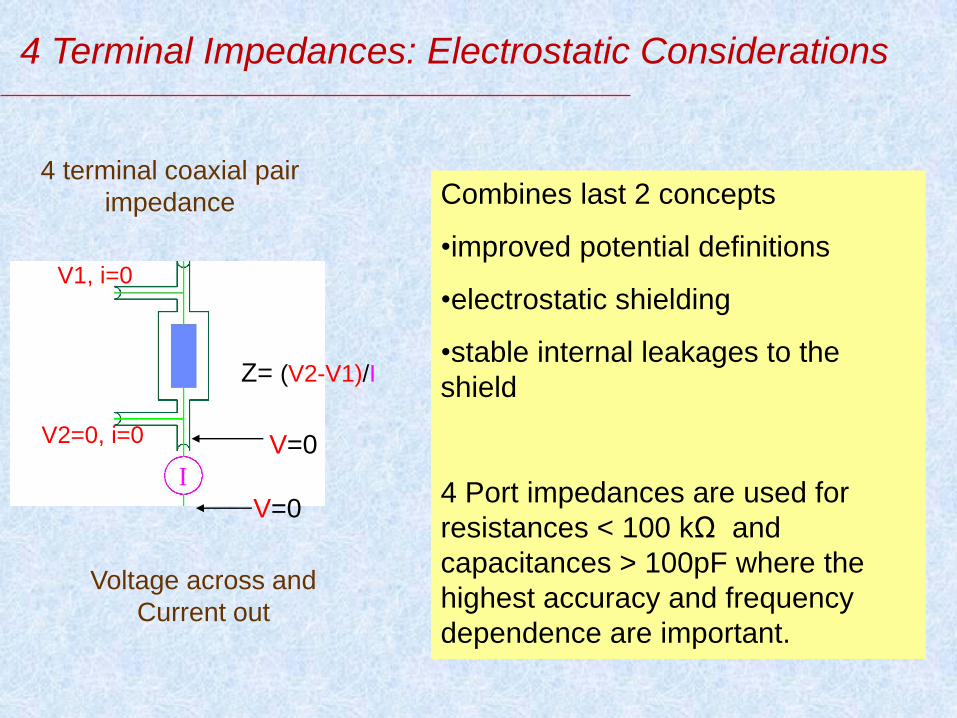
4 Terminal Impedances: Electrostatic Considerations
Combines last 2 concepts
•improved potential definitions
•electrostatic shielding
•stable internal leakages to the
shield
4 Port impedances are used for
resistances < 100 kΩ and
capacitances > 100pF where the
highest accuracy and frequency
dependence are important.
4 terminal coaxial pair
impedance
Voltage across and
Current out
Z= (V2-V1)/I
V1, i=0
V2=0, i=0
V=0
I
V=0

4 Terminal Impedances: Magnetic Considerations
For highest accuracy & frequencies
< 100 kHz, control the magnetic
leakages as well.
•Coaxial cables with equal and
opposite currents in the inner and
outer conductors magnetically
astatic
•Use magnetic shields wherever the
coaxial features are lost.
•Orthogonal current and potential
lead placement magnetically
astatic
4 Terminal Impedance
Voltage across and
Current out
Z= (V2-V1)/I V1, i=0
V2=0, i=0
V=0
I
V=0
Magnetic
Shield
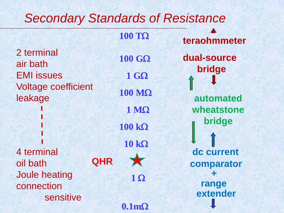
Secondary Standards of Resistance
100 T
100 G
1 G
100 M
1 M
100 k
10 k
1
0.1m
teraohmmeter
dual-source
bridge
automated
wheatstone
bridge
dc current
comparator +
range extender
2 terminal
air bath
EMI issues
Voltage coefficient
leakage
4 terminal
oil bath
Joule heating
connection
sensitive
QHR

Resistance Bridge
Rstd
Rtest
Vs
Vt
detector For precision values,
unknown compared with
known resistor
voltages to 1100V
null detector, grounded
reversing sources nulls
offsets
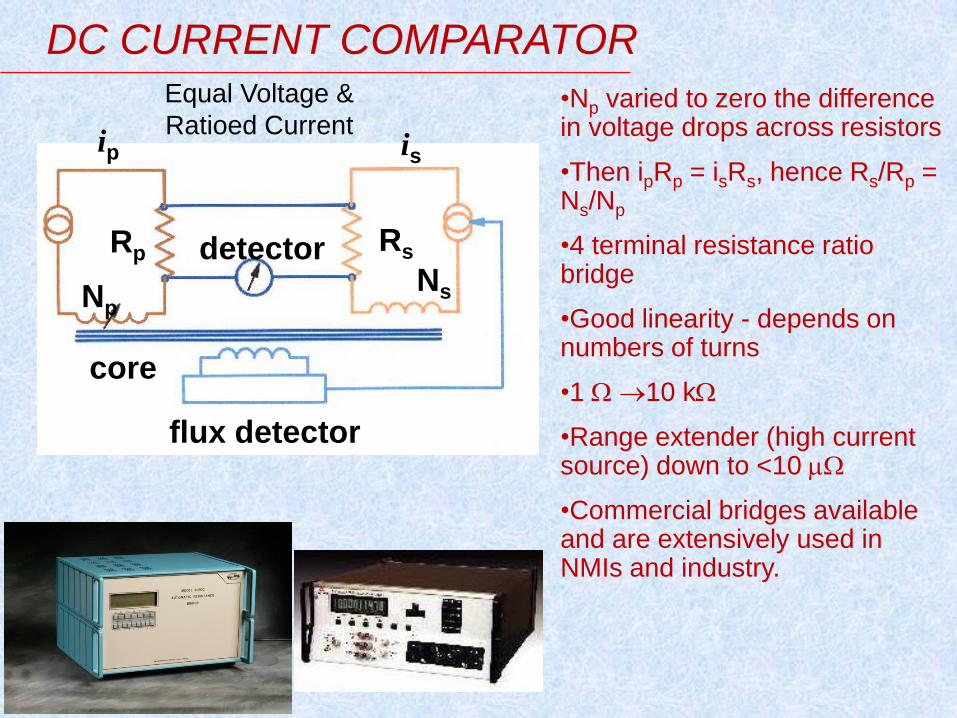
flux detector
core
Np
detector Rs Rp
DC CURRENT COMPARATOR
Ns
ip is
•Np varied to zero the difference in voltage drops across resistors
•Then ipRp = isRs, hence Rs/Rp = Ns/Np
•4 terminal resistance ratio bridge
•Good linearity - depends on numbers of turns
•1 10 k
•Range extender (high current source) down to <10
•Commercial bridges available and are extensively used in NMIs and industry.
Equal Voltage &
Ratioed Current

Hamon Resistor – series & parallel configurations
Chi Vhi Clo Vlo Chi Vhi
Chi Vhi
Series
Total Resistance = nR+R
Parallel
Total Resistance = R+ R n n
Ratio of Series/Parallel = n2
2

Hamon Resistor – Applications
Available from 1 1G
• Voltage Ratios, especially to >1kV
• 10:1 and 100:1 Resistance Ratios
• high resistance as ratio standards
(in the last decade replaced by CCC)
• Power Coefficient determinations
the power per Hamon element resistor, R, is kept constant and with a current independent 10:1 bridge yields the power coefficient.
Fluke 752A
Reference
Divider

Teraohmmeter
100 G 10 P
Rtest =
Vt = 0.1, 1.0 or 10 V
C = 27, 270, 2700 pF
Rtest
Vin Vout
Vt+
Vt-
C
volts compare.
Vin t
CVt
+
-
A timed capacitive charging technique

Temporal shift of resistance
12 May 2008 46 Dave Inglis, NRC Canada

Temporal shift of resistance

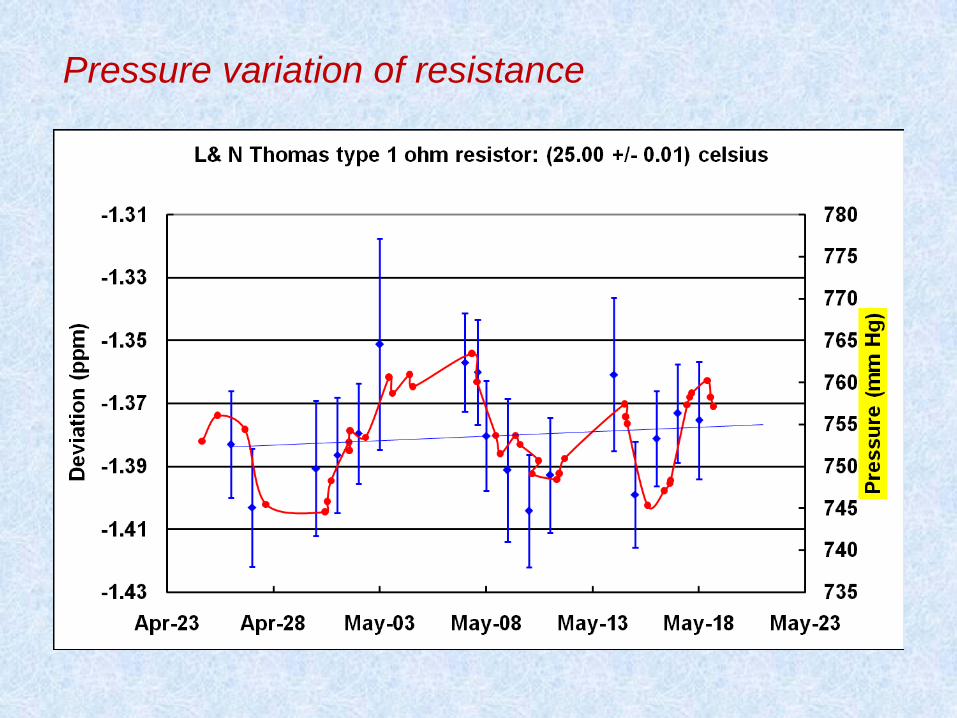
Pressure variation of resistance

Capacitance
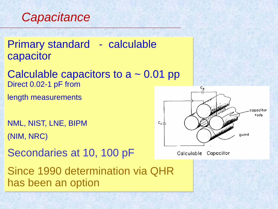
Primary standard - calculable capacitor
Calculable capacitors to a ~ 0.01 pp Direct 0.02-1 pF from
length measurements
NML, NIST, LNE, BIPM
(NIM, NRC)
Secondaries at 10, 100 pF
Since 1990 determination via QHR has been an option
Capacitance
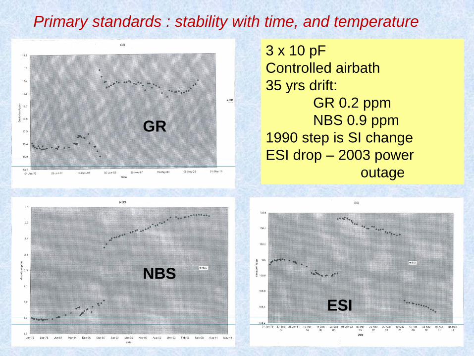
Primary standards : stability with time, and temperature
3 x 10 pF
Controlled airbath
35 yrs drift:
GR 0.2 ppm
NBS 0.9 ppm
1990 step is SI change
ESI drop – 2003 power
outage
GR
NBS
ESI
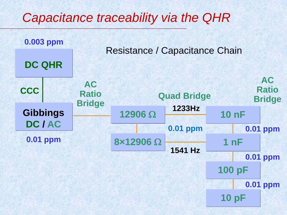
Capacitance traceability via the QHR
10 pF
100 pF
1 nF
10 nF
8×12906
12906 1233Hz
1541 Hz
0.003 ppm
0.01 ppm
0.01 ppm 0.01 ppm
DC QHR
CCC Quad Bridge
Gibbings
DC / AC
AC Ratio
Bridge
0.01 ppm
0.01 ppm
AC Ratio
Bridge
Resistance / Capacitance Chain
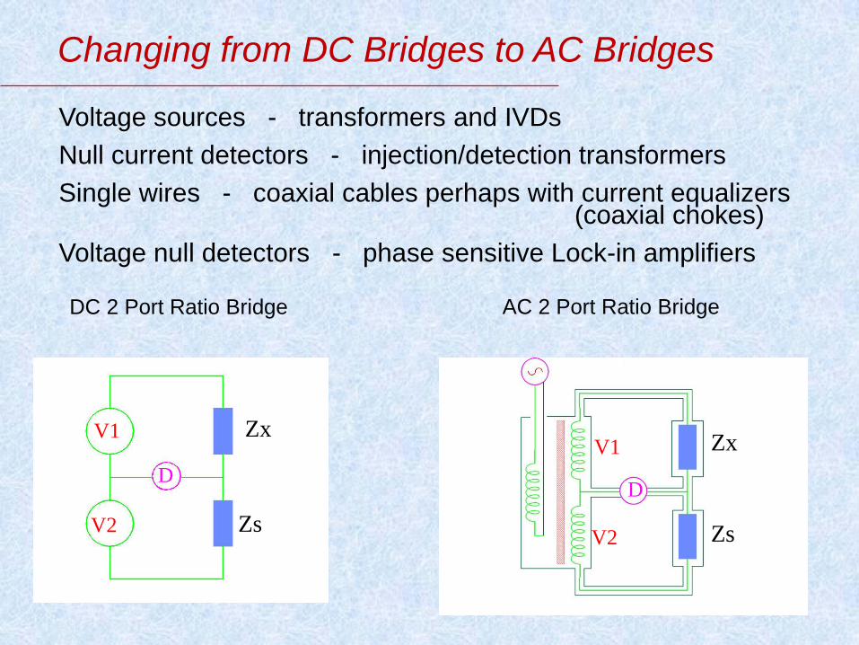
Changing from DC Bridges to AC Bridges
Voltage sources - transformers and IVDs
Null current detectors - injection/detection transformers
Single wires - coaxial cables perhaps with current equalizers (coaxial chokes)
Voltage null detectors - phase sensitive Lock-in amplifiers
V1
V2 Zs
D
Zx V1
V2 Zs
D
Zx
DC 2 Port Ratio Bridge AC 2 Port Ratio Bridge
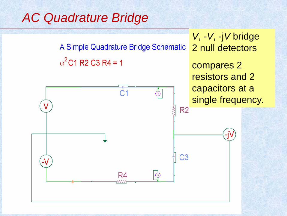
AC Quadrature Bridge
V, -V, -jV bridge
2 null detectors
compares 2
resistors and 2
capacitors at a
single frequency.
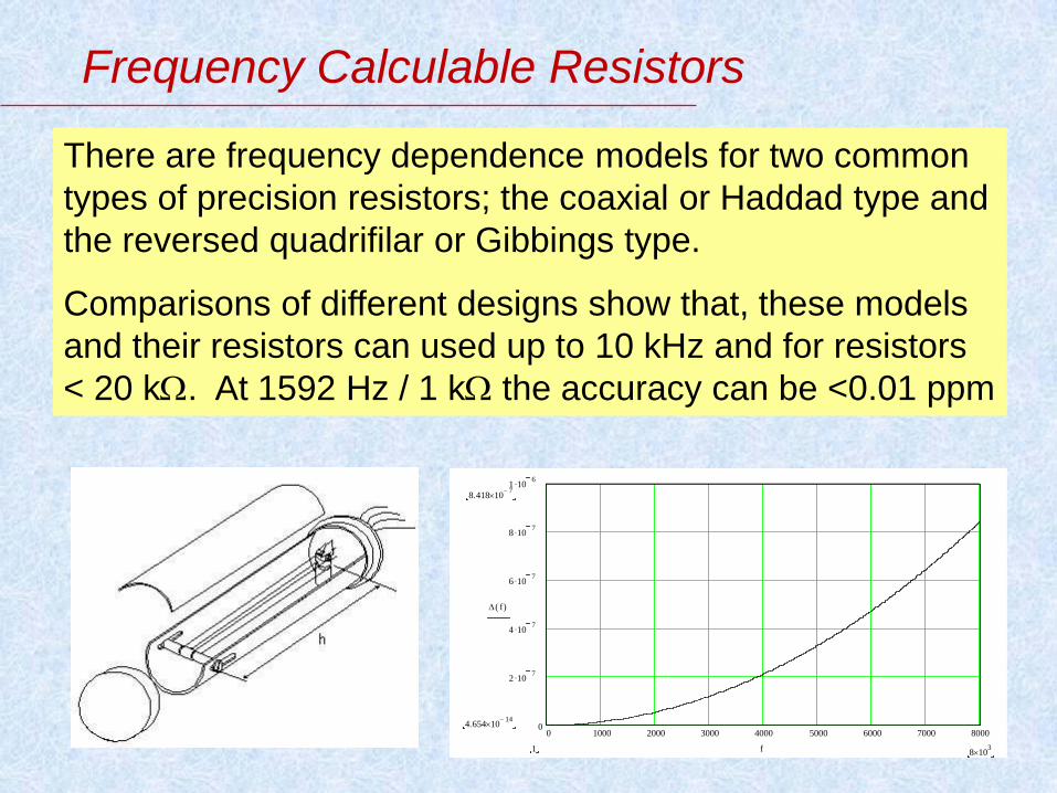
Frequency Calculable Resistors
There are frequency dependence models for two common
types of precision resistors; the coaxial or Haddad type and
the reversed quadrifilar or Gibbings type.
Comparisons of different designs show that, these models
and their resistors can used up to 10 kHz and for resistors
< 20 k. At 1592 Hz / 1 k the accuracy can be <0.01 ppm
0 1000 2000 3000 4000 5000 6000 7000 80000
2 107
4 107
6 107
8 107
1 106
8.418 107
4.654 1014
f( )
8 103
1 f
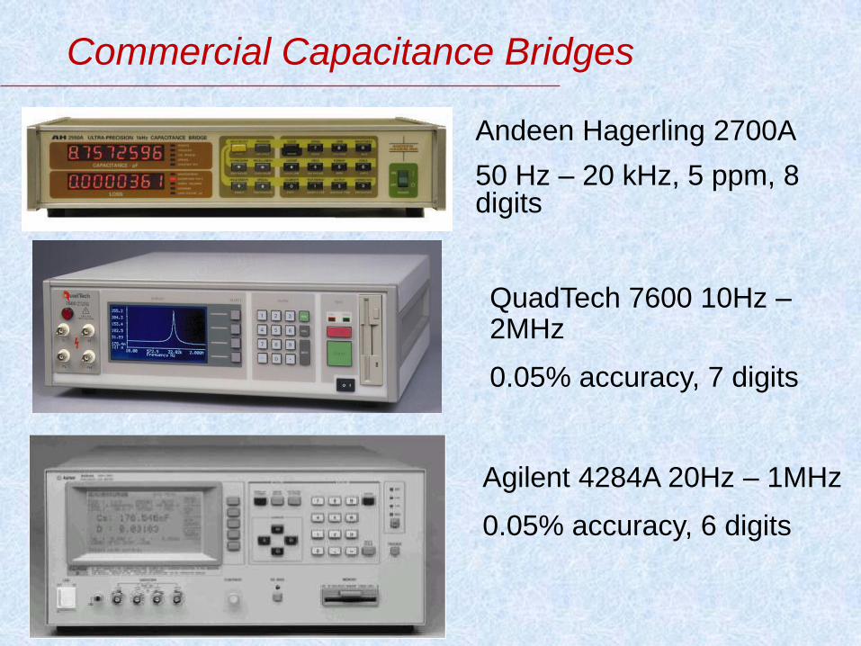
Commercial Capacitance Bridges
Agilent 4284A 20Hz – 1MHz
0.05% accuracy, 6 digits
Andeen Hagerling 2700A
50 Hz – 20 kHz, 5 ppm, 8 digits
QuadTech 7600 10Hz – 2MHz
0.05% accuracy, 7 digits
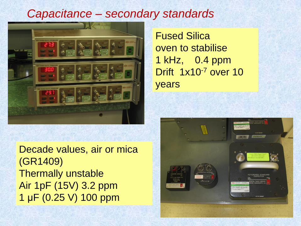
Capacitance – secondary standards
Decade values, air or mica
(GR1409)
Thermally unstable
Air 1pF (15V) 3.2 ppm
1 μF (0.25 V) 100 ppm
Fused Silica
oven to stabilise
1 kHz,
0.4 ppm
Drift 1x10⁻⁷ over 10
years

Capacitor stabilisation
Inductance

100 uH (ohms)
→ 10 H (kohms)
Measure resistance
(HP3458A) – use with
temperature dependance
Use LCR meter as transfer
standard
Gives 100 ppm at 1 mHm
500 ppm at 10 H
Link to SI using Maxwell-Wien bridge; with
traceable capacitors and resistors
Calibrate clients with commercial LCR meter
Calibration of inductors
Picture of
inductors
1 mH 2 mH
50 µH
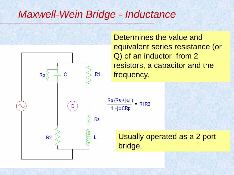
Maxwell-Wein Bridge - Inductance
Determines the value and
equivalent series resistance (or
Q) of an inductor from 2
resistors, a capacitor and the
frequency.
Usually operated as a 2 port
bridge.

ac/dc transfer
AC/DC Transfer
The equivalence of DC and AC quantities is
achieved when they produce the same electrical
power which in turn must be equivalent to
mechanical power. Thus temperature is a good
and unambiguous indicator of this equivalence.
ac JAVS are being developed : limited range of
voltage and frequency to date. Very few in
operation yet.
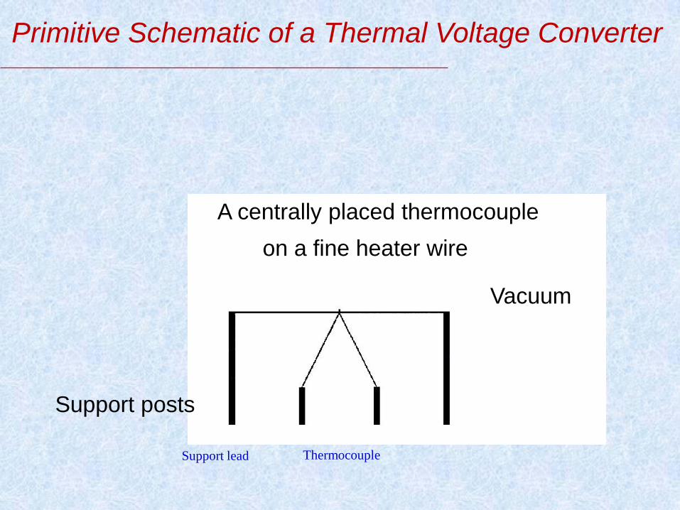
Primitive Schematic of a Thermal Voltage Converter
Support lead Thermocouple
Vacuum
A centrally placed thermocouple
Support posts
on a fine heater wire

UHF-pattern single junction thermal converter (SJTC)
Evacuated glass
envelope
Feed-through
Feed-through thermocouple leads
Thermocouple Heater
Insulating bead
20 mm

ac-dc voltage transfer difference
dcac
dcdcRdcN
VV
VVV
ac
dcRdcNdc E
EEE
2
where Vac is the rms value of the ac input voltage, Vdc is the dc input voltage, which when reversed produces the same mean output voltage of the transfer standard as Vac. EdcN, EdcR and Eac are the output voltages of the standard when the appropriate voltages have been applied.
The ac-dc voltage transfer difference δ of a transfer standard
is defined as:
dcEacE
dc
dcac
V
VV

PTB 3-dimensional MJTC
http://www.ptb.de/en/org/2/21/212/mjtc.htm
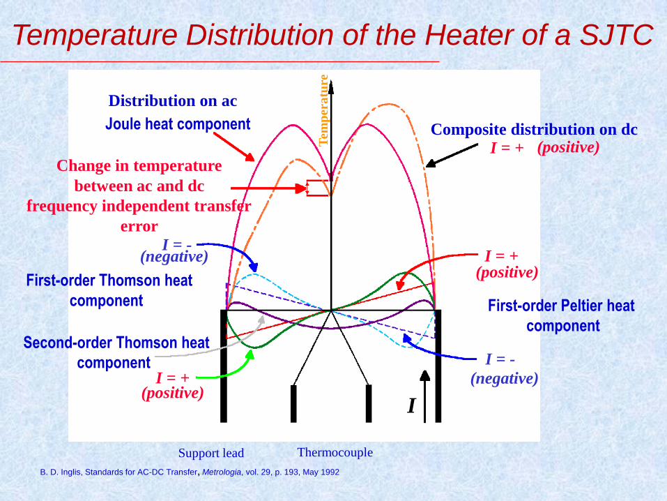
Temperature Distribution of the Heater of a SJTC
B. D. Inglis, Standards for AC-DC Transfer , Metrologia , vol. 29, p. 193, May 1992
Distribution on ac
Joule heat component
Change in temperature
between ac and dc
frequency independent transfer
error
I = -
I = -
I = +
I = + (positive)
(positive)
(negative)
(negative)
First-order Thomson heat
component
Second-order Thomson heat
component
First-order Peltier heat
component
Composite distribution on dc I = + (positive)
I
Support lead Thermocouple
Tem
per
atu
re

Shunt TVC - V2S1f 5 mA/1.1V/220 Ohm
AC-DC Voltage Transfer Difference
2 SJTC 90 Ohm/5 mA + approx. 40 Ohm series resistor
Frequency/kHz
10 100 1000 10000 100000
AC
-DC
Vo
lta
ge T
ran
sfe
r D
iffe
ren
ce
V
V
/V
-5
0
5
10
15
20
25
E = 14 mV (4.9 mA)
E = 11 mV (4.2 mA)
E = 9 mV (3.8 mA)
E = 6 mV ( 3.1 mA)
E = 2 mV (1.8 mA)
Thermoelectric ac-dc difference
Stray L, C Thermal ripple
Input current level change
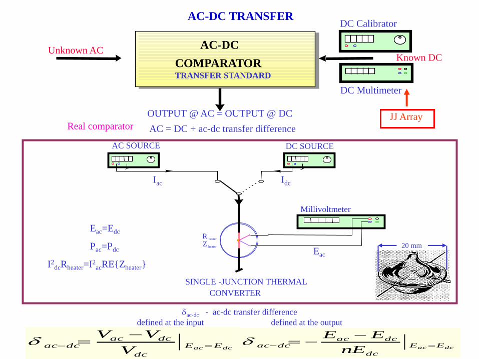
AC-DC
COMPARATOR TRANSFER STANDARD
AC-DC TRANSFER
Unknown AC Known DC
DC Calibrator
DC Multimeter
OUTPUT @ AC = OUTPUT @ DC
AC = DC + ac-dc transfer difference Real comparator JJ Array
Millivoltmeter
AC SOURCE DC SOURCE
R heater
Z heater
SINGLE -JUNCTION THERMAL
CONVERTER
Eac=Edc
Pac=Pdc
I2dcRheater=I2
acRE{Zheater}
Iac Idc
Eac
dcac EE
dc
dcacdcac
V
VV
dcac EE
dc
dcacdcac
nE
EE
ac-dc - ac-dc transfer difference
defined at the input defined at the output
20 mm
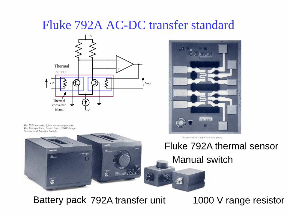
Fluke 792A AC-DC transfer standard
Fluke 792A thermal sensor
Battery pack 792A transfer unit 1000 V range resistor
Manual switch
-V
Vin Vout
-
+ Thermal
sensor
Thermal
converter
island
+V

Comparison of Low Voltage Transfer Standards
IMTC98-S20

Questions??
Feel free to contact me at
Or, since I have left NRC and the
above mail won’t work forever, at