Electrical maintenance fundamentals
34
1 Electrical Maintenance Fundamentals Note: presentation best viewed as Notes Page
-
Upload
james-shearer -
Category
Devices & Hardware
-
view
408 -
download
5
Transcript of Electrical maintenance fundamentals
1
Electrical Maintenance Fundamentals
Note: presentation best viewed as Notes Page
2
Objectives Define the unit of electricity and current
flow Define the three electrical qualities
present in electrical circuits. State and apply Ohm’s Law Measurement basics
3
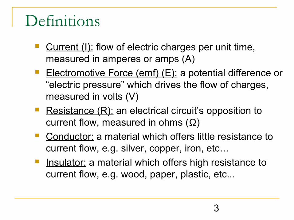
Definitions Current (I): flow of electric charges per unit time,
measured in amperes or amps (A) Electromotive Force (emf) (E): a potential difference or
“electric pressure” which drives the flow of charges, measured in volts (V)
Resistance (R): an electrical circuit’s opposition to current flow, measured in ohms (Ω)
Conductor: a material which offers little resistance to current flow, e.g. silver, copper, iron, etc…
Insulator: a material which offers high resistance to current flow, e.g. wood, paper, plastic, etc...

4
Types of Electricity Static Electricity - no motion of free
charges
Current Electricity - motion of free charges Direct Current (DC) Alternating Current (AC)
5
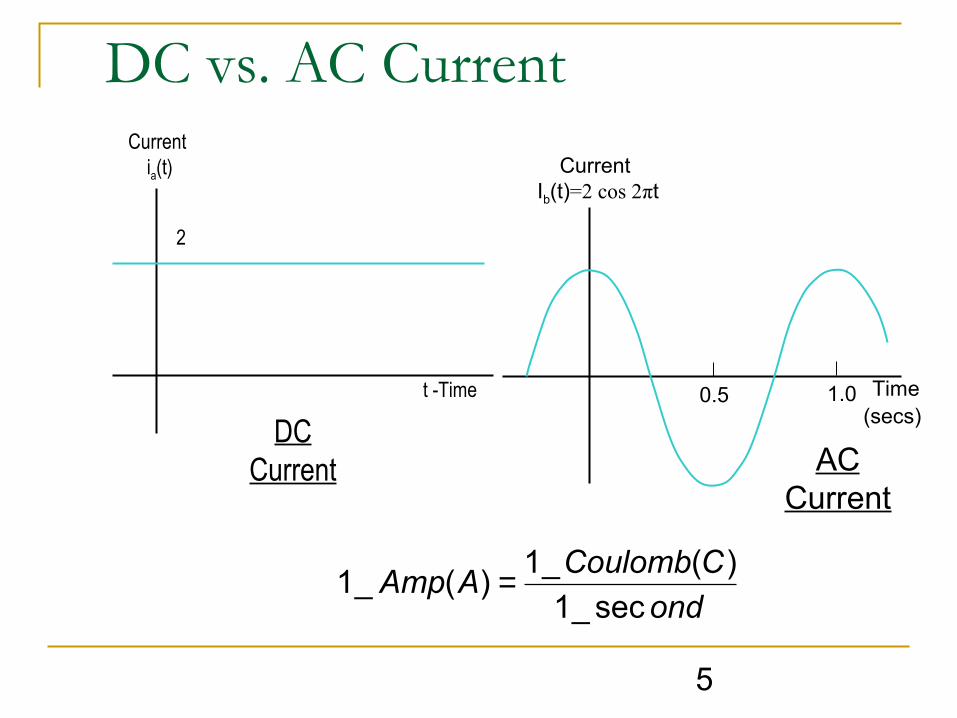
t -Time
DC Current
Current ia(t)
2
Current Ib(t)=2 cos 2πt
0.5 1.0
AC Current
Time (secs)
ond
CCoulombAAmp
sec_1
)(_1)(_1 =
DC vs. AC Current
6
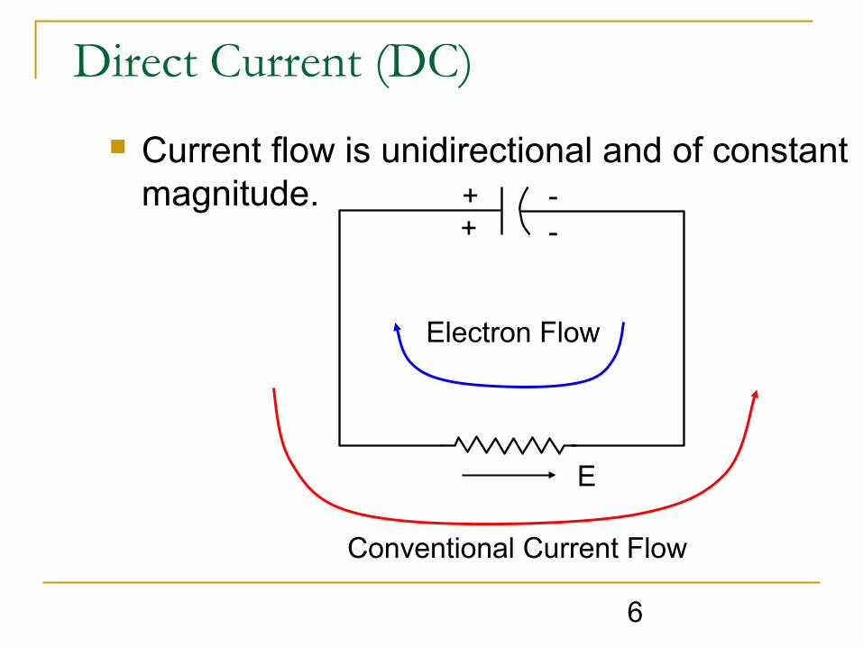
Direct Current (DC)
Current flow is unidirectional and of constant magnitude.
Conventional Current Flow
Electron Flow
+ --+
E

7
Alternating Current (AC)
Current is constantly changing in magnitude and direction at regular intervals.
Current is a function of time and usually varies as a sine function.
I
t
8
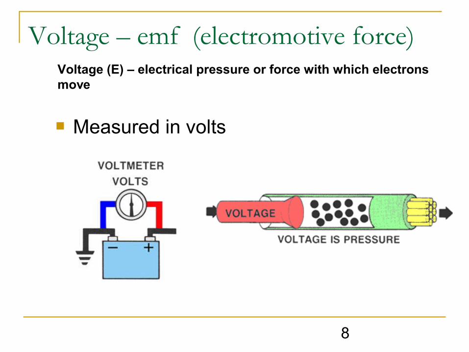
Voltage – emf (electromotive force)Voltage (E) – electrical pressure or force with which electrons move
Measured in volts

9
Electromotive force - Emf
Water Pump
Shutoff Valve
High Pressure
Low Pressure
Switch
BatteryR -
resistor
Low Potential
High Potential
E

10
Resistance/Impedance Resistance / Impedance (R / Z or Ω) - opposition that an element or material has to the flow of electrons
Ohm’s Law states that one volt (E) will push one amp of current (I) through one ohm (Ω) of resistance (R).
Resistance (DC circuit); Impedance (AC circuit) Ohm’s Law formula: E=IR
11
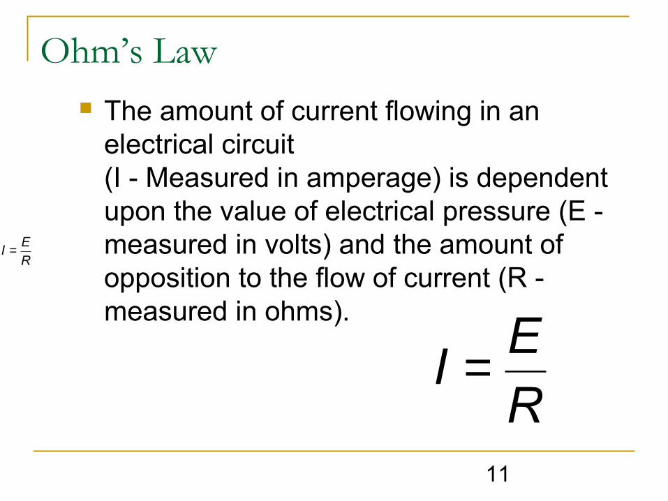
Ohm’s Law The amount of current flowing in an
electrical circuit(I - Measured in amperage) is dependent upon the value of electrical pressure (E - measured in volts) and the amount of opposition to the flow of current (R - measured in ohms).
R
EI =
R
EI =
12
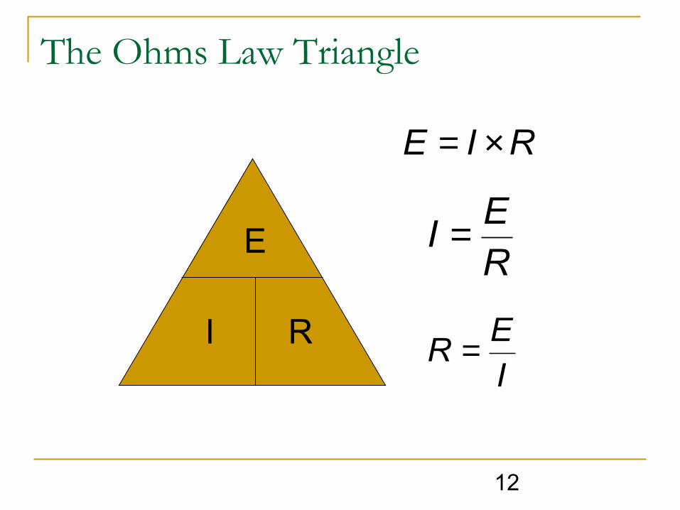
The Ohms Law Triangle
RIE ×=
R
EI =
I
ER =
E
I RI
ER =
13
Ohm’s Law
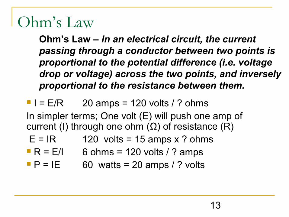
I = E/R 20 amps = 120 volts / ? ohmsIn simpler terms; One volt (E) will push one amp of current (I) through one ohm (Ω) of resistance (R) E = IR 120 volts = 15 amps x ? ohms R = E/I 6 ohms = 120 volts / ? amps P = IE 60 watts = 20 amps / ? volts
Ohm’s Law – In an electrical circuit, the current passing through a conductor between two points is proportional to the potential difference (i.e. voltage drop or voltage) across the two points, and inversely proportional to the resistance between them.
14
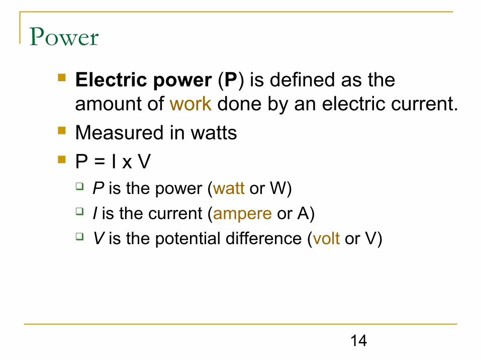
Power Electric power (P) is defined as the
amount of work done by an electric current. Measured in watts P = I x V
P is the power (watt or W) I is the current (ampere or A) V is the potential difference (volt or V)
15
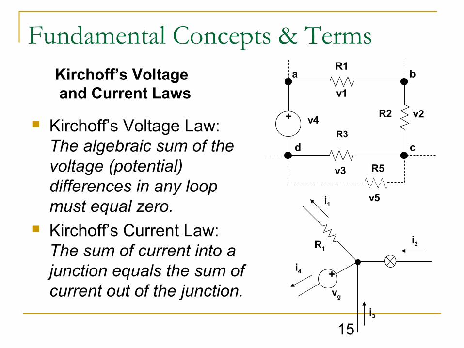
Fundamental Concepts & Terms Kirchoff’s Voltage and Current Laws
Kirchoff’s Voltage Law:The algebraic sum of the voltage (potential) differences in any loop must equal zero.
Kirchoff’s Current Law:The sum of current into a junction equals the sum of current out of the junction.
R1
R2
R3
R5
v2
v1
v4
v5
v3
a b
d c
+
+
vg
i3
i4
i1
R1i2
16
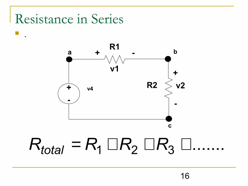
Resistance in Series .
R1
R2 v2
v1
v4
-a b
c
+
+
+
--
.......321 +++= RRRRtotal
17
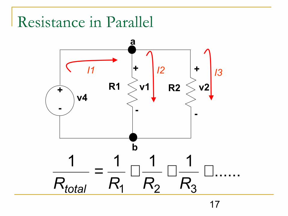
Resistance in Parallel
R1 R2 v2v1v4
-
b
+
+ +
--
a
I1 I2 I3
......1111
321
+++=RRRRtotal

18
Measuring Electrical Performance First and Foremost - follow proper safety
rules Common Electrical instruments
Voltmeters Ammeters Ohmmeters Megohmmeters Wattmeters
19
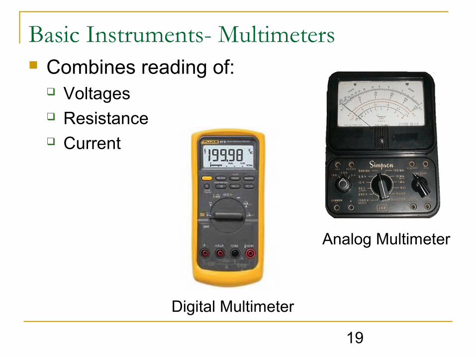
Basic Instruments- Multimeters Combines reading of:
Voltages Resistance Current
Digital Multimeter
Analog Multimeter

20
Digital Multimeters
Measurement Device Circuit Symbol
Voltage Voltmeter
Current Ammeter
Resistance Ohmmeter
V
A
Ω
“Through”
“Across”
“Across”(and Not in circuit)

21
GALVANOMETER
PointerN
S
Moving coil
Coiled spring

22
Measuring Voltage
+
Battery
-
V
V
A COM
12.000
A
OFFA
23
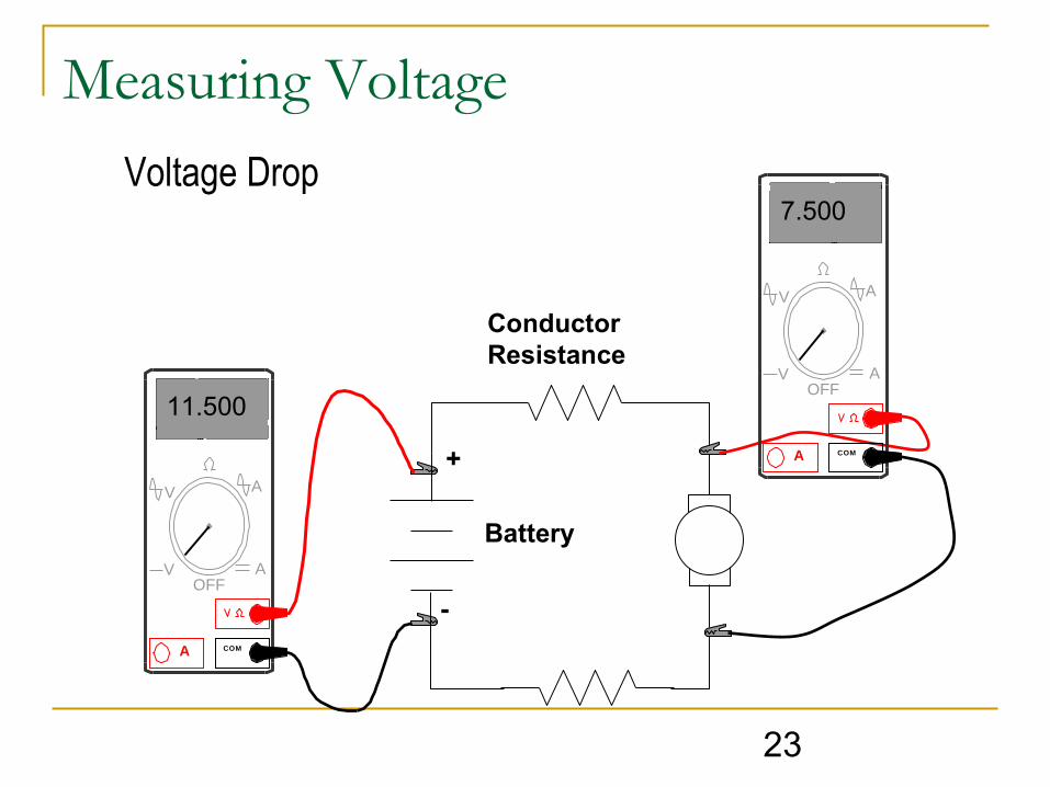
Measuring Voltage
+
Battery
-
Conductor Resistance
V
V
A COM
11.500
A
OFFA
V
V
A COM
7.500
A
OFFA
Voltage Drop

24
Measuring Current
+
Battery
-
A
V
A COM
.5000
V
AOFF
Break circuit to connect meter. Note: meter leads are moved to different inputs for current testing.

25
Measuring Current Cont’d
Never clamp two wires at once!
26
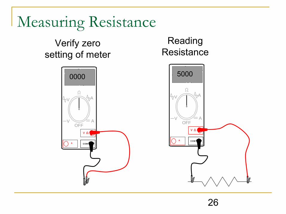
Measuring Resistance
A
V
A COM
5000
V
AOFF
A
V
A COM
0000
V
AOFF
Verify zero setting of meter
Reading Resistance

27
Megohmmeter (Megger)

28
Megger Testing
GL E

29
Proof Testing & Procedure
Metal conduit
Insulation

30
Testing Generators/Motors When testing
generators, motors, or transformers each winding/phase should be tested in sequence and separately while all the other windings are grounded. Testing this way, the insulation between phases is also tested.

31
Power Electrical power is defined as the rate at
which electrical energy is supplied to a circuit or consumed by a load.
The watt (w) is the unit of power
IEtime
workP ×==
Where E = volts and I = current
PI E
32
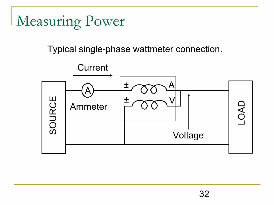
Measuring Power
Typical single-phase wattmeter connection.S
OU
RC
E
A
LOA
D
A
V
Voltage
Current
Ammeter
±
±

33
TH
RE
E P
HA
SE
SO
UR
CE
TH
RE
E P
HA
SE
LO
ADA
V
±±
A
V
±
±
Measuring Power
Measuring Power Cont’d
Typical single-phase wattmeter connection.
34
Summary
Review Objectives Question and Answer Session